CUSTOMIZE PARAMETERS
PROCEDURE
1. CUSTOMIZE SFI SYSTEM (for 2GR-FKS)
Click here

2. CUSTOMIZE HYBRID CONTROL SYSTEM
Click here
3. CUSTOMIZE LANE DEPARTURE ALERT SYSTEM (w/ Steering Control) (for HV Model)
Click here
4. CUSTOMIZE LANE DEPARTURE ALERT SYSTEM (w/ Steering Control) (for Gasoline Model)
Click here
5. CUSTOMIZE ADAPTIVE VARIABLE SUSPENSION SYSTEM
Click here
6. CUSTOMIZE POWER STEERING SYSTEM (for Gasoline Model)
Click here
7. CUSTOMIZE POWER TILT AND POWER TELESCOPIC STEERING COLUMN SYSTEM (for HV Model)
Click here
8. CUSTOMIZE POWER TILT AND POWER TELESCOPIC STEERING COLUMN SYSTEM (for Gasoline Model)
Click here
9. CUSTOMIZE INTELLIGENT CLEARANCE SONAR SYSTEM (for HV Model)
Click here
10. CUSTOMIZE INTELLIGENT CLEARANCE SONAR SYSTEM (for Gasoline Model)
Click here
11. CUSTOMIZE INTUITIVE PARKING ASSIST SYSTEM (for HV Model)
Click here
12. CUSTOMIZE INTUITIVE PARKING ASSIST SYSTEM (for Gasoline Model)
Click here
13. CUSTOMIZE BLIND SPOT MONITOR SYSTEM (for HV Model)
Click here
14. CUSTOMIZE BLIND SPOT MONITOR SYSTEM (for Gasoline Model)
Click here
15. CUSTOMIZE POWER DOOR LOCK CONTROL SYSTEM (for HV Model)
Click here
16. CUSTOMIZE POWER DOOR LOCK CONTROL SYSTEM (for Gasoline Model)
Click here
17. CUSTOMIZE WIRELESS DOOR LOCK CONTROL SYSTEM (for HV Model)
Click here
18. CUSTOMIZE WIRELESS DOOR LOCK CONTROL SYSTEM (for Gasoline Model)
Click here
19. CUSTOMIZE SMART KEY SYSTEM (for Entry Function, HV Model)
Click here
20. CUSTOMIZE SMART KEY SYSTEM (for Entry Function, Gasoline Model)
Click here
21. CUSTOMIZE SMART KEY SYSTEM (for Start Function, HV Model)
Click here
22. CUSTOMIZE SMART KEY SYSTEM (for Start Function, Gasoline Model)
Click here
23. CUSTOMIZE THEFT DETERRENT SYSTEM (for HV Model)
Click here
24. CUSTOMIZE THEFT DETERRENT SYSTEM (for Gasoline Model)
Click here
25. CUSTOMIZE LIGHTING SYSTEM (INT) (for HV Model)
Click here
26. CUSTOMIZE LIGHTING SYSTEM (INT) (for Gasoline Model)
Click here
27. CUSTOMIZE METER / GAUGE SYSTEM (for HV Model)
Click here
28. CUSTOMIZE METER / GAUGE SYSTEM (for Gasoline Model)
Click here
29. CUSTOMIZE HEADUP DISPLAY SYSTEM (for HV Model)
Click here
30. CUSTOMIZE HEADUP DISPLAY SYSTEM (for Gasoline Model)
Click here
31. CUSTOMIZE PRE-COLLISION SYSTEM (for HV Model)
Click here
32. CUSTOMIZE PRE-COLLISION SYSTEM (for Gasoline Model)
Click here
33. CUSTOMIZE FRONT POWER SEAT CONTROL SYSTEM (for HV Model with Memory)
Click here
34. CUSTOMIZE FRONT POWER SEAT CONTROL SYSTEM (for Gasoline Model with Memory)
Click here
35. CUSTOMIZE SEAT BELT WARNING SYSTEM (for HV Model)
Click here
36. CUSTOMIZE SEAT BELT WARNING SYSTEM (for Gasoline Model)
Click here
37. CUSTOMIZE AIR CONDITIONING SYSTEM (for HV Model)
Click here
38. CUSTOMIZE AIR CONDITIONING SYSTEM (for Gasoline Model)
Click here
39. CUSTOMIZE POWER WINDOW CONTROL SYSTEM (for HV Model)
Click here
40. CUSTOMIZE POWER WINDOW CONTROL SYSTEM (for Gasoline Model)
Click here
41. CUSTOMIZE SLIDING ROOF SYSTEM (for HV Model)
Click here
42. CUSTOMIZE SLIDING ROOF SYSTEM (for Gasoline Model)
Click here
43. CUSTOMIZE LUGGAGE COMPARTMENT DOOR OPENER SYSTEM (for HV Model)
Click here
44. CUSTOMIZE LUGGAGE COMPARTMENT DOOR OPENER SYSTEM (for Gasoline Model)
Click here
45. CUSTOMIZE POWER MIRROR CONTROL SYSTEM (for HV Model with Memory)
Click here
46. CUSTOMIZE POWER MIRROR CONTROL SYSTEM (for Gasoline Model with Memory)
Click here
47. CUSTOMIZE LIGHTING SYSTEM (EXT) (for HV Model with Cornering Light)
Click here
48. CUSTOMIZE LIGHTING SYSTEM (EXT) (for Gasoline Model with Cornering Light)
Click here
49. CUSTOMIZE LIGHTING SYSTEM (EXT) (for HV Model without Cornering Light)
Click here
50. CUSTOMIZE LIGHTING SYSTEM (EXT) (for Gasoline Model without Cornering Light)
Click here
51. CUSTOMIZE VEHICLE PROXIMITY NOTIFICATION SYSTEM
Click here
INITIALIZATION
PROCEDURES NECESSARY WHEN CABLE IS DISCONNECTED/RECONNECTED TO NEGATIVE (-) AUXILIARY BATTERY TERMINAL (for HV Model)
|
Necessary Procedures | Effect/Inoperative Function When Necessary Procedures are not Performed |
Link |
|---|---|---|
|
Perform steering sensor zero point calibration |
Lane Departure Alert System (w/ Steering Control) |
|
|
Pre-collision System | ||
|
Intelligent Clearance Sonar System* | ||
|
Lighting System (for HV Model with Cornering Light) | ||
|
Memorize steering angle neutral point |
Parking Assist Monitor System |
|
|
Panoramic View Monitor System |
|
*: When performing learning using the Techstream.
Click here

NOTICE:
|
Necessary Procedures | Effect/Inoperative Function When Necessary Procedures are not Performed |
Link |
|---|---|---|
| Perform steering sensor zero point calibration |
Lane Departure Alert System (w/ Steering Control) |
|
|
Pre-collision System | ||
|
Intelligent Clearance Sonar System* | ||
|
Lighting System (for Gasoline Model with Cornering Light) | ||
|
Memorize steering angle neutral point |
Parking Assist Monitor System |
|
|
Panoramic View Monitor System |
|
PROCEDURES NECESSARY WHEN CABLE IS DISCONNECTED/RECONNECTED TO NEGATIVE (-) AUXILIARY BATTERY TERMINAL (for Gasoline Model)
*: When performing learning using the Techstream.
Click here
NOTICE:
PROCEDURES NECESSARY WHEN ECU OR OTHER PARTS ARE REPLACED (for HV Model)
|
Replaced Part or Performed Procedure |
Necessary Procedure | Effect/Inoperative Function when Necessary Procedures are not Performed |
Link |
|---|---|---|---|
| ECM |
Perform Vehicle Identification Number (VIN) registration |
MIL illuminates |
|
| Inspection after repair |
|
|
|
Inverter with converter assembly |
Resolver learning |
|
|
|
Hybrid vehicle transaxle assembly |
| ||
| HV battery |
Battery status info update |
HV battery status information cannot be updated |
|
|
Hybrid battery terminal block |
High voltage fuse accumulated load history reset |
DTCs are stored | |
| Millimeter wave radar sensor assembly |
Adjust millimeter wave radar sensor assembly |
|
|
| Adjust forward recognition camera |
|
|
|
|
|
|
|
|
|
|
|
| ||
|
| ||
| Parking Brake ECU (brake actuator assembly) |
Operate the electric parking brake switch (electric parking brake switch assembly) |
Parking brake indicator light blinks when the power switch is first turned on (IG) |
|
|
Rack and pinion power steering gear assembly |
|
|
|
|
DCM (telematics transceiver) | DCM activation |
Safety Connect System |
|
|
Back-up battery | Perform the reset back-up battery condition |
| |
|
Steering sensor | Steering angle zero point learning (Initialize intelligent clearance sonar system) |
|
|
|
| ||
| Clearance warning ECU assembly |
| ||
| Steering sensor |
| Parking Assist Monitor System |
|
|
Suspension, tires, etc.*1 | Rear television camera assembly optical axis adjustment (Back camera position setting) | ||
|
Television camera assembly |
| ||
| Steering sensor |
Steering angle zero point learning (Initialize panoramic view monitor system) |
Panoramic View Monitor System |
|
|
Parking assist ECU |
| ||
| Television camera assembly |
| ||
| Front television camera view adjustment | ||
| Side television camera view adjustment | ||
|
| ||
| Suspension, tires, etc.*1 |
| ||
| Blind spot monitor sensor |
Blind spot monitor beam axis adjustment |
|
|
|
Inner rear view mirror assembly*3 | Register codes in the garage door opener system |
Garage Door Opener System |
|
| Code registration (Smart key System (for Start Function)) |
|
|
| Zero point calibration (Occupant classification system) |
|
|
| Initialize position control ECU |
Front Power Seat Control System |
|
| Servo motor initialization (Air conditioning system) |
DTCs are stored |
|
| Initialize power window control system |
|
|
| Initialize sliding roof system |
|
|
| Synchronize the vehicle information |
Lighting system (for HV Model with Cornering Light) |
|
| Change grille shutter control mode and/or perform initialization |
Grille Shutter System |
|
*1: If the vehicle height has changed due to suspension or tire replacement.
*2: Only necessary when Television camera assembly has been removed/installed or replaced.
*3: w/ Garage Door Opener System
PROCEDURES NECESSARY WHEN ECU OR OTHER PARTS ARE REPLACED (for Gasoline Model)
|
Replaced Part or Performed Procedure |
Necessary Procedure | Effect/Inoperative Function when Necessary Procedures are not Performed |
Link |
|---|---|---|---|
|
ECM | Vehicle Identification Number (VIN) registration |
MIL comes on |
|
|
ECU communication ID registration (Immobiliser system) |
Engine start function |
| |
| Inspection after repair |
|
|
|
Millimeter wave radar sensor assembly |
Adjust millimeter wave radar sensor assembly |
|
|
| Adjust forward recognition camera |
|
|
|
Automatic transaxle assembly |
|
|
|
|
| ||
| ECM (If transaxle compensation code read from ECM) |
| ||
| ECM (If transaxle compensation code not read from ECM) |
| ||
| Automatic transaxle fluid |
ATF thermal degradation estimate reset |
The value of the Data List item "ATF Thermal Degradation Estimate" is not estimated correctly |
|
|
Absorber control ECU | Registration of vehicle identification information |
|
|
|
|
|
|
| Perform system variant learning and acceleration sensor zero point calibration |
|
|
|
Skid control ECU (brake actuator assembly) |
Operate the electric parking brake switch (electric parking brake switch assembly) |
Parking brake indicator light blinks when the engine switch is first turned on (IG) |
|
|
Rack and pinion power steering gear assembly |
|
|
|
|
DCM (telematics transceiver) |
DCM activation |
Safety Connect System |
|
|
Back-up battery | Perform the reset back-up battery condition |
| |
|
Steering sensor | Steering angle zero point learning (Initialize intelligent clearance sonar system) |
|
|
|
| ||
| Clearance warning ECU assembly |
| ||
| Steering sensor |
| Parking Assist Monitor System |
|
|
Suspension, tires, etc.*2 |
Rear television camera assembly optical axis adjustment (Back camera position setting) | ||
|
Television camera assembly |
| ||
| Steering sensor |
Steering angle zero point learning (Initialize panoramic view monitor system) |
Panoramic View Monitor System |
|
|
Parking assist ECU |
| ||
| Television camera assembly |
| ||
| Front television camera view adjustment | ||
| Side television camera view adjustment | ||
|
| ||
| Suspension, tires, etc.*2 |
| ||
| Blind spot monitor sensor |
Blind spot monitor beam axis adjustment |
|
|
| Register codes in the garage door opener system |
Garage Door Opener System |
|
| Code registration (Smart Key System (for Start Function)) |
|
|
| Zero point calibration (Occupant Classification System) |
|
|
| Initialize position control ECU |
Front Power Seat Control System |
|
| Servo motor initialization (Air conditioning system (for Automatic Air Conditioning System)) |
DTCs are output |
|
| Initialize power window control system |
|
|
| Initialize sliding roof system |
|
|
| Synchronize the vehicle information |
Lighting system (for Gasoline Model with Cornering Light) |
|
INSPECTION MODE PROCEDURE
INSPECTION MODE (for HV Model)
NOTICE:
When operating the vehicle in an inspection mode for an operation such as a speedometer test, a DTC may be stored. Therefore, if the warning light illuminates, check for DTCs using the Techstream and clear the DTCs.
HINT:
If the engine is warmed up and the HV battery is charged, the engine will stop after the vehicle is stopped. If the engine is required to run continuously even after the vehicle is stopped, such as for an ignition timing check, switch to maintenance mode.
(a) The following table shows the types of inspection mode that are available, their purpose and the control that occurs in each mode.
|
Mode (Display) | Purpose |
Control |
|---|---|---|
| 2WD MAINTENANCE MODE (2WD for measuring Exhaust Gas) |
|
|
| 2WD CERTIFICATION MODE (2WD for cutting TR(A)C) |
For performing tests using a speedometer tester, two-wheel chassis dynamometer, etc. |
Cancels traction control |
|
4WD MAINTENANCE MODE (4WD for measuring Exhaust Gas) |
|
|
| 4WD CERTIFICATION MODE (4WD for cutting TR(A)C) |
For performing tests using a speedometer tester, four-wheel chassis dynamometer, etc. |
Cancels traction control |
(b) Vehicle conditions
(1) Before activating inspection mode, turn the air conditioning off, start the hybrid system with the shift lever in P or with park (P) selected, and check that the engine stops within several seconds after starting (engine warm up check).
(2) Activate the appropriate inspection mode and inspect the vehicle:
|
Test Item | Mode |
|---|---|
|
Vehicle straight traveling test (side slip inspection) |
2WD MAINTENANCE MODE, 4WD MAINTENANCE MODE or normal mode |
|
Braking force test | Normal mode |
|
Speedometer test | 2WD MAINTENANCE MODE or 4WD MAINTENANCE MODE |
|
Exhaust gas test (idling) |
2WD MAINTENANCE MODE or 4WD MAINTENANCE MODE |
|
Headlight test | 2WD MAINTENANCE MODE, 4WD MAINTENANCE MODE or normal mode |
(3) Cancel inspection mode immediately after completing the inspection.
NOTICE:
Driving the vehicle without canceling inspection mode may damage the hybrid transaxle or the hybrid transmission.
(c) Precautions when performing speedometer test
CAUTION:
Be sure to perform the test in 2WD MAINTENANCE MODE or 4WD MAINTENANCE MODE.
NOTICE:
Do not perform rapid starting or quick acceleration on a speedometer tester. If rapid starting or quick acceleration is performed on a speedometer tester, damage may occur to the hybrid transaxle or the hybrid transmission.
(1) Depress the accelerator pedal slowly and gradually accelerate the vehicle. Take a measurement.
(2) After the measurement, use the brakes to gradually decelerate the vehicle.
(d) Special notes for using a chassis dynamometer
CAUTION:
Be sure to perform the test in 2WD MAINTENANCE MODE or 4WD MAINTENANCE MODE.
NOTICE:
Sudden acceleration or deceleration of the vehicle on a chassis dynamometer under minimal load may damage the hybrid transaxle or the hybrid transmission.
(1) Always set an appropriate load before starting the test.
ACTIVATING 2WD MAINTENANCE MODE
HINT:
(a) NOT USING THE TECHSTREAM
(1) Perform the following steps within 60 seconds.
(2) Start the engine by turning the ignition switch ON (READY) while depressing the brake pedal.
(3) Check that the 2WD maintenance mode message is displayed on the multi-information display.
(b) USING THE TECHSTREAM
(1) Connect the Techstream to the DLC3.
(2) Turn the ignition switch to ON (IG).
(3) Turn the Techstream on.
(4) Enter following menus: Powertrain / Hybrid Control / Utility / Inspection Mode - 2WD for measuring Exhaust Gas.
(5) Start the engine by turning the ignition switch ON (READY) while depressing the brake pedal.
(6) Check that the 2WD maintenance mode message is displayed on the multi-information display.
HINT:
Refer to the New Car Features manual for the warning messages which are displayed on the multi-information display when certification mode is entered.
ACTIVATING 2WD CERTIFICATION MODE
(a) NOT USING THE TECHSTREAM
(1) Perform the following steps within 60 seconds.
(2) Turn the ignition switch ON (READY) while depressing the brake pedal.
(3) Check that the 2WD certification mode message is displayed on the multi-information display.
(b) USING THE TECHSTREAM
(1) Connect the Techstream to the DLC3.
(2) Turn the ignition switch to ON (IG).
(3) Turn the Techstream on.
(4) Enter following menus: Powertrain / Hybrid Control / Utility / Inspection Mode - 2WD for cutting TR(A)C.
(5) Turn the ignition switch ON (READY) while depressing the brake pedal.
(6) Check that the 2WD certification mode message is displayed on the multi-information display.
HINT:
ACTIVATING 4WD MAINTENANCE MODE
(a) NOT USING THE TECHSTREAM
(1) Perform the following steps within 60 seconds.
(2) Start the engine by turning the ignition switch ON (READY) while depressing the brake pedal.
(3) Check that the 4WD maintenance mode message is displayed on the multi-information display.
(b) USING THE TECHSTREAM
(1) Connect the Techstream to the DLC3.
(2) Turn the ignition switch to ON (IG).
(3) Turn the Techstream on.
(4) Enter following menus: Powertrain / Hybrid Control / Utility / Inspection Mode - 4WD for measuring Exhaust Gas.
(5) Start the engine by turning the ignition switch ON (READY) while depressing the brake pedal.
(6) Check that the 4WD maintenance mode message is displayed on the multi-information display.
ACTIVATING 4WD CERTIFICATION MODE
HINT:
Refer to the New Car Features manual for the warning messages which are displayed on the multi-information display when certification mode is entered.
(a) NOT USING THE TECHSTREAM
(1) Perform the following steps within 60 seconds.
(2) Turn the ignition switch ON (READY) while depressing the brake pedal.
(3) Check that the 4WD certification mode message is displayed on the multi-information display.
(b) USING THE TECHSTREAM
(1) Connect the Techstream to the DLC3.
(2) Turn the ignition switch to ON (IG).
(3) Turn the Techstream on.
(4) Enter following menus: Powertrain / Hybrid Control / Utility / Inspection Mode - 4WD for cutting TR(A)C.
(5) Turn the ignition switch ON (READY) while depressing the brake pedal.
(6) Check that the 4WD certification mode message is displayed on the multi-information display.
DEACTIVATING INSPECTION MODE
(a) Turn the ignition switch off and wait at least 30 seconds. The hybrid system will turn off simultaneously.
NOTICE:
After deactivating inspection mode, turn the ignition switch to ON and check that the corresponding message is no longer displayed on the multi-information display.
VEHICLE LIFT AND SUPPORT LOCATIONS
PRECAUTIONS ABOUT VEHICLE CONDITION WHEN RAISING VEHICLE
(a) The vehicle must be unloaded before jacking up or raising the vehicle. Never jack up or raise a heavily loaded vehicle.
(b) When removing any heavy components, like the engine, transmission, or transaxle, the vehicle center of gravity will shift. To stabilize the vehicle, place a balance weight in a location that will prevent the vehicle from rolling or shifting, or place a transmission jack under the appropriate jack position at the opposite end of the vehicle.
PRECAUTIONS FOR WHEN USING A 4 POST LIFT
(a) Follow the safety procedures outlined in the lift's instruction manual.
(b) Do not damage the tires or wheels while driving onto the lift.
(c) Use wheel chocks to secure the vehicle.
PRECAUTIONS FOR WHEN USING JACK AND SAFETY STANDS
(a) Work on a level surface. Use wheel chocks at all times.
(b) Use safety stands with rubber attachments as shown in the illustration.
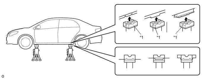
|
*1 | Rubber Attachment |
- | - |
(c) Set the jack and safety stands exactly under the specified locations on the vehicle.
Never set the jack or safety stands under suspension parts, such as a front lower arm, when jacking up the vehicle.
(d) Do not work on or leave the vehicle supported only by a jack. Be sure to support the vehicle with safety stands.
(e) When jacking up the vehicle, first release the parking brake and move the shift lever to N. (w/o Electronic Shift Lever System)
(f) When jacking up the vehicle, first release the parking brake, then move the shift lever to N and confirm that neutral (N) has been selected. (w/ Electronic Shift Lever System)
(g) When jacking up the entire vehicle:
(1) When jacking up the front wheels first, make sure wheel chocks are behind the rear wheels.
(2) When jacking up the rear wheels first, make sure wheel chocks are in front of the front wheels.
(h) When jacking up only the front or rear wheels of the vehicle:
(1) Before jacking up the front wheels, place wheel chocks on both sides of the rear wheels.
(2) Before jacking up the rear wheels, place wheel chocks on both sides of the front wheels.
(i) When lowering a vehicle that only has its front or rear wheels jacked up.
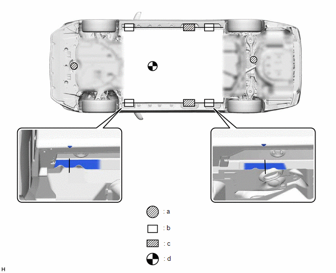
|
*a | JACK POSITION |
*b | SUPPORT POSITION - Safety stand - Swing arm type lift - Plate type lift (Front side) |
|
*c | SUPPORT POSITION - Plate type lift (Rear side) |
*d | VEHICLE CENTER OF GRAVITY (Unloaded Condition) |
(1) Before lowering the front wheels, make sure wheel chocks are in front of the rear wheels.
(2) Before lowering the rear wheels, make sure wheel chocks are behind the front wheels.
PRECAUTIONS FOR WHEN USING A SWING ARM TYPE LIFT
(a) Follow the safety procedures outlined in the lift's instruction manual.
(b) Use swing arms equipped with rubber attachments as shown in the illustration.
(c) Position the vehicle so that its center of gravity is centered on the lift (length of "L" in the illustration should be as short as possible).
(d) Ensure that the rubber cushions or swing arms do not contact the body cladding or lower mouldings.
(e) Be sure to lock the swing arms before raising the vehicle (if equipped with arm locks).
(f) Use the lift to raise the vehicle until the tires are off the ground, then stop the lift and shake the front and rear of the vehicle to make sure that it is stable.
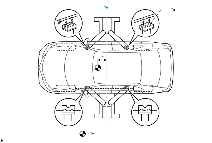
|
*a | Rubber Attachment |
*b | Center of lift |
|
*c | VEHICLE CENTER OF GRAVITY (Unloaded Condition) |
- | - |
PRECAUTIONS FOR WHEN USING A PLATE TYPE LIFT
(a) Follow the safety procedures outlined in the lift's instruction manual.
(b) Use plate lift attachments (rubber lifting blocks) on top of the plates.
(c) Be sure to set the vehicle to the specified position described in the following chart and shown in the following illustration.
|
Right and left set position | Center the vehicle on the lift. |
|
Front and rear set position |
|
(d) Ensure that the plate lift or rubber lifting blocks do not contact the body cladding or lower mouldings.
(e) Use the lift to raise the vehicle until the tires are off the ground, then stop the lift and shake the front and rear of the vehicle to make sure that it is stable.
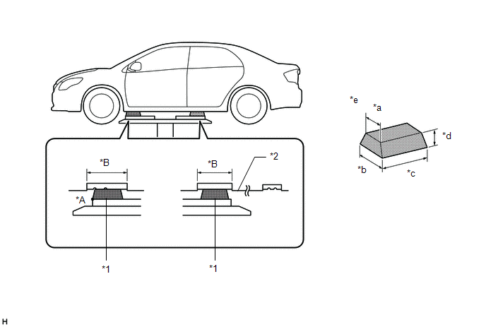
|
*1 | Attachment |
*2 | Rocker Panel Moulding |
|
*a | 85 mm (3.35 in.) |
*b | 100 mm (3.94 in.) |
|
*c | 200 mm (7.87 in.) |
*d | 70 mm (2.76 in.) |
|
*e | Attachment Dimensions |
- | - |
Toyota Avalon (XX50) 2019-2022 Service & Repair Manual > Audio And Visual System(for Hv Model): Main Body ECU Vehicle Information Reading/Writing Process Malfunction (B15F6). Certification ECU Vehicle Information Reading/Writing Process Malfunction (B15F7). XM Tuner Antenna Disconnected (B15FE,B
Main Body ECU Vehicle Information Reading/Writing Process Malfunction (B15F6) DESCRIPTION This DTC is stored when items controlled by the main body ECU (multiplex network body ECU) cannot be customized via the audio and visual system vehicle customization screen. HINT: The main body ECU (multiplex n ...

