COMPONENTS
ILLUSTRATION
|
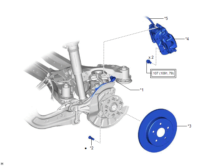
*1 | NO. 2 PARKING BRAKE WIRE ASSEMBLY |
*2 | REAR AXLE HUB BOLT |
|
*3 | REAR DISC |
*4 | REAR DISC BRAKE CALIPER ASSEMBLY |
|
*5 | REAR FLEXIBLE HOSE |
- | - |
 |
Tightening torque for "Major areas involving basic vehicle performance such as moving/turning/stopping": N*m (kgf*cm, ft.*lbf) |
● | Non-reusable part |
REPLACEMENT
CAUTION / NOTICE / HINT
The necessary procedures (adjustment, calibration, initialization, or registration) that must be performed after parts are removed and installed, or replaced during rear axle hub bolt removal/installation are shown below.
Necessary Procedures After Parts Removed/Installed/Replaced (for HV Model:)|
Replaced Part or Performed Procedure |
Necessary Procedure | Effect/Inoperative Function when Necessary Procedure not Performed |
Link |
|---|---|---|---|
|
*: When performing learning using the Techstream.
Click here | |||
|
Auxiliary battery terminal is disconnected/reconnected |
Perform steering sensor zero point calibration |
Lane Departure Alert System (w/ Steering Control) |
|
|
Pre-collision System | |||
|
Intelligent Clearance Sonar System* | |||
|
Lighting System (for HV Model with Cornering Light) | |||
|
Memorize steering angle neutral point |
Parking Assist Monitor System |
| |
|
Panoramic View Monitor System |
| ||
HINT:
PROCEDURE
1. PRECAUTION (for HV Model)
NOTICE:
After turning the power switch off, waiting time may be required before disconnecting the cable from the negative (-) auxiliary battery terminal. Therefore, make sure to read the disconnecting the cable from the negative (-) auxiliary battery terminal notices before proceeding with work.
Click here 
2. DISABLE BRAKE CONTROL (for HV Model)
Click here
3. REMOVE REAR WHEEL
Click here
4. DISCONNECT NO. 2 PARKING BRAKE WIRE ASSEMBLY
Click here
5. SEPARATE REAR DISC BRAKE CALIPER ASSEMBLY
(a) Remove the 2 bolts and separate the rear disc brake caliper assembly from the rear axle carrier sub-assembly.
NOTICE:
Use wire or an equivalent tool to keep the rear disc brake caliper assembly from hanging by the rear flexible hose.
6. REMOVE REAR DISC
Click here
7. REMOVE REAR AXLE HUB BOLT
| (a) Temporarily install 2 service nuts to the rear axle hub bolts as shown in the illustration. Recommended Service Nut: Thread diameter: 12.0 mm (0.472 in.) Thread pitch: 1.5 mm (0.0591 in.) NOTICE: Install the service nuts to prevent damage to the rear axle hub bolts. |
|
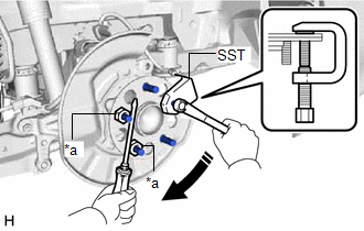
(b) Using SST and a screwdriver or an equivalent tool to hold the rear axle hub and bearing assembly, remove the rear axle hub bolt.
SST: 09628-10011
NOTICE:
Do not damage the threads of the rear axle hub bolts.
8. INSTALL REAR AXLE HUB BOLT
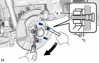
| (a) Temporarily install a new rear axle hub bolt to the rear axle hub and bearing assembly. |
|
(b) Install a washer and service nut to the rear axle hub bolt as shown in the illustration.
Recommended Service Nut:
Thread diameter: 12.0 mm (0.472 in.)
Thread pitch: 1.5 mm (0.0591 in.)
HINT:
Recommended washer thickness is 5 mm (0.197 in.) or more.
(c) Using a screwdriver or an equivalent tool to hold the rear axle hub and bearing assembly, install the rear axle hub bolt by tightening the service nut.
NOTICE:
(d) Remove the 3 service nuts and washer from the 3 rear axle hub bolts.
9. INSTALL REAR DISC
Click here
10. INSTALL REAR DISC BRAKE CALIPER ASSEMBLY
(a) Install the rear disc brake caliper assembly to the rear axle carrier sub-assembly with the 2 bolts.
Torque:
107 N·m {1091 kgf·cm, 79 ft·lbf}
11. CONNECT NO. 2 PARKING BRAKE WIRE ASSEMBLY
Click here
12. INSTALL REAR WHEEL
Click here
13. CONNECT CABLE TO NEGATIVE AUXILIARY BATTERY TERMINAL (for HV Model)
(a) Connect the reservoir level switch connector.
(b) Connect the cable to the negative (-) auxiliary battery terminal.
Click here
(c) Turn the power switch on (READY).
(d) Depress the brake pedal and release it.
(e) Clear the DTCs.
Click here
Toyota Avalon (XX50) 2019-2022 Service & Repair Manual > Can Communication System(for Hv Model): Check Bus 4 Line for Short to +B
DESCRIPTION There may be a short circuit between one of the CAN bus lines and +B when there is no resistance between terminal 22 (CA2H) of the central gateway ECU (network gateway ECU) and terminal 16 (BAT) of the DLC3, or terminal 7 (CA2L) of the central gateway ECU (network gateway ECU) and termin ...