COMPONENTS
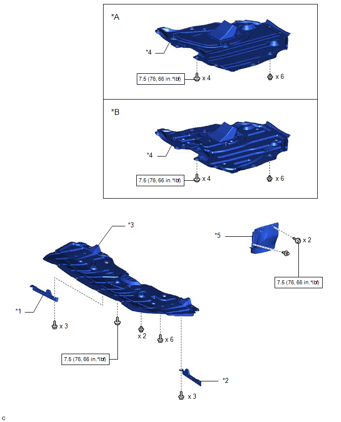
ILLUSTRATION
|
*A | Type A |
*B | Type B |
|
*1 | FRONT WHEEL OPENING EXTENSION PAD RH |
*2 | FRONT WHEEL OPENING EXTENSION PAD LH |
|
*3 | NO. 1 ENGINE UNDER COVER |
*4 | NO. 2 ENGINE UNDER COVER ASSEMBLY |
|
*5 | FRONT FENDER APRON SEAL LH |
- | - |
 |
N*m (kgf*cm, ft.*lbf): Specified torque |
- | - |
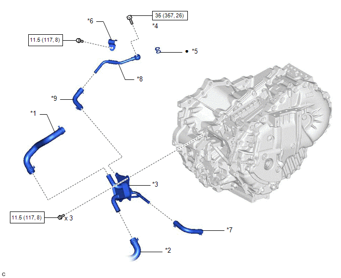
ILLUSTRATION
|
*1 | NO. 1 INVERTER COOLING HOSE |
*2 | NO. 5 INVERTER COOLING HOSE |
|
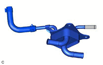
*3 | MOTOR COOLING COOLER |
*4 | OIL COOLER UNION BOLT |
|
*5 | GASKET |
*6 | NO. 1 OIL COOLER TUBE CLAMP |
|
*7 | NO. 1 MOTOR COOLING HOSE |
*8 | NO. 2 MOTOR COOLING PIPE |
|
*9 | NO. 2 MOTOR COOLING HOSE |
- | - |
|
|
N*m (kgf*cm, ft.*lbf): Specified torque |
● | Non-reusable part |
INSTALLATION
PROCEDURE
1. INSTALL NO. 1 MOTOR COOLING HOSE
HINT:
Perform this procedure only when replacement of the motor cooling cooler is necessary.
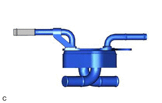
(a) Coat the pipe of the motor cooling cooler with a small amount of ATF as shown in the illustration.
 |
ATF Application Area |
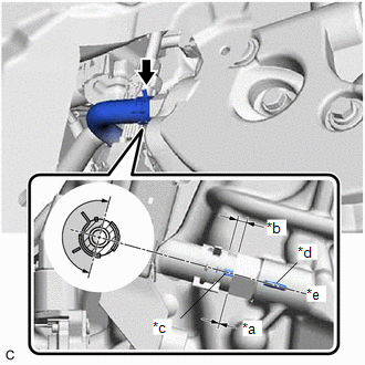
(b) Install the No. 1 motor cooling hose to the motor cooling cooler, and slide the clip to secure it.
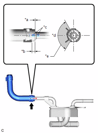
|
*a | 0 to 3 mm (0 to 0.118 in.) |
|
*b | 2 to 7 mm (0.0787 to 0.276 in.) |
|
*c | Paint Mark |
|
*d | Center of Paint Mark |
|
*e | 120° |
|
|
Claw of Clip Location |
NOTICE:
2. INSTALL NO. 2 MOTOR COOLING HOSE
HINT:
Perform this procedure only when replacement of the motor cooling cooler is necessary.
(a) Coat the pipe of the motor cooling cooler with a small amount of ATF as shown in the illustration.
|
|
ATF Application Area |
(b) Install the No. 2 motor cooling hose to the motor cooling cooler, and slide the clip to secure it.
|
*a | 0 to 3 mm (0 to 0.118 in.) |
|
*b | 2 to 7 mm (0.0787 to 0.276 in.) |
|
*c | Paint Mark |
|
*d | Center of Paint Mark |
|
*e | 120° |
|
|
Claw of Clip Location |
NOTICE:
3. INSTALL NO. 2 MOTOR COOLING PIPE
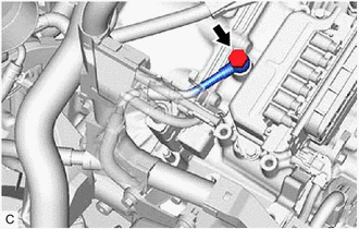
(a) Install the No. 2 motor cooling pipe to the No. 2 motor cooling hose, and slide the clip to secure it.
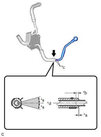
|
*a | 0 to 3 mm (0 to 0.118 in.) |
|
*b | 2 to 7 mm (0.0787 to 0.276 in.) |
|
*c | Paint Mark |
|
*d | Center of Paint Mark |
|
*e | 15° |
|
|
Center of Clip Location |
NOTICE:
4. INSTALL MOTOR COOLING COOLER
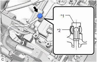
(a) Connect the No. 1 motor cooling hose to the transaxle housing tube connector, and slide the clip to secure it.
|
*a | 0 to 3 mm (0 to 0.118 in.) |
|
*b | 2 to 7 mm (0.0787 to 0.276 in.) |
|
*c | Paint Mark |
|
*d | Rib |
|
*e | Center of Rib |
|
*f | 180° |
|
|
Claw of Clip Location |
NOTICE:
| (b) Temporarily install the motor cooling cooler to the No. 1 transmission control cable bracket with the 3 bolts. |
|
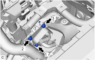
(c) Tighten the 3 bolts in the order shown in the illustration.
Torque:
11.5 N·m {117 kgf·cm, 8 ft·lbf}
| (d) Temporarily install the No. 2 motor cooling pipe to the hybrid vehicle transaxle assembly with the oil cooler union bolt and a new gasket. |
|
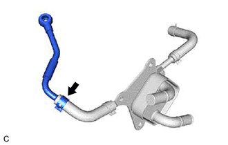
| (e) Install the No. 2 motor cooling pipe to the hose bracket with the bolt and No. 1 oil cooler tube clamp. Torque: 11.5 N·m {117 kgf·cm, 8 ft·lbf} |
|
| (f) Tighten the oil cooler union bolt. Torque: 35 N·m {357 kgf·cm, 26 ft·lbf} |
|
5. CONNECT NO. 5 INVERTER COOLING HOSE
Click here

6. INSTALL NO. 1 INVERTER COOLING HOSE
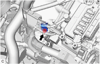
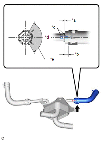
(a) Install the No. 1 inverter cooling hose to the motor cooling cooler, and slide the clip to secure it.
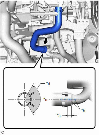
|
*a | 2 to 7 mm (0.0787 to 0.276 in.) |
|
*b | Paint Mark |
|
*c | Center of Paint Mark |
|
*d | 120° |
|
|
Claw of Clip Location |
NOTICE:
7. INSTALL INVERTER WITH CONVERTER ASSEMBLY
Click here
8. INSPECT HYBRID TRANSAXLE FLUID
Click here
9. INSPECT FOR HYBRID TRANSAXLE FLUID LEAK
10. INSTALL FRONT FENDER APRON SEAL LH
Click here
11. INSTALL NO. 2 ENGINE UNDER COVER ASSEMBLY
Click here
12. INSTALL NO. 1 ENGINE UNDER COVER
Click here
13. INSTALL FRONT WHEEL OPENING EXTENSION PAD LH
Click here
14. INSTALL FRONT WHEEL OPENING EXTENSION PAD RH
Click here
REMOVAL
CAUTION / NOTICE / HINT
The necessary procedures (adjustment, calibration, initialization, or registration) that must be performed after parts are removed and installed, or replaced during motor cooling cooler removal/installation are shown below.
Necessary Procedures After Parts Removed/Installed/Replaced|
Replaced Part or Performed Procedure |
Necessary Procedure | Effect/Inoperative Function when Necessary Procedure not Performed |
Link |
|---|---|---|---|
|
*: When performing learning using the Techstream.
Click here | |||
|
Auxiliary battery terminal is disconnected/reconnected |
Perform steering sensor zero point calibration |
Lane departure alert system (w/ Steering Control) |
|
|
Pre-collision system | |||
|
Intelligent clearance sonar system* | |||
|
Lighting system (w/ AFS)(EXT) | |||
|
Memorize steering angle neutral point |
Parking assist monitor system |
| |
|
Panoramic view monitor system |
| ||
|
Replacement of ECM | Perform Vehicle Identification Number (VIN) registration |
MIL illuminates |
|
|
Replacement of inverter with converter assembly |
Resolver learning |
|
|
CAUTION:
Click here 
NOTICE:
Click here
Click here
PROCEDURE
1. REMOVE FRONT WHEEL OPENING EXTENSION PAD RH
Click here
2. REMOVE FRONT WHEEL OPENING EXTENSION PAD LH
Click here
3. REMOVE NO. 1 ENGINE UNDER COVER
Click here
4. REMOVE NO. 2 ENGINE UNDER COVER ASSEMBLY
Click here
5. REMOVE FRONT FENDER APRON SEAL LH
Click here
6. REMOVE INVERTER WITH CONVERTER ASSEMBLY
Click here
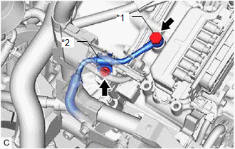
7. REMOVE NO. 1 INVERTER COOLING HOSE
| (a) Slide the clip and remove the No. 1 inverter cooling hose from the motor cooling cooler. |
|
8. DISCONNECT NO. 5 INVERTER COOLING HOSE
Click here
9. REMOVE MOTOR COOLING COOLER
| (a) Remove the oil cooler union bolt and gasket to disconnect the No. 2 motor cooling pipe from the hybrid vehicle transaxle assembly. |
|
(b) Remove the bolt and No. 1 oil cooler tube clamp to disconnect the No. 2 motor cooling pipe from the hose bracket.
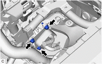
| (c) Remove the 3 bolts to disconnect the motor cooling cooler from the No. 1 transmission control cable bracket. |
|
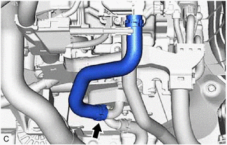
| (d) Slide the clip and disconnect the No. 1 motor cooling hose from the transaxle housing tube connector. NOTICE: Make sure not to remove the No. 1 motor cooling hose from the motor cooling cooler as the motor cooling cooler may be deformed. |
|
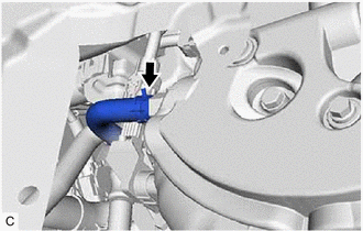
10. REMOVE NO. 2 MOTOR COOLING PIPE
| (a) Slide the clip and remove the No. 2 motor cooling pipe from the No. 2 motor cooling hose. NOTICE: Make sure not to remove the No. 2 motor cooling hose from the motor cooling cooler as the motor cooling cooler may be deformed. |
|
Toyota Avalon (XX50) 2019-2022 Service & Repair Manual > Can Communication System(for Hv Model): Radio Receiver Assembly Communication Stop Mode. Rear Television Camera Communication Stop Mode. Restraints Occupant Classification System Module Communication Stop Mode
Radio Receiver Assembly Communication Stop Mode DESCRIPTION Detection Item Symptom Trouble Area Radio Receiver Assembly Communication Stop Mode Any of the following conditions are met: Communication stop for "Display and Navigation (AVN)" is indicated on the "Communication Bus Check" screen of the T ...