DESCRIPTION The transmission revolution sensor (NT) detects the input shaft rotation speed and sends it to the ECM.
Based
on the transmission revolution sensor (NT) signal and the transmission
revolution sensor (NC) signals, the ECM controls engine torque and shift
timing. Based on the input shaft rotation speed and the engine speed
signal, lock-up control is performed. |
DTC No. | Detection Item |
DTC Detection Condition | Trouble Area |
MIL | Memory |
Note | | P071512 |
Input/Turbine Speed Sensor "A" Circuit Short to Battery |
All of the following conditions are met (1-trip detection logic):
- The battery voltage is 8 V or more.
- The engine switch is on (IG).
- The starter is off.
- Transmission revolution sensor (NT) input voltage is more than 1.9 V for 4.5 seconds.
|
- Transmission revolution sensor (NT)
- Transmission wire
- Harness and connector
- ECM
| Comes on |
DTC stored | SAE Code:
P07C0 | | P071514 |
Input/Turbine Speed Sensor "A" Circuit Short to Ground or Open |
All of the following conditions are met (1-trip detection logic):
- The battery voltage is 8 V or more.
- The engine switch is on (IG).
- The starter is off.
- Transmission revolution sensor (NT) input voltage is less than 0.1 V for 4.5 seconds or more.
|
- Transmission revolution sensor (NT)
- Transmission wire
- Harness and connector
- ECM
| Comes on |
DTC stored | SAE Code:
P07BF | | P071531 |
Input/Turbine Speed Sensor "A" No Signal |
All of the following conditions are met (1-trip detection logic):
- The battery voltage is 8 V or more.
- The park/neutral position switch D input signal is ON.
- The speed indicated by transmission revolution sensor (NC) is 520 rpm or more.
- The vehicle speed is 25 km/h (16 mph) or more.
- The vehicle is being driven in 1st, 2nd, 3rd, 4th, 5th, 6th, 7th or 8th gear.
- The speed indicated by transmission revolution sensor (NT) is less than 300 rpm for 5 seconds or more.
|
- Transmission revolution sensor (NT)
- Transmission wire
- Harness and connector
- ECM
| Comes on |
DTC stored | SAE Code:
P0717 | MONITOR DESCRIPTION
The
NT terminal of the ECM detects a pulse signal from the transmission
revolution sensor (NT) (input RPM). The ECM calculates gear shifts by
comparing input signals of the transmission revolution sensor (NT) with
the transmission revolution sensor (NC). While
the vehicle is being driven in 1st, 2nd, 3rd, 4th, 5th, 6th, 7th or 8th
gear with the shift lever in D, if the input shaft revolution (speed) is
less than 300 rpm* when the vehicle speed is 25 km/h (16 mph) or more,
the ECM interprets this as a malfunction, illuminates the MIL and stores
a DTC. *: Pulse is not output or is irregularly output. MONITOR STRATEGY |
Related DTCs | P0717: Speed sensor (NT)/Verify pulse input
P07BF: Speed sensor (NT)/Range check (Low voltage) P07C0: Speed sensor (NT)/Range check (High voltage) | |
Required sensors/components | Speed sensor (NT), Speed sensor (NC) | |
Frequency of operation | Continuous | |
Duration | P0717: 5 sec. P07BF, P07C0: 4.5 sec. | |
MIL operation | Immediate | |
Sequence of operation | None | TYPICAL ENABLING CONDITIONS All |
Battery voltage | 8 V or more | |
Engine switch | On (IG) | |
Starter | OFF | P0717 |
The monitor will run whenever the following DTCs are not stored |
None | | Turbine speed sensor range check fail (P07BF, P07C0)
(Pending / MIL) | Not detected | |
Vehicle speed sensor | 25 km/h (15.54 mph) or more | |
Intermediate shaft speed sensor revolution |
490 rpm or more | | Shift change is completed and before starting next shift change operation |
- | | Park/neutral position switch |
OFF | | R range position switch |
OFF | | D range position switch |
ON | | Engine |
Running | | Pressure
control solenoid circuit fail (P08C1, P08C2, P0962, P0963, P0966,
P0967, P0970, P0971, P2720, P2721, P2814, P2815, P281D, P281E) (Pending + MIL) |
Not detected | |
Torque converter clutch pressure control solenoid circuit fail (P2763, P2764)
(Pending + MIL) | Not detected | |
Torque converter clutch solenoid circuit fail (P2769, P2770) (Pending + MIL) |
Not detected | |
Vehicle speed sensor monitor condition is met |
- | P07BF, P07C0 |
The monitor will run whenever the following DTCs are not stored |
None | | Turbine speed sensor pulse input fail (P0717)
(Pending / MIL) | Not detected | Vehicle speed sensor monitor condition judgment: |
Intermediate shaft speed sensor revolution |
300 rpm or more | |
Shift change is completed and before starting next shift change operation |
- | | R range position switch |
OFF | | D range position switch |
ON | | Park/neutral position switch |
OFF | | Engine |
Running | | Pressure
control solenoid circuit fail (P08C1, P08C2, P0962, P0963, P0966,
P0967, P0970, P0971, P2720, P2721, P2814, P2815, P281D, P281E) (Pending + MIL) |
Not detected | |
Torque converter clutch pressure control solenoid circuit fail (P2763, P2764)
(Pending + MIL) | Not detected | |
Torque converter clutch solenoid circuit fail (P2769, P2770) (Pending + MIL) |
Not detected | One of the following conditions is met: Condition (A), (B), (C), (D), (E), (F), (G) or (H)
- Condition (A)
|
ECM selected gear |
1st |
|
Turbine speed sensor revolution |
1450 rpm or more |
Condition (B)
|
ECM selected gear |
2nd |
|
Turbine speed sensor revolution |
840 rpm or more |
Condition (C)
|
ECM selected gear |
3rd |
|
Turbine speed sensor revolution |
540 rpm or more |
Condition (D)
|
ECM selected gear |
4th |
|
Turbine speed sensor revolution |
400 rpm or more |
Condition (E)
|
ECM selected gear |
5th |
|
Turbine speed sensor revolution |
330 rpm or more |
Condition (F)
|
ECM selected gear |
6th |
|
Turbine speed sensor revolution |
300 rpm or more |
Condition (G)
|
ECM selected gear |
7th |
|
Turbine speed sensor revolution |
300 rpm or more |
Condition (H)
|
ECM selected gear |
8th |
|
Turbine speed sensor revolution |
300 rpm or more |
Either of the following conditions is met: Condition (I) or (J)
- Condition (I)
|
ECT |
20°C (68°F) or more |
|
ECT sensor circuit fail (P0117, P0118)
(Pending + MIL) |
Not detected |
|
Time after park/neutral position switch ON to OFF |
2 sec. or more |
Condition (J)
|
Either of the following conditions is met |
(a) or (b) |
|
(a) ECT |
Less than 20°C (68°F) |
|
(b) ECT sensor circuit fail (P0117, P0118)
(Pending + MIL) |
Detected |
|
Time after park/neutral position switch ON to OFF |
30 sec. or more |
TYPICAL MALFUNCTION THRESHOLDS P0717 |
Turbine speed sensor revolution | Less than 300 rpm | P07BF |
Turbine speed sensor voltage | Less than 0.1 V | P07C0 |
Turbine speed sensor voltage | More than 1.9 V | COMPONENT OPERATING RANGE |
Turbine speed sensor revolution | 300 rpm or more | |
Turbine speed sensor voltage | 0.1 V or more and 1.9 V or less | CONFIRMATION DRIVING PATTERN
CAUTION: When performing the D Position Shift Test inspection in Road Test, obey all speed limits and traffic laws.
HINT:
- After repairs have been completed, clear the DTCs and then check that
the vehicle has returned to normal by performing the following All
Readiness check procedure.
- When clearing the permanent DTCs, refer to the Clear Permanent DTC procedure.
Click here 
- Connect the Techstream to the DLC3.
- Turn the engine switch on (IG) and turn the Techstream on.
- Clear the DTCs (even if no DTCs are stored, perform the clear DTC procedure).
- Turn the engine switch off and wait for 2 minutes or more.
- Turn the engine switch on (IG) and turn the Techstream on.
- Start the engine.
- Perform the D Position Shift Test inspection in Road Test. [*1]
Click here
HINT:
[*1] : Normal judgment procedure.
The normal judgment procedure is used to complete DTC judgment and also used when clearing permanent DTCs.
- Stop the vehicle.
- Enter the following menus: Powertrain / Transmission / Utility / All Readiness.
- Input the DTC: P071512, P071514 or P071531.
- Check the DTC judgment result.
|
Techstream Display |
Description |
|
NORMAL |
- DTC judgment completed
- System normal
|
|
ABNORMAL |
- DTC judgment completed
- System abnormal
|
|
INCOMPLETE |
- DTC judgment not completed
- Perform driving pattern after confirming DTC enabling conditions
|
|
N/A |
- Unable to perform DTC judgment
- Number of DTCs which do not fulfill DTC preconditions has reached ECU memory limit
|
HINT:
- If the judgment result shows NORMAL, the system is normal.
- If the judgment result shows ABNORMAL, the system has a malfunction.
- If the judgment result shows INCOMPLETE or N/A, perform the normal judgment procedure again.
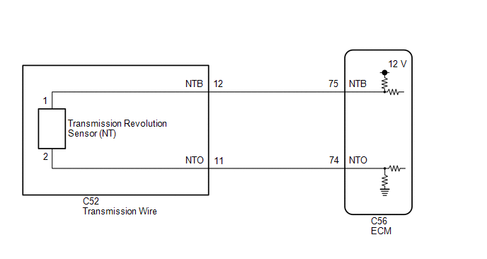
WIRING DIAGRAM
 CAUTION / NOTICE / HINT
CAUTION:
- Strictly observe posted speed, limits, traffic laws and road conditions.
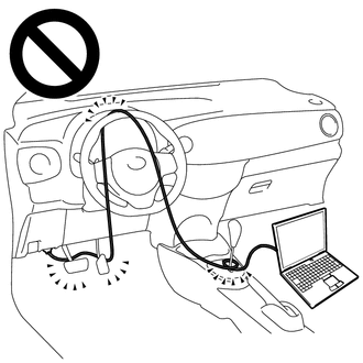
- Do not drive the vehicle with the cable of the Techstream contacting the pedals, shift lever or steering wheel.
- Driving the vehicle with the cable of the Techstream contacting these
areas could impede vehicle control, resulting in a serious accident.
- Do not operate the Techstream while driving the vehicle.
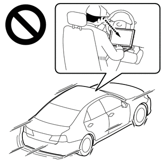
- Operating the Techstream while driving the vehicle will prevent you from
paying sufficient attention to vehicle surroundings, and could result
in a serious accident.
NOTICE:
- Perform the universal trip to clear permanent DTCs.
Click here
- Perform registration and/or initialization when parts related to the automatic transaxle are replaced.
Click here
DATA LIST NOTICE: In
the table below, the values listed under "Normal Condition" are
reference values. Do not depend solely on these reference values when
deciding whether a part is faulty or not. HINT: Using
the Techstream to read the Data List allows the values or states of
switches, sensors, actuators and other items to be read without removing
any parts. This non-intrusive inspection can be very useful because
intermittent conditions or signals may be discovered before parts or
wiring is disturbed. Reading the Data List information early in
troubleshooting is one way to save diagnostic time. (a) Warm up the engine.
(b) Turn the engine switch off. (c) Connect the Techstream to the DLC3.
(d) Turn the engine switch on (IG). (e) Turn the Techstream on.
(f) Enter the following menus: Powertrain / Transmission / Data List / NT Sensor Speed.
(g) Read the Data List according to the display on the Techstream. Powertrain > Transmission > Data List
|
Tester Display | Measurement Item |
Range | Normal Condition |
Diagnostic Note | |
NT Sensor Speed | Input shaft speed |
Min.: 0 rpm Max.: 12750 rpm |
- Equal to engine speed: Lock-up on (after warming up engine)
- Nearly equal to engine speed: Lock-up off (idling with shift lever in N)
| Data is displayed in increments of 50 rpm | Powertrain > Transmission > Data List
|
Tester Display | | NT Sensor Speed |
HINT:
- NT Sensor Speed is always 0 while driving: Open or short in the sensor or circuit.
- NT Sensor Speed is always more than 0 and less than 300 rpm while
driving the vehicle at 50 km/h (31 mph) or more: Sensor malfunction,
improper installation, or intermittent connection malfunction in the
circuit.
PROCEDURE |
1. | READ VALUE USING TECHSTREAM |
(a) Connect the Techstream to the DLC3. (b) Turn the engine switch on (IG).
(c) Turn the Techstream on. (d) Enter the following menus: Powertrain / Transmission / Data List / NT Sensor Speed and NT Sensor Voltage.
(e) Read the Data List according to the display on the Techstream. Powertrain > Transmission > Data List
|
Tester Display | Measurement Item |
Range | Normal Condition |
Diagnostic Note | |
NT Sensor Speed | Input shaft speed |
Min.: 0 rpm Max.: 12750 rpm |
- Equal to engine speed: Lock-up on (after warming up engine)
- Nearly equal to engine speed: Lock-up off (idling with shift lever in N)
| Data is displayed in increments of 50 rpm | |
NT Sensor Voltage | NT sensor voltage |
Min.: 0.000 V Max.: 4.999 V |
0.1 to 1.9 V: Engine idling |
- | Powertrain > Transmission > Data List
|
Tester Display | | NT Sensor Speed | |
NT Sensor Voltage |
|
Result | Proceed to | |
Data List values are normal |
A | | Data List values are not normal |
B |
| A |
 | GO TO STEP 5 |
|
B |
 | |
| 2. |
INSPECT TRANSMISSION REVOLUTION SENSOR (NT) |
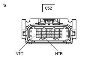
| (a) Disconnect the C52 transmission wire connector. |
 |
|
*a | Front view of wire harness connector
(to Transmission Wire) | | |
(b) Measure the resistance according to the value(s) in the table below. Standard Resistance: |
Tester Connection | Condition |
Specified Condition | | C52-11 (NTO) - Body ground |
Always | 99 to 101 Ω |
(c) Turn the engine switch on (IG). (d) Measure the voltage according to the value(s) in the table below.
Standard Voltage: |
Tester Connection | Condition |
Specified Condition | | C52-12 (NTB) - Body ground |
Engine switch on (IG) |
11 to 14 V |
| NG |
| GO TO STEP 4 |
|
OK | |
| |
| 3. |
INSPECT TRANSMISSION WIRE (TRANSMISSION REVOLUTION SENSOR (NT)) |
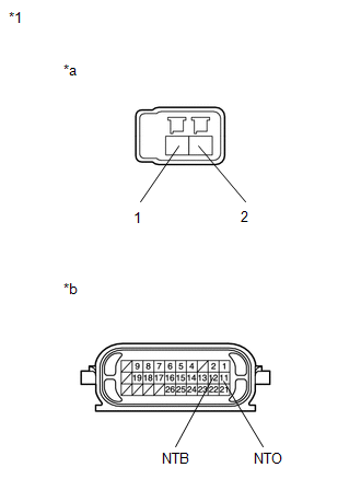
| (a) Disconnect the transmission revolution sensor (NT) connector.
Click here |
 |
|
*1 | Transmission Wire | |
*a | Transmission Revolution Sensor (NT) Side | |
*b | Wire Harness Connector Side | | |
(b) Disconnect the C52 transmission wire connector. (c) Measure the resistance according to the value(s) in the table below. Standard Resistance |
Tester Connection | Condition |
Specified Condition | |
1 (transmission revolution sensor (NT) side) - 12 (NTB) (wire harness connector side) |
Always | Below 1 Ω | |
2 (transmission revolution sensor (NT) side) - 11 (NTO) (wire harness connector side) |
Always | Below 1 Ω | |
1 (transmission revolution sensor (NT) side) or 12 (NTB) (wire harness connector side) - Body ground and other terminals |
Always | 10 kΩ or higher | |
2 (transmission revolution sensor (NT) side) or 11 (NTO) (wire harness connector side) - Body ground and other terminals |
Always | 10 kΩ or higher |
| OK |
| REPLACE TRANSMISSION REVOLUTION SENSOR (NT) |
| NG |
| REPAIR OR REPLACE TRANSMISSION WIRE |
| 4. |
CHECK HARNESS AND CONNECTOR (TRANSMISSION WIRE - ECM) |
(a) Disconnect the C52 transmission wire connector. (b) Disconnect the C56 ECM connector.
(c) Measure the resistance according to the value(s) in the table below.
Standard Resistance: |
Tester Connection | Condition |
Specified Condition | | C52-12 (NTB) - C56-75 (NTB) |
Always | Below 1 Ω | |
C52-11 (NTO) - C56-74 (NTO) |
Always | Below 1 Ω | |
C52-12 (NTB) or C56-75 (NTB) - Body ground and other terminals |
Always | 10 kΩ or higher | |
C52-11 (NTO) or C56-74 (NTO) - Body ground and other terminals |
Always | 10 kΩ or higher |
| NG |
| REPAIR OR REPLACE HARNESS OR CONNECTOR (TRANSMISSION WIRE - ECM) |
|
OK | |
| |
(a) Replace the ECM.
Click here
| NEXT |
| PERFORM REGISTRATION | |


