DESCRIPTION
Changing gears is performed by the ECM turning the solenoid (SL1, SL2, SL3, SL4, SL5 and SL6) valves on and off.
If an open or short occurs in any of the solenoid valve circuits, the ECM controls the remaining normal solenoid valves to allow the vehicle to be driven. If all of the solenoid valves are malfunctioning, only the mechanical fluid pressure circuit will function and some manual operation will be possible. If an open or short occurs in a solenoid valve circuit, the ECM cuts power to the malfunctioning solenoid valve.
HINT:
The following table shows normal operation of the solenoid (SL3) valve when the shift lever is in D.
Solenoid Valve Operation:|
Gear | 1st |
2nd | 3rd |
4th | 5th |
6th | 7th |
8th |
|---|---|---|---|---|---|---|---|---|
| Solenoid (SL3) Valve |
OFF | OFF |
ON | OFF |
OFF | OFF |
ON | OFF |
|
DTC No. | Detection Item |
DTC Detection Condition | Trouble Area |
MIL | Memory |
Note |
|---|---|---|---|---|---|---|
| P079512 |
Pressure Control Solenoid "C" Circuit Short to Battery |
While the vehicle is being driven so that gear changes occur, a short to +B is detected in the solenoid (SL3) valve circuit for 1 second (1-trip detection logic). |
| Comes on |
DTC stored | SAE Code: P0971 |
MONITOR DESCRIPTION
This DTC indicates a short to +B in the solenoid (SL3) valve circuit. The ECM commands gear shifts by turning the solenoid valves on or off. When there is an open or short in any solenoid valve circuit, the ECM detects the problem, illuminates the MIL and stores a DTC.
The ECM performs the fail-safe function and turns the other normal solenoid valves on or off. In the case of an open or short circuit, the ECM stops sending current to the open or shorted solenoid.
MONITOR STRATEGY
|
Related DTCs | P0971: Solenoid (SL3) valve/Range check (High current) |
|
Required sensors/components | Solenoid (SL3) valve |
|
Frequency of operation | Continuous |
|
Duration | 1 sec. |
|
MIL operation | Immediate |
|
Sequence of operation | None |
TYPICAL ENABLING CONDITIONS
All|
The monitor will run whenever the following DTCs are not stored |
None |
| Solenoid current cut status |
Not cut |
| Engine switch |
On (IG) |
| Starter |
OFF |
| Battery voltage |
10.5 V or more |
|
Battery voltage | 8 V or more and less than 12.499 V |
|
Target current (0.1 sec. or more) | 0.8 A or less |
|
Battery voltage | 12.5 V or more and less than 16 V |
|
Target current (0 sec. or more) | 1 A or less |
TYPICAL MALFUNCTION THRESHOLDS
Any of the following conditions are met: Condition (A) or (B)
Condition (A)|
Battery voltage | 8 V or more and less than 12.499 V |
|
Solenoid current | More than 0.92 A |
|
Battery voltage | 12.5 V or more and less than 16 V |
|
Solenoid current | More than 1.1 A |
COMPONENT OPERATING RANGE
Both of the following conditions are met: Condition (A) and (B)
Condition (A)|
Battery voltage | 8 V or more and less than 12.499 V |
|
Solenoid current | 0.92 A or less |
|
Battery voltage | 12.5 V or more and less than 16 V |
|
Solenoid current | 1.1 A or less |
CONFIRMATION DRIVING PATTERN
CAUTION:
When performing the confirmation driving pattern, obey all speed limits and traffic laws.
HINT:
Click here 
Click here
HINT:
[*1] : Normal judgment procedure.
The normal judgment procedure is used to complete DTC judgment and also used when clearing permanent DTCs.
|
Techstream Display |
Description |
|---|---|
|
NORMAL |
|
|
ABNORMAL |
|
|
INCOMPLETE |
|
|
N/A |
|
HINT:
WIRING DIAGRAM
CAUTION / NOTICE / HINT
NOTICE:
Click here
Click here
PROCEDURE
|
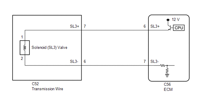
1. | CHECK HARNESS AND TRANSMISSION WIRE (TRANSMISSION WIRE (SOLENOID (SL3) VALVE) - ECM) |
(a) Disconnect the C56 ECM connector.
(b) Measure the resistance according to the value(s) in the table below.
Standard Resistance:
|
Tester Connection | Condition |
Specified Condition |
|---|---|---|
|
C56-6 (SL3+) or C56-7 (SL3-) - Other terminals |
Always | 10 kΩ or higher |
| NG |  | GO TO STEP 3 |
|
| 2. |
REPLACE ECM |
(a) Replace the ECM.
Click here
| NEXT | | PERFORM REGISTRATION |
| 3. |
CHECK HARNESS AND CONNECTOR (TRANSMISSION WIRE - ECM) |
(a) Disconnect the C52 transmission wire connector.
(b) Disconnect the C56 ECM connector.
(c) Measure the resistance according to the value(s) in the table below.
Standard Resistance:
|
Tester Connection | Condition |
Specified Condition |
|---|---|---|
|
C52-7 (SL3+) or C56-6 (SL3+) - Other terminals |
Always | 10 kΩ or higher |
|
C52-6 (SL3-) or C56-7 (SL3-) - Other terminals |
Always | 10 kΩ or higher |
| NG | | REPAIR OR REPLACE HARNESS OR CONNECTOR (TRANSMISSION WIRE - ECM) |
|
| 4. |
INSPECT SOLENOID (SL3) VALVE |
| (a) Remove the solenoid (SL3) valve. Click here
|
|
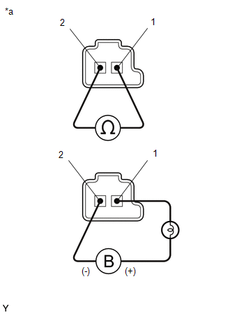
(b) Measure the resistance according to the value(s) in the table below.
Standard Resistance:
|
Tester Connection | Condition |
Specified Condition |
|---|---|---|
|
Solenoid (SL3) valve connector terminal 1 - terminal 2 |
20°C (68°F) | 5.0 to 5.6 Ω |
(c) Connect a positive (+) lead from the battery with a 21 W bulb to terminal 1 and a negative (-) lead to terminal 2 of the solenoid valve connector. Check that the valve moves and makes an operating sound.
OK:
Valve moves and makes an operating sound.
| OK | | REPAIR OR REPLACE TRANSMISSION WIRE |
| NG | | REPLACE SOLENOID (SL3) VALVE |
DESCRIPTION
Refer to DTC P079512.
Click here

|
DTC No. | Detection Item |
DTC Detection Condition | Trouble Area |
MIL | Memory |
Note |
|---|---|---|---|---|---|---|
| P079514 |
Pressure Control Solenoid "C" Circuit Short to Ground or Open |
While the vehicle is being driven so that gear changes occur, a short to ground or open is detected in the solenoid (SL3) valve circuit for 1 second (1-trip detection logic). |
| Comes on |
DTC stored | SAE Code: P0970 |
MONITOR DESCRIPTION
This DTC indicates an open or short to ground in the solenoid (SL3) valve circuit. The ECM commands gear shifts by turning the solenoid valves on or off. When there is an open or short in any solenoid valve circuit, the ECM detects the problem, illuminates the MIL and stores a DTC.
The ECM performs the fail-safe function and turns the other normal solenoid valves on or off. In the case of an open or short circuit, the ECM stops sending current to the open or shorted solenoid.
MONITOR STRATEGY
|
Related DTCs | P0970: Solenoid (SL3) valve/Range check (Low current) |
|
Required sensors/components | Solenoid (SL3) valve |
|
Frequency of operation | Continuous |
|
Duration | 1 sec. |
|
MIL operation | Immediate |
|
Sequence of operation | None |
TYPICAL ENABLING CONDITIONS
|
The monitor will run whenever the following DTCs are not stored |
None |
| Solenoid current cut status |
Not cut |
| Engine switch |
On (IG) |
| Starter |
OFF |
| Battery voltage |
10.5 V or more |
|
Target current (0.1 sec. or more) |
0.2 A or more |
TYPICAL MALFUNCTION THRESHOLDS
|
Solenoid current | Less than 0.075 A |
COMPONENT OPERATING RANGE
|
Solenoid current | 0.075 A or more |
CONFIRMATION DRIVING PATTERN
CAUTION:
When performing the confirmation driving pattern, obey all speed limits and traffic laws.
HINT:
Click here
Click here
HINT:
[*1] : Normal judgment procedure.
The normal judgment procedure is used to complete DTC judgment and also used when clearing permanent DTCs.
|
Techstream Display |
Description |
|---|---|
|
NORMAL |
|
|
ABNORMAL |
|
|
INCOMPLETE |
|
|
N/A |
|
HINT:
WIRING DIAGRAM
Refer to DTC P079512.
Click here
CAUTION / NOTICE / HINT
NOTICE:
Click here
Click here
PROCEDURE
|
1. | CHECK HARNESS AND TRANSMISSION WIRE (TRANSMISSION WIRE (SOLENOID (SL3) VALVE) - ECM) |
(a) Disconnect the C56 ECM connector.
(b) Measure the resistance according to the value(s) in the table below.
Standard Resistance:
|
Tester Connection | Condition |
Specified Condition |
|---|---|---|
|
C56-6 (SL3+) - C56-7 (SL3-) |
20°C (68°F) | 5.0 to 5.6 Ω |
|
C56-6 (SL3+) or C56-7 (SL3-) - Body ground and other terminals |
Always | 10 kΩ or higher |
| NG |  | GO TO STEP 3 |
|
| 2. |
REPLACE ECM |
(a) Replace the ECM.
Click here
| NEXT | | PERFORM REGISTRATION |
| 3. |
CHECK HARNESS AND CONNECTOR (TRANSMISSION WIRE - ECM) |
(a) Disconnect the C52 transmission wire connector.
(b) Disconnect the C56 ECM connector.
(c) Measure the resistance according to the value(s) in the table below.
Standard Resistance:
|
Tester Connection | Condition |
Specified Condition |
|---|---|---|
|
C52-7 (SL3+) - C56-6 (SL3+) |
Always | Below 1 Ω |
|
C52-6 (SL3-) - C56-7 (SL3-) |
Always | Below 1 Ω |
|
C52-7 (SL3+) or C56-6 (SL3+) - Body ground and other terminals |
Always | 10 kΩ or higher |
|
C52-6 (SL3-) or C56-7 (SL3-) - Body ground and other terminals |
Always | 10 kΩ or higher |
| NG | | REPAIR OR REPLACE HARNESS OR CONNECTOR (TRANSMISSION WIRE - ECM) |
|
| 4. |
INSPECT SOLENOID (SL3) VALVE |
| (a) Remove the solenoid (SL3) valve. Click here
|
|
(b) Measure the resistance according to the value(s) in the table below.
Standard Resistance:
|
Tester Connection | Condition |
Specified Condition |
|---|---|---|
|
Solenoid (SL3) valve connector terminal 1 - terminal 2 |
20°C (68°F) | 5.0 to 5.6 Ω |
(c) Connect a positive (+) lead from the battery with a 21 W bulb to terminal 1 and a negative (-) lead to terminal 2 of the solenoid valve connector. Check that the valve moves and makes an operating sound.
OK:
Valve moves and makes an operating sound.
| OK | | REPAIR OR REPLACE TRANSMISSION WIRE |
| NG | | REPLACE SOLENOID (SL3) VALVE |
DESCRIPTION
Refer to DTC P27137F.
Click here

|
DTC No. | Detection Item |
DTC Detection Condition | Trouble Area |
MIL | Memory |
Note |
|---|---|---|---|---|---|---|
| P271312 |
Pressure Control Solenoid "D" Circuit Short to Battery |
While the engine is running, a short to +B is detected in the solenoid (SLT) valve circuit for 1 second (1-trip detection logic). |
| Comes on |
DTC stored | SAE Code: P2721 |
MONITOR DESCRIPTION
When a short to +B in the solenoid (SLT) valve circuit is detected, the ECM will determine that there is a malfunction, illuminate the MIL and store this DTC.
MONITOR STRATEGY
|
Related DTC | P2721: Solenoid (SLT) valve/Range check (High current) P2721: Solenoid (SLT) valve/Range check (High voltage) |
|
Required sensors/components |
Solenoid (SLT) valve |
|
Frequency of operation |
Continuous |
| Duration |
High current: 1 sec. High voltage: 1.3 sec. |
|
MIL operation | Immediate |
|
Sequence of operation | None |
TYPICAL ENABLING CONDITIONS
All|
The monitor will run whenever the following DTCs are not stored |
None |
| Solenoid current cut status |
Not cut |
| Engine switch |
On (IG) |
| Starter |
OFF |
| Battery voltage |
10.5 V or more |
|
Battery voltage | 8 V or more and less than 12.499 V |
|
Target current (0.1 sec. or more) | 0.8 A or less |
|
Battery voltage | 12.5 V or more and less than 16 V |
|
Target current (0 sec. or more) | 1 A or less |
|
Target current | 0.2 A or more |
|
Output duty cycle | 10% or more and 90% or less |
TYPICAL MALFUNCTION THRESHOLDS
High current:|
Battery voltage |
8 V or more and less than 12.499 V |
|
Solenoid current |
More than 0.92 A |
|
Battery voltage |
12.5 V or more and less than 16 V |
|
Solenoid current |
More than 1.1 A |
|
Solenoid voltage monitor | No signal |
COMPONENT OPERATING RANGE
High current|
Both of the following conditions are met |
(a) or (b) |
| (a) Battery voltage |
8 V or more and less than 12.499 V |
|
Solenoid current | 0.92 A or less |
|
(b) Battery voltage | 12.5 V or more and less than 16 V |
|
Solenoid current | 1.1 A or less |
|
Solenoid voltage monitor | Signal input |
CONFIRMATION DRIVING PATTERN
HINT:
Click here
HINT:
[*1] : Normal judgment procedure.
The normal judgment procedure is used to complete DTC judgment and also used when clearing permanent DTCs.
|
Techstream Display |
Description |
|---|---|
|
NORMAL |
|
|
ABNORMAL |
|
|
INCOMPLETE |
|
|
N/A |
|
HINT:
WIRING DIAGRAM
CAUTION / NOTICE / HINT
NOTICE:
Click here
Click here
PROCEDURE
|
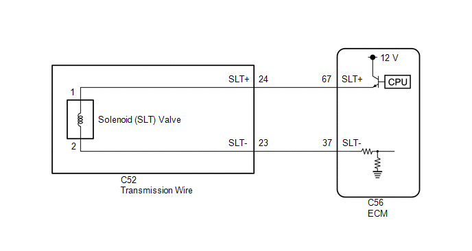
1. | CHECK HARNESS AND CONNECTOR (TRANSMISSION WIRE (SOLENOID (SLT) VALVE) - ECM) |
(a) Disconnect the C56 ECM connector.
(b) Measure the resistance according to the value(s) in the table below.
Standard Resistance:
|
Tester Connection | Condition |
Specified Condition |
|---|---|---|
|
C56-67 (SLT+) or C56-37 (SLT-) - Other terminals |
Always | 10 kΩ or higher |
| NG |  | GO TO STEP 3 |
|
| 2. |
REPLACE ECM |
(a) Replace the ECM.
Click here
| NEXT | | PERFORM REGISTRATION |
| 3. |
CHECK HARNESS AND CONNECTOR (TRANSMISSION WIRE - ECM) |
(a) Disconnect the C52 transmission wire connector.
(b) Disconnect the C56 ECM connector.
(c) Measure the resistance according to the value(s) in the table below.
Standard Resistance:
|
Tester Connection | Condition |
Specified Condition |
|---|---|---|
|
C52-24 (SLT+) or C56-67 (SLT+) - Other terminals |
Always | 10 kΩ or higher |
|
C52-23 (SLT-) or C56-37 (SLT-) - Other terminals |
Always | 10 kΩ or higher |
| NG | | REPAIR OR REPLACE HARNESS OR CONNECTOR (TRANSMISSION WIRE - ECM) |
|
| 4. |
INSPECT SOLENOID (SLT) VALVE |
| (a) Remove the solenoid (SLT) valve. Click here
|
|
(b) Measure the resistance according to the value(s) in the table below.
Standard Resistance:
|
Tester Connection | Condition |
Specified Condition |
|---|---|---|
|
Solenoid (SLT) valve connector terminal 1 - terminal 2 |
20°C (68°F) | 5.0 to 5.6 Ω |
(c) Connect a positive (+) lead from the battery with a 21 W bulb to terminal 1 and a negative (-) lead to terminal 2 of the solenoid valve connector. Check that the valve moves and makes an operating sound.
OK:
Valve moves and makes an operating sound.
| OK | | REPAIR OR REPLACE TRANSMISSION WIRE |
| NG | | REPLACE SOLENOID (SLT) VALVE |
Toyota Avalon (XX50) 2019-2022 Service & Repair Manual > 2gr-fks Intake / Exhaust: Air Cleaner Filter Element
ComponentsCOMPONENTS ILLUSTRATION *1 AIR CLEANER CAP SUB-ASSEMBLY *2 AIR CLEANER FILTER ELEMENT SUB-ASSEMBLY InstallationINSTALLATION PROCEDURE 1. INSTALL AIR CLEANER FILTER ELEMENT SUB-ASSEMBLY Click here 2. INSTALL AIR CLEANER CAP SUB-ASSEMBLY Click here RemovalREMOVAL PROCEDURE 1. SEPARATE AIR C ...