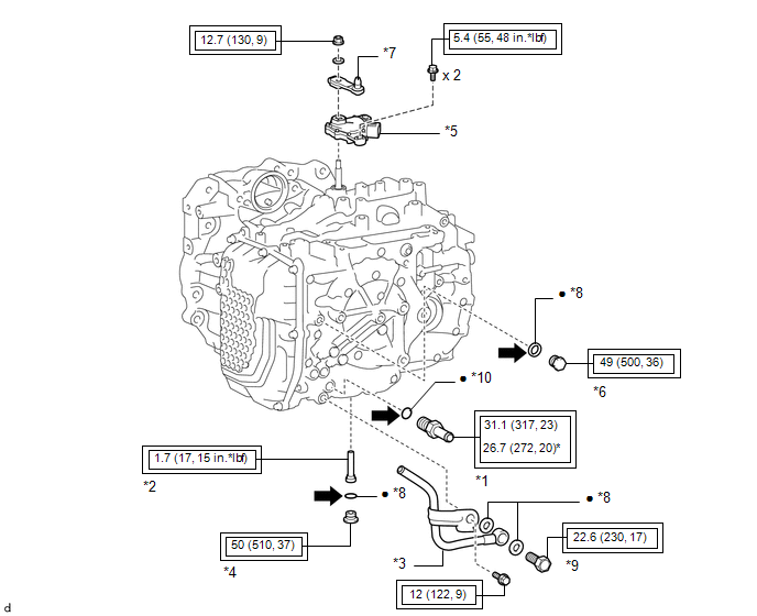
COMPONENTS
ILLUSTRATION
|
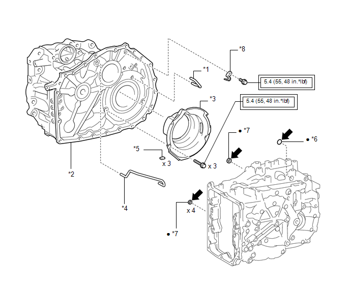
*1 | NO. 1 OIL COOLER OUTLET TUBE SUB-ASSEMBLY |
*2 | NO. 1 TRANSMISSION OIL FILLER TUBE |
|
*3 | OIL COOLER UNION SUB-ASSEMBLY |
*4 | OVERFLOW PLUG |
|
*5 | PARK/NEUTRAL POSITION SWITCH ASSEMBLY |
*6 | REFILL PLUG |
|
*7 | TRANSMISSION CONTROL SHAFT LEVER |
*8 | GASKET |
|
*9 | OIL COOLER UNION BOLT |
*10 | O-RING |
 |
Tightening torque for "Major areas involving basic vehicle performance such as moving/turning/stopping": N*m (kgf*cm, ft.*lbf) |
* | For use with a union nut wrench |
|
● | Non-reusable part |
 |
Toyota Genuine ATF WS |
ILLUSTRATION
|
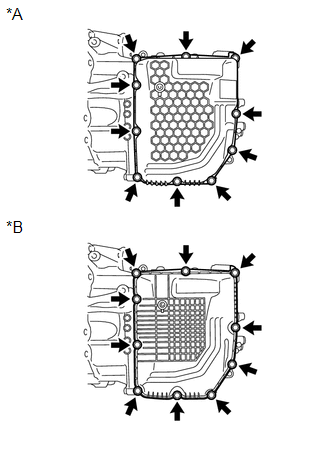
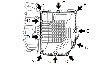
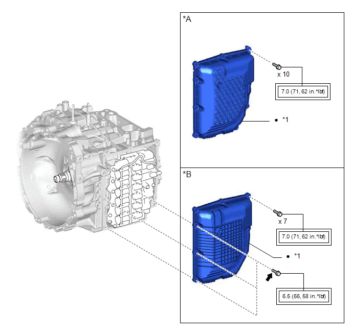
*A | for TMC Made |
*B | for TMMWV Made |
|
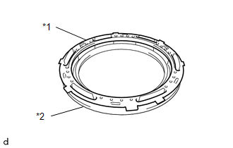
*1 | TRANSMISSION CASE SIDE COVER |
- | - |
|
|
Tightening torque for "Major areas involving basic vehicle performance such as moving/turning/stopping": N*m (kgf*cm, ft.*lbf) |
● | Non-reusable part |
|
|
Toyota Genuine Adhesive 1324, Three Bond 1324 or equivalent |
★ | Precoated part |
ILLUSTRATION
|
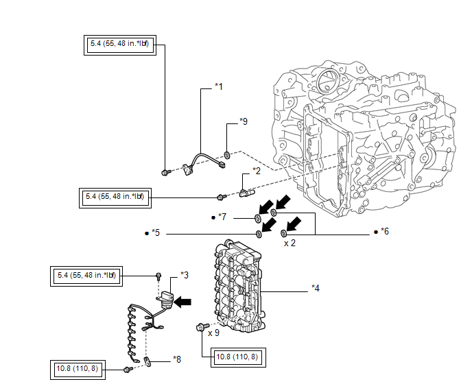
*1 | TRANSMISSION REVOLUTION SENSOR (NC) |
*2 | TRANSMISSION REVOLUTION SENSOR (NT) |
|
*3 | TRANSMISSION WIRE |
*4 | TRANSMISSION VALVE BODY ASSEMBLY |
|
*5 | NO. 1 FRONT OIL PUMP COVER GASKET |
*6 | TRANSAXLE CASE GASKET |
|
*7 | NO. 2 FRONT OIL PUMP COVER GASKET |
*8 | TEMPERATURE SENSOR CLAMP |
|
*9 | SPACER |
- | - |
|
|
Tightening torque for "Major areas involving basic vehicle performance such as moving/turning/stopping": N*m (kgf*cm, ft.*lbf) |
● | Non-reusable part |
|
|
Toyota Genuine ATF WS |
- | - |
ILLUSTRATION
|
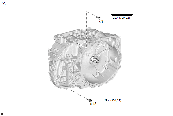
*A | for TMC Made |
- | - |
|
|
Tightening torque for "Major areas involving basic vehicle performance such as moving/turning/stopping": N*m (kgf*cm, ft.*lbf) |
- | - |
ILLUSTRATION
|
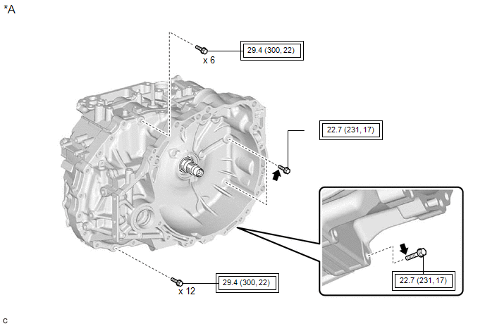
*A | for TMMWV Made |
- | - |
|
|
Tightening torque for "Major areas involving basic vehicle performance such as moving/turning/stopping": N*m (kgf*cm, ft.*lbf) |
|
Toyota Genuine Adhesive 1324, Three Bond 1324 or equivalent |
|
★ | Precoated part |
- | - |
ILLUSTRATION
|
*1 | DIFFERENTIAL GEAR LUBE APPLY TUBE |
*2 | TRANSAXLE HOUSING |
|
*3 | TRANSAXLE HOUSING OIL SEPARATOR |
*4 | TRANSMISSION LUBE APPLY TUBE |
|
*5 | TRANSMISSION OIL CLEANER MAGNET |
*6 | O-RING |
|
*7 | TRANSAXLE CASE GASKET |
*8 | CLAMP |
|
|
Tightening torque for "Major areas involving basic vehicle performance such as moving/turning/stopping": N*m (kgf*cm, ft.*lbf) |
● | Non-reusable part |
|
|
Toyota Genuine ATF WS |
- | - |
ILLUSTRATION
|
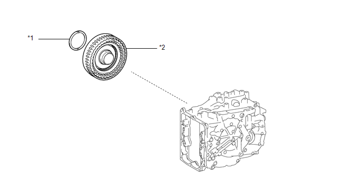
*1 | CLUTCH DRUM OIL SEAL RING |
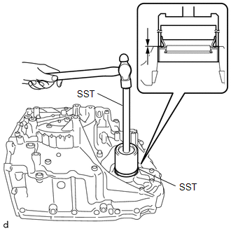
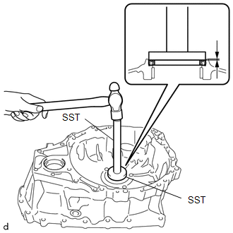
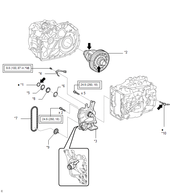
*2 | DIFFERENTIAL CASE ASSEMBLY |
|
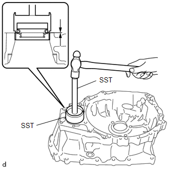
*3 | FRONT OIL PUMP ASSEMBLY |
*4 | MANUAL DETENT SPRING SUB-ASSEMBLY |
|
*5 | OIL PUMP SPROCKET FRONT THRUST WASHER |
*6 | OIL PUMP SPROCKET REAR THRUST WASHER |
|
*7 | TRANSMISSION DRIVE CHAIN |
*8 | TRANSMISSION OIL PUMP DRIVE SPROCKET |
|
*9 | OIL PUMP DRIVE SHAFT SUB-ASSEMBLY |
*10 | NO. 1 BREATHER PLUG (ATM) |
|
|
Tightening torque for "Major areas involving basic vehicle performance such as moving/turning/stopping": N*m (kgf*cm, ft.*lbf) |
● | Non-reusable part |
|
|
Toyota Genuine ATF WS |
 |
MP grease |
ILLUSTRATION
|
*1 | PLANETARY CARRIER THRUST WASHER |
*2 | C-3 AND C-4 CLUTCH ASSEMBLY |
ILLUSTRATION
|
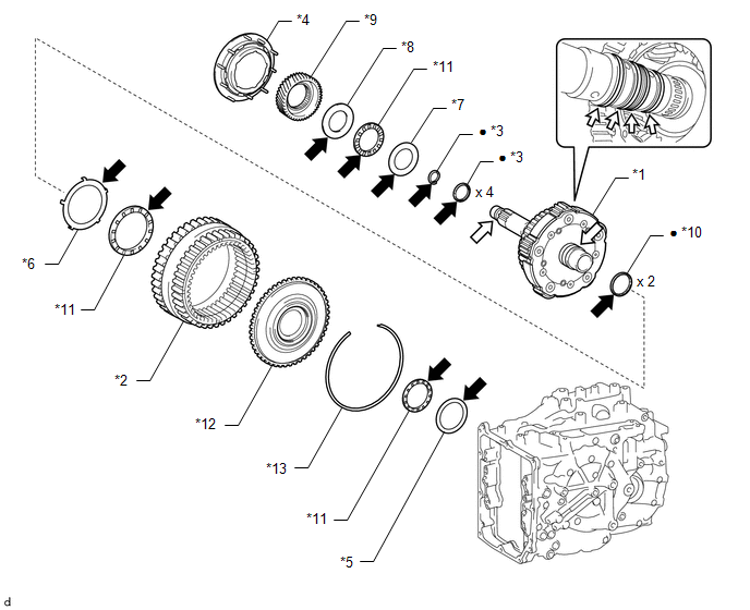
*1 | FRONT PLANETARY GEAR ASSEMBLY |
*2 | FRONT PLANETARY RING GEAR |
|
*3 | INPUT SHAFT OIL SEAL RING |
*4 | NO. 2 PLANETARY CARRIER THRUST WASHER |
|
*5 | NO. 6 THRUST BEARING RACE |
*6 | NO. 7 THRUST BEARING RACE |
|
*7 | NO. 8 THRUST BEARING RACE |
*8 | NO. 9 THRUST BEARING RACE |
|
*9 | PLANETARY SUN GEAR |
*10 | REAR INPUT SHAFT OIL SEAL RING |
|
*11 | THRUST NEEDLE ROLLER BEARING |
*12 | FRONT PLANETARY RING GEAR FLANGE |
|
*13 | SNAP RING |
- | - |
|
● | Non-reusable part |
|
Toyota Genuine ATF WS |
|
|
MP grease | - |
- |
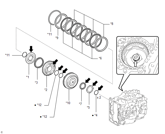
ILLUSTRATION
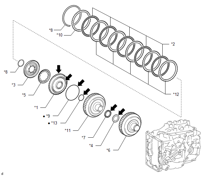
|
*1 | FORWARD CLUTCH PISTON |
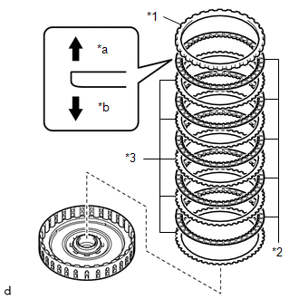
*2 | FRONT CLUTCH CLUTCH DISC |
|
*3 | NO. 1 CLUTCH BALANCER |
*4 | NO. 5 THRUST BEARING RACE |
|
*5 | REAR CLUTCH PISTON RETURN COMPRESSION SPRING |
*6 | SUN GEAR INPUT HUB SUB-ASSEMBLY |
|
*7 | THRUST NEEDLE ROLLER BEARING |
*8 | SNAP RING |
|
*9 | O-RING |
*10 | FORWARD CLUTCH FLANGE |
|
*11 | CLUTCH DRUM SUB-ASSEMBLY |
*12 | FORWARD MULTIPLE DISC CLUTCH CLUTCH PLATE |
|
*13 | D-RING |
- | - |
|
● | Non-reusable part |
|
Toyota Genuine ATF WS |
ILLUSTRATION
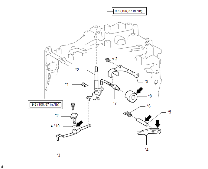
|
*1 | MANUAL VALVE LEVER SHAFT RETAINER SPRING |
*2 | MANUAL VALVE LEVER SHAFT SUB-ASSEMBLY |
|
*3 | MANUAL VALVE LEVER SUB-ASSEMBLY |
*4 | PARKING LOCK PAWL |
|
*5 | PARKING LOCK PAWL SHAFT |
*6 | PARKING LOCK PAWL TORSION SPRING |
|
*7 | PARKING LOCK ROD SUB-ASSEMBLY |
*8 | PARKING LOCK SLEEVE |
|
*9 | PAWL STOPPER PLATE |
*10 | O-RING |
|
|
Tightening torque for "Major areas involving basic vehicle performance such as moving/turning/stopping": N*m (kgf*cm, ft.*lbf) |
● | Non-reusable part |
|
|
Toyota Genuine ATF WS |
- | - |
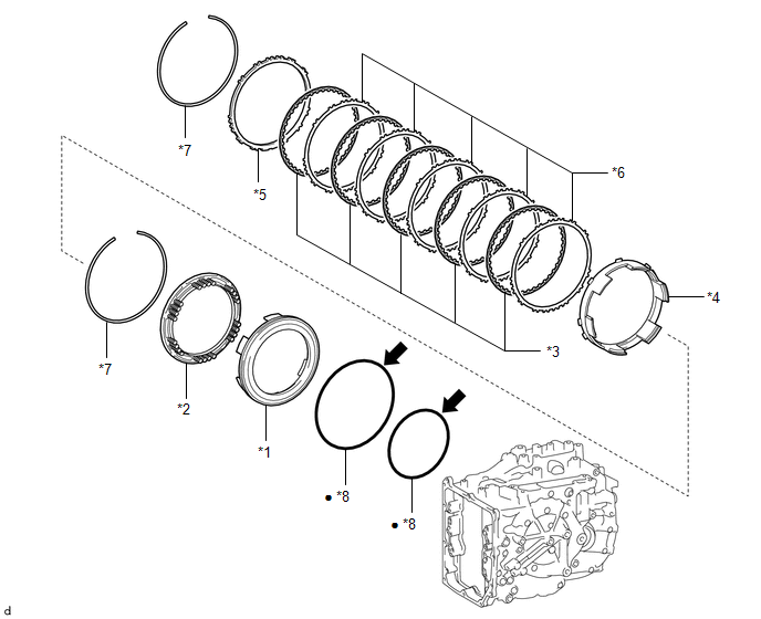
ILLUSTRATION
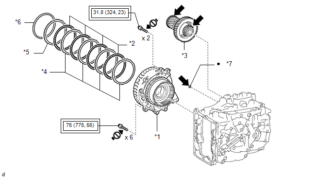
|
*1 | COUNTER DRIVE GEAR SUB-ASSEMBLY |
*2 | NO. 1 BRAKE DISC |
|
*3 | PINION AND COUNTER DRIVEN GEAR SUB-ASSEMBLY |
*4 | NO. 1 BRAKE PLATE |
|
*5 | NO. 1 BRAKE FLANGE |
*6 | SNAP RING |
|
*7 | O-RING |
- | - |
|
|
Tightening torque for "Major areas involving basic vehicle performance such as moving/turning/stopping": N*m (kgf*cm, ft.*lbf) |
● | Non-reusable part |
|
|
Toyota Genuine ATF WS |
 |
Do not apply lubricants to the threaded parts |
ILLUSTRATION
|
*1 | NO. 2 THRUST BEARING RACE |
*2 | NO. 3 PLANETARY CARRIER THRUST WASHER |
|
*3 | NO. 3 THRUST BEARING RACE |
*4 | NO. 4 PLANETARY CARRIER THRUST WASHER |
|
*5 | NO. 4 THRUST BEARING RACE |
*6 | PLANETARY SUN GEAR SUB-ASSEMBLY |
|
*7 | REAR PLANETARY GEAR ASSEMBLY |
*8 | REAR PLANETARY SUN GEAR SUB-ASSEMBLY |
|
*9 | THRUST BEARING RACE |
*10 | THRUST NEEDLE ROLLER BEARING |
|
|
Toyota Genuine ATF WS |
- | - |
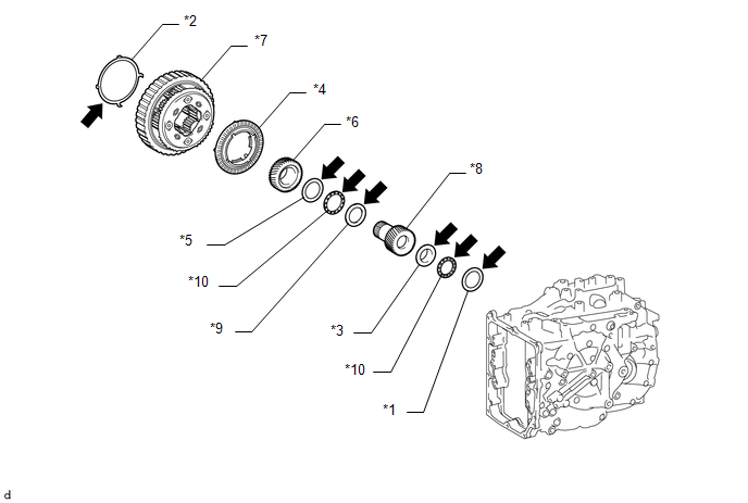
ILLUSTRATION
|
*1 | C-2 CLUTCH BALANCER |
*2 | C-2 CLUTCH PISTON |
|
*3 | CLUTCH RETURN SPRING SUB-ASSEMBLY |
*4 | DIRECT CLUTCH DRUM OIL SEAL RING |
|
*5 | NO. 1 THRUST BEARING RACE |
*6 | NO. 2 CLUTCH DISC |
|
*7 | THRUST NEEDLE ROLLER BEARING |
*8 | NO. 2 CLUTCH PLATE |
|
*9 | DIRECT CLUTCH FLANGE |
*10 | INTERMEDIATE SHAFT SUB-ASSEMBLY |
|
*11 | SNAP RING |
*12 | O-RING |
|
● | Non-reusable part |
|
Toyota Genuine ATF WS |
|
|
MP grease | - |
- |
ILLUSTRATION
|
*1 | 1ST AND REVERSE BRAKE PISTON |
*2 | 1ST AND REVERSE BRAKE RETURN SPRING SUB-ASSEMBLY |
|
*3 | 2ND BRAKE BRAKE DISC |
*4 | NO. 2 1ST AND REVERSE BRAKE PISTON |
|
*5 | 2ND BRAKE BRAKE FLANGE |
*6 | 2ND BRAKE BRAKE PLATE |
|
*7 | SNAP RING |
*8 | O-RING |
|
● | Non-reusable part |
|
Toyota Genuine ATF WS |
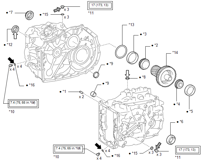
ILLUSTRATION
|
*1 | AUTOMATIC TRANSMISSION CASE STRAIGHT PIN |
*2 | COUNTER DRIVEN GEAR FRONT TAPERED ROLLER BEARING (INNER RACE) |
|
*3 | COUNTER DRIVEN GEAR FRONT TAPERED ROLLER BEARING (OUTER RACE) |
*4 | COUNTER DRIVEN GEAR REAR TAPERED ROLLER BEARING (INNER RACE) |
|
*5 | COUNTER DRIVEN GEAR REAR TAPERED ROLLER BEARING (OUTER RACE) |
*6 | FRONT DRIVE SHAFT OIL SEAL LH |
|
*7 | FRONT DRIVE SHAFT OIL SEAL RH |
*8 | MANUAL VALVE LEVER SHAFT OIL SEAL |
|
*9 | NEEDLE ROLLER BEARING |
*10 | NO. 1 TRANSAXLE CASE PLUG |
|
*11 | NO. 2 TRANSAXLE CASE PLUG |
*12 | TRANSAXLE CASE OIL SEAL |
|
*13 | PINION AND COUNTER DRIVEN GEAR SHIM |
*14 | PINION AND COUNTER DRIVEN GEAR SUB-ASSEMBLY |
|
*15 | GASKET |
*16 | O-RING |
|
|
Tightening torque for "Major areas involving basic vehicle performance such as moving/turning/stopping": N*m (kgf*cm, ft.*lbf) |
● | Non-reusable part |
|
|
Toyota Genuine ATF WS |
|
MP grease |
 |
Toyota Genuine Adhesive 1324, Three Bond 1324 or equivalent |
★ | Precoated part |
DISASSEMBLY
PROCEDURE
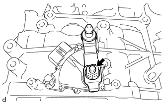
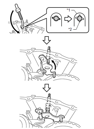
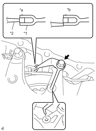
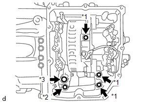
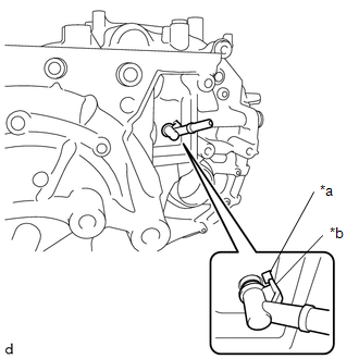
1. REMOVE TRANSMISSION CONTROL SHAFT LEVER
| (a) Remove the nut, washer and transmission control shaft lever from the manual valve lever shaft sub-assembly. |
|
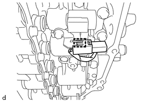
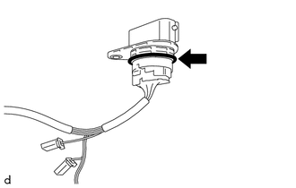
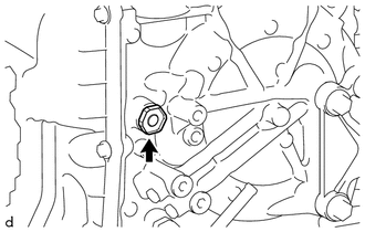
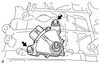
2. REMOVE PARK/NEUTRAL POSITION SWITCH ASSEMBLY
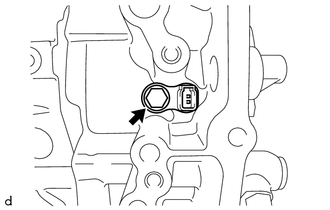
| (a) Remove the 2 bolts and park/neutral position switch assembly from the automatic transaxle case sub-assembly. |
|
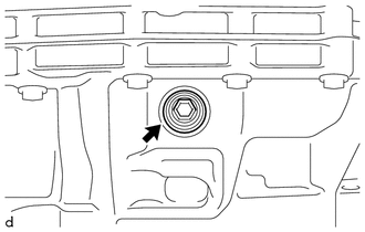
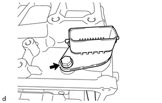
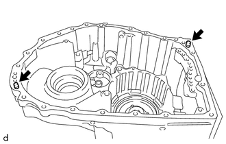
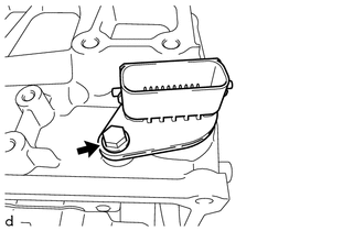
3. REMOVE REFILL PLUG
|
(a) Remove the refill plug and gasket from the automatic transaxle case sub-assembly. |
|
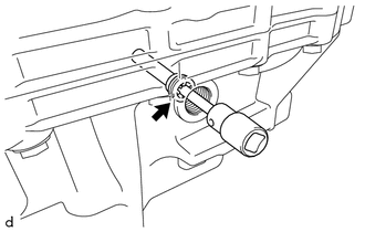
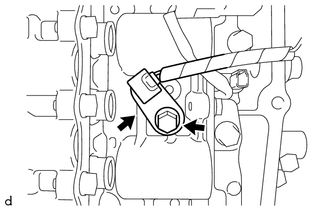
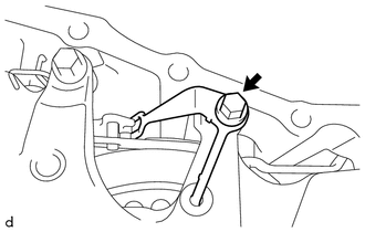
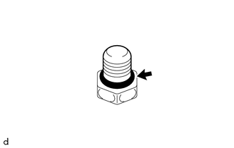
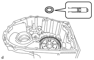
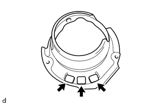
4. REMOVE OVERFLOW PLUG
|
(a) Using a 10 mm socket hexagon wrench, remove the overflow plug and gasket from the transaxle housing. |
|
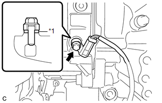
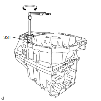
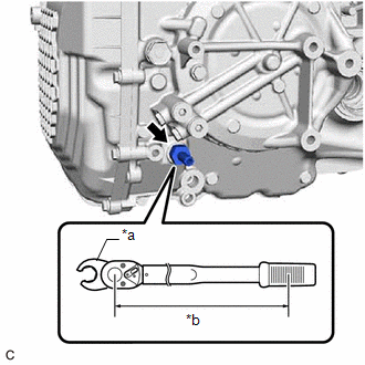
5. REMOVE NO. 1 TRANSMISSION OIL FILLER TUBE
| (a) Using a 6 mm socket hexagon wrench, remove the No. 1 transmission oil filler tube from the transaxle housing. |
|
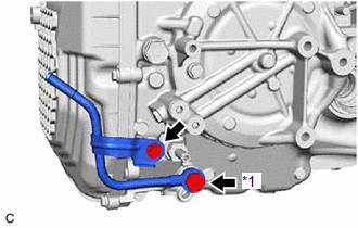
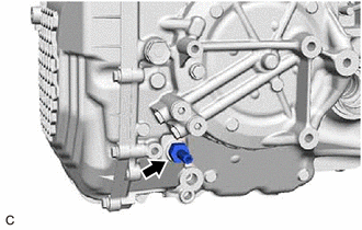
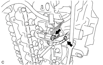
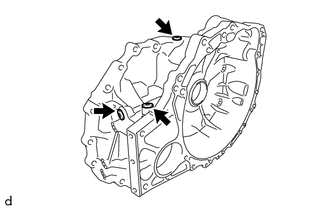
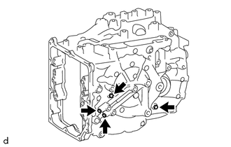
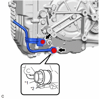
6. REMOVE OIL COOLER UNION SUB-ASSEMBLY
| (a) Remove the bolt to separate the oil cooler union sub-assembly bracket portion from the automatic transaxle case sub-assembly. |
|
(b) Remove the oil cooler union bolt, 2 gaskets and oil cooler union sub-assembly from the automatic transaxle case sub-assembly.
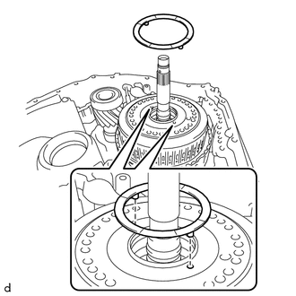
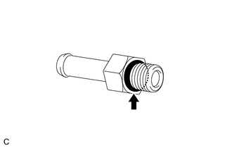
7. REMOVE NO. 1 OIL COOLER OUTLET TUBE SUB-ASSEMBLY
| (a) Using a 19 mm union nut wrench, remove the No. 1 oil cooler outlet tube sub-assembly from the automatic transaxle case sub-assembly. |
|
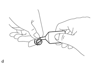
| (b) Remove the O-ring from the No. 1 oil cooler outlet tube sub-assembly. |
|
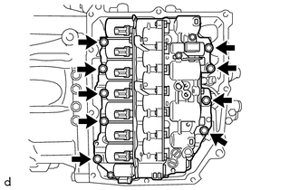
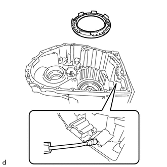
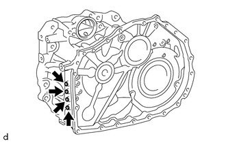
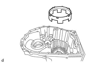
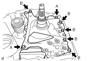
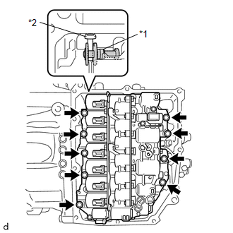
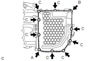
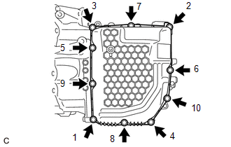
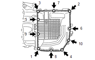
8. REMOVE TRANSMISSION CASE SIDE COVER
| (a) Remove the 10 bolts and transmission case side cover from the automatic transaxle case sub-assembly. |
|
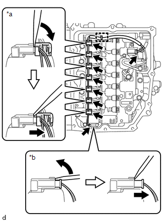
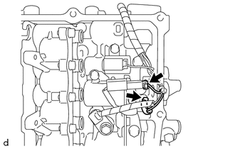
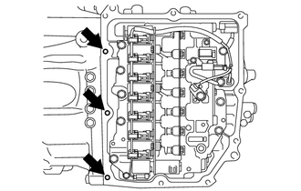
9. REMOVE TRANSMISSION WIRE
| (a) Disengage the clamp to disconnect the transmission wire from the solenoid lock plate. |
|
(b) Disconnect the 9 solenoid valve connectors.
HINT:
| (c) Remove the bolt and temperature sensor clamp and disconnect the temperature sensor from the transmission valve body assembly. |
|
| (d) Disconnect the transmission revolution sensor (NT) connector and transmission revolution sensor (NC) connector. |
|
| (e) Remove the bolt and transmission wire from the automatic transmission case sub-assembly. |
|
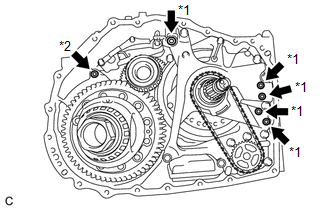
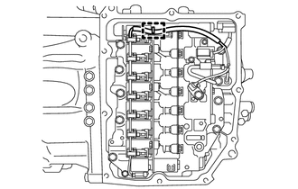
10. REMOVE TRANSMISSION VALVE BODY ASSEMBLY
| (a) Disengage the clamp to disconnect the transmission revolution sensor (NC) wire connector. |
|
| (b) Remove the 9 bolts and transmission valve body assembly from the automatic transaxle case sub-assembly. |
|
| (c) Remove the 2 transaxle case gaskets from the automatic transaxle case sub-assembly. |
|
(d) Remove the transaxle case gasket from the counter drive gear sub-assembly.
(e) Remove the No. 1 front oil pump cover gasket from the front oil pump assembly.
(f) Remove the No. 2 front oil pump cover gasket from the front oil pump assembly.
11. REMOVE TRANSMISSION REVOLUTION SENSOR (NT)
| (a) Remove the bolt and transmission revolution sensor (NT) from the automatic transaxle case sub-assembly. |
|
12. REMOVE TRANSMISSION REVOLUTION SENSOR (NC)
| (a) Remove the bolt, spacer and transmission revolution sensor (NC) from the counter drive gear sub-assembly. |
|
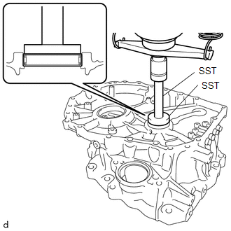
13. INSPECT INPUT SHAFT END PLAY
Click here

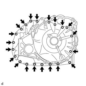
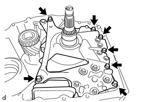
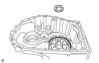
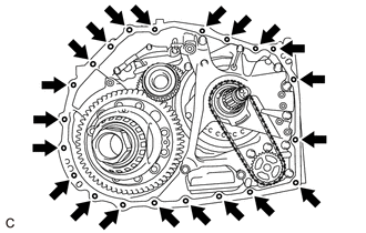
14. REMOVE TRANSAXLE HOUSING
| (a) Remove the 21 bolts. |
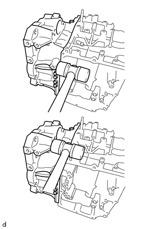
|
| (b) Using a plastic hammer, tap on the circumference of the transaxle housing to remove it from the automatic transaxle case sub-assembly. |
|
| (c) Remove the 5 transaxle case gaskets from the front oil pump assembly. |
|
(d) Remove the O-ring from the automatic transaxle case sub-assembly.
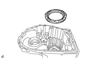
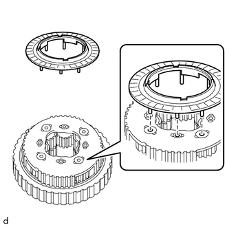
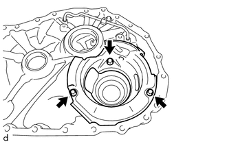
15. REMOVE TRANSAXLE HOUSING OIL SEPARATOR
| (a) Remove the 3 bolts and transaxle housing oil separator from the transaxle housing. |
|
16. REMOVE TRANSMISSION OIL CLEANER MAGNET
| (a) Remove the 3 transmission oil cleaner magnets from the transaxle housing oil separator. |
|
17. INSPECT TRANSMISSION OIL CLEANER MAGNET
Click here
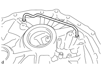
18. REMOVE DIFFERENTIAL GEAR LUBE APPLY TUBE
| (a) Remove the differential gear lube apply tube from the transaxle housing. |
|
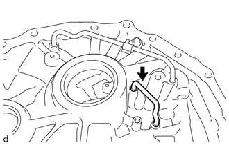
19. REMOVE TRANSMISSION LUBE APPLY TUBE
| (a) Remove the bolt and clamp from the transaxle housing. |
|
| (b) Remove the transmission lube apply tube from the transaxle housing. |
|
20. REMOVE DIFFERENTIAL CASE ASSEMBLY
| (a) Remove the differential case assembly from the automatic transaxle case sub-assembly. |
|
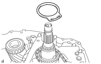
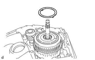
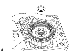
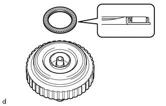
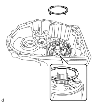
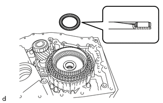
21. REMOVE CLUTCH DRUM OIL SEAL RING
| (a) Remove the clutch drum oil seal ring from the front oil pump assembly. |
|
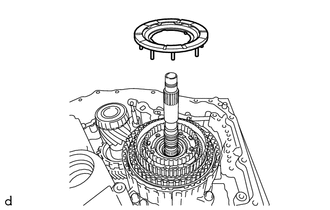
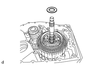
22. REMOVE OIL PUMP SPROCKET FRONT THRUST WASHER
| (a) Remove the oil pump sprocket front thrust washer from the transmission oil pump drive sprocket. |
|
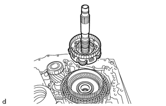
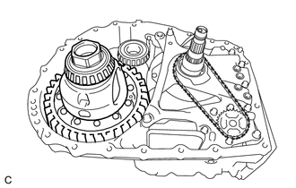
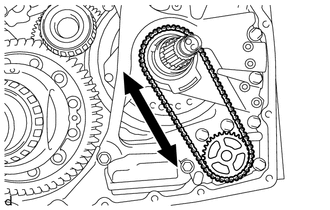
23. REMOVE TRANSMISSION DRIVE CHAIN
| (a) Remove the transmission drive chain together with the transmission oil pump drive sprocket and oil pump drive shaft sub-assembly from the front oil pump assembly. NOTICE: To avoid damaging the bush of the front oil pump assembly, remove the transmission drive chain, transmission oil pump drive sprocket and oil pump drive shaft sub-assembly horizontally relative to the front oil pump assembly. |
|
24. REMOVE OIL PUMP SPROCKET REAR THRUST WASHER
| (a) Remove the oil pump sprocket rear thrust washer from the front oil pump assembly. |
|
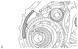
25. REMOVE MANUAL DETENT SPRING SUB-ASSEMBLY
| (a) Remove the bolt and manual detent spring sub-assembly from the front oil pump assembly. |
|
26. REMOVE FRONT OIL PUMP ASSEMBLY
NOTICE:
To avoid damaging the front oil pump assembly and transmission valve body assembly, when removing the front oil pump assembly, first remove the transmission valve body assembly.
| (a) Remove the 7 bolts and front oil pump assembly from the automatic transaxle case sub-assembly. |
|
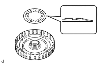
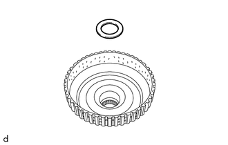
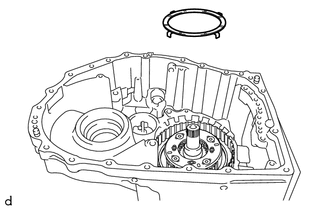
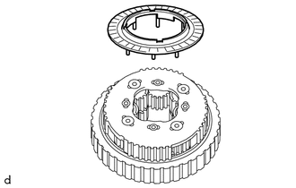
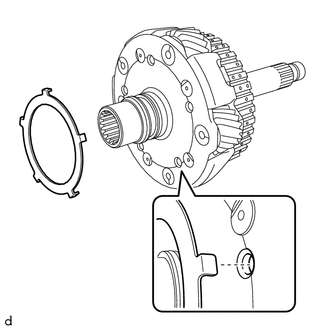
27. REMOVE PLANETARY CARRIER THRUST WASHER
| (a) Remove the planetary carrier thrust washer from the C-3 and C-4 clutch assembly. |
|
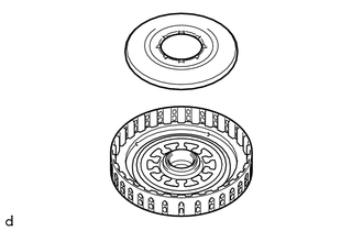
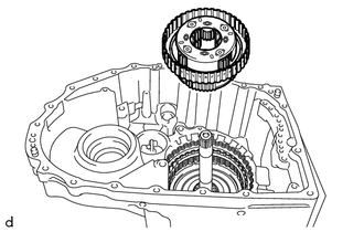
28. REMOVE C-3 AND C-4 CLUTCH ASSEMBLY
| (a) Remove the C-3 and C-4 clutch assembly from the front planetary gear assembly. |
|
29. INSPECT CLEARANCE OF C-3 CLUTCH
Click here
30. INSPECT CLEARANCE OF C-4 CLUTCH
Click here
31. REMOVE NO. 2 PLANETARY CARRIER THRUST WASHER
| (a) Remove the No. 2 planetary carrier thrust washer from the front planetary gear assembly. |
|
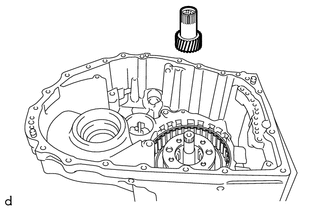
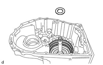
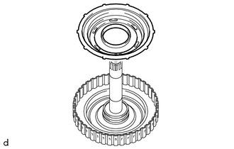
32. REMOVE PLANETARY SUN GEAR
| (a) Remove the planetary sun gear from the front planetary gear assembly. |
|
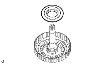
33. REMOVE NO. 9 THRUST BEARING RACE
| (a) Remove the No. 9 thrust bearing race from the front planetary gear assembly. |
|
34. REMOVE THRUST NEEDLE ROLLER BEARING
| (a) Remove the thrust needle roller bearing from the front planetary gear assembly. |
|
35. REMOVE NO. 8 THRUST BEARING RACE
| (a) Remove the No. 8 thrust bearing race from the front planetary gear assembly. |
|
36. REMOVE FRONT PLANETARY GEAR ASSEMBLY
| (a) Remove the front planetary gear assembly from the front planetary ring gear. |
|
37. REMOVE THRUST NEEDLE ROLLER BEARING
| (a) Remove the thrust needle roller bearing from the front planetary ring gear. |
|
38. REMOVE NO. 7 THRUST BEARING RACE
| (a) Remove the No. 7 thrust bearing race from the front planetary gear assembly. |
|
39. INSPECT FRONT PLANETARY GEAR ASSEMBLY
Click here
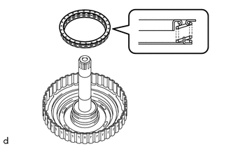
40. REMOVE INPUT SHAFT OIL SEAL RING
| (a) Remove the 5 input shaft oil seal rings from the front planetary gear assembly. |
|
41. REMOVE REAR INPUT SHAFT OIL SEAL RING
| (a) Remove the 2 rear input shaft oil seal rings from the front planetary gear assembly. |
|
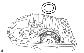
42. REMOVE FRONT PLANETARY RING GEAR
| (a) Remove the front planetary ring gear with front planetary ring gear flange from the C-1 clutch assembly. |
|
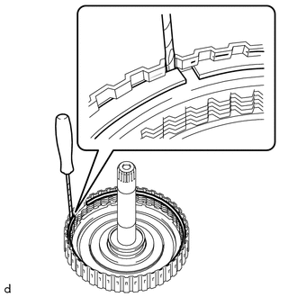
| (b) Using a screwdriver with its tip wrapped with protective tape, remove the snap ring from the front planetary ring gear. NOTICE: Be careful not to damage the front planetary ring gear and front planetary ring gear flange. |
|
| (c) Remove the front planetary ring gear flange from the front planetary ring gear. |
|
43. REMOVE THRUST NEEDLE ROLLER BEARING
| (a) Remove the thrust needle roller bearing from the C-1 clutch assembly. |
|
44. REMOVE NO. 6 THRUST BEARING RACE
| (a) Remove the No. 6 thrust bearing race from the C-1 clutch assembly. |
|
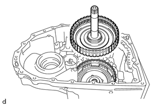
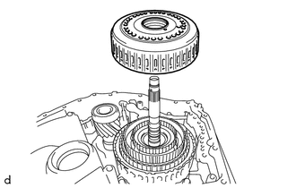
45. REMOVE C-1 CLUTCH ASSEMBLY
| (a) Remove the C-1 clutch assembly from the sun gear input hub sub-assembly. |
|
46. INSPECT CLEARANCE OF C-1 CLUTCH
Click here
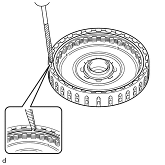
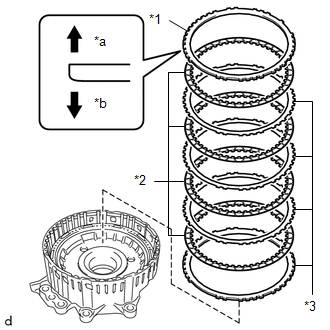
47. REMOVE FRONT CLUTCH CLUTCH DISC
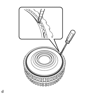
| (a) Using a screwdriver with its tip wrapped in protective tape, remove the snap ring from the clutch drum sub-assembly. NOTICE: Be careful not to damage the clutch drum sub-assembly. |
|
| (b) Remove the forward clutch flange, 5 front clutch clutch discs and 5 forward multiple disc clutch clutch plates from the clutch drum sub-assembly. |
|
48. INSPECT FRONT CLUTCH CLUTCH DISC
Click here
49. REMOVE NO. 1 CLUTCH BALANCER
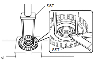
| (a) Place SST on the No. 1 clutch balancer and compress the rear clutch piston return compression spring with a press. SST: 09387-00020 NOTICE: Do not compress the rear clutch piston return compression spring excessively. |
|
(b) Using SST, remove the snap ring from the clutch drum sub-assembly.
SST: 09350-30020
09350-07070
| (c) Remove the No. 1 clutch balancer from the forward clutch piston. |
|
50. REMOVE REAR CLUTCH PISTON RETURN COMPRESSION SPRING
| (a) Remove the rear clutch piston return compression spring from the forward clutch piston. |
|
51. REMOVE FORWARD CLUTCH PISTON
| (a) Apply compressed air (392 kPa (4.0 kgf/cm2, 57 psi)) to the oil hole of the clutch drum sub-assembly to remove the forward clutch piston from the clutch drum sub-assembly. NOTICE:
|
|
| (b) Remove the O-ring from the clutch drum sub-assembly. |
|
| (c) Remove the D-ring from the clutch drum sub-assembly. |
|
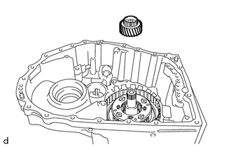
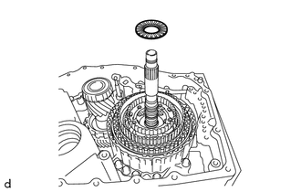
52. REMOVE SUN GEAR INPUT HUB SUB-ASSEMBLY
| (a) Remove the sun gear input hub sub-assembly from the counter drive gear sub-assembly. |
|
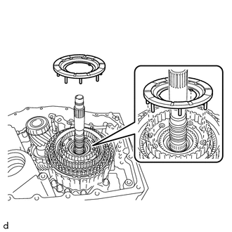
53. REMOVE THRUST NEEDLE ROLLER BEARING
| (a) Remove the thrust needle roller bearing from the sun gear input hub sub-assembly. |
|
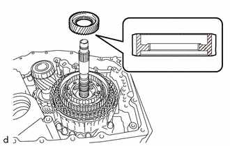
54. REMOVE NO. 5 THRUST BEARING RACE
| (a) Remove the No. 5 thrust bearing race from the sun gear input hub sub-assembly. |
|
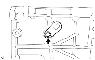
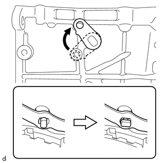
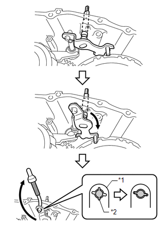
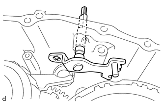
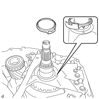
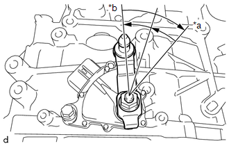
55. REMOVE MANUAL VALVE LEVER SHAFT SUB-ASSEMBLY
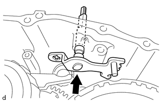
| (a) Remove the bolt. |
|
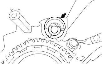
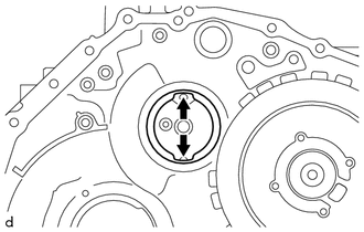
| (b) Align the cutouts of the manual valve lever sub-assembly and manual valve lever shaft sub-assembly, and remove the manual valve lever shaft sub-assembly. HINT: Rotating the manual valve lever shaft sub-assembly to the area shown in the illustration will align the cutouts. |
|
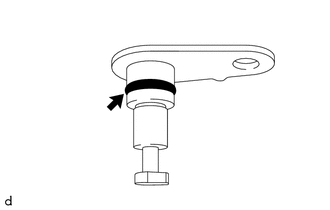
| (c) Remove the O-ring from the manual valve lever shaft sub-assembly. |
|
56. REMOVE MANUAL VALVE LEVER SUB-ASSEMBLY
| (a) Remove the manual valve lever sub-assembly from the automatic transaxle case sub-assembly. |
|
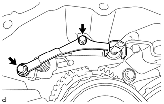
57. REMOVE PAWL STOPPER PLATE
| (a) Remove the 2 bolts and pawl stopper plate from the automatic transaxle case sub-assembly. |
|
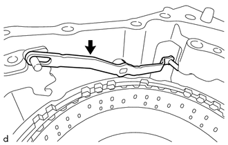
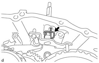
58. REMOVE MANUAL VALVE LEVER SHAFT RETAINER SPRING
| (a) Remove the manual valve lever shaft retainer spring from the automatic transaxle case sub-assembly. |
|
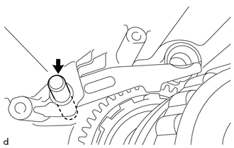
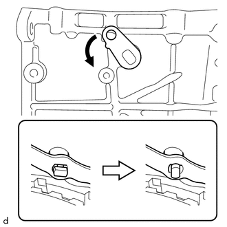
59. REMOVE PARKING LOCK ROD SUB-ASSEMBLY
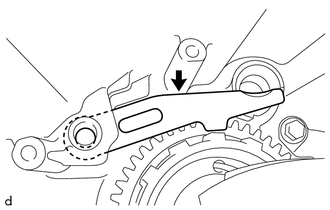
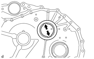
| (a) Move the manual valve lever shaft sub-assembly and parking lock rod sub-assembly as shown in the illustration, and remove the parking lock rod sub-assembly. HINT: Align the cutouts of the parking lock rod sub-assembly and manual valve lever shaft sub-assembly and remove the parking lock rod sub-assembly. |
|
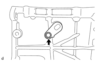
60. REMOVE MANUAL VALVE LEVER SHAFT SUB-ASSEMBLY
| (a) Remove the manual valve lever shaft sub-assembly from the automatic transaxle case sub-assembly. |
|
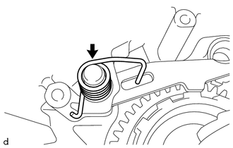
61. REMOVE PARKING LOCK PAWL TORSION SPRING
| (a) Remove the parking lock pawl torsion spring from the automatic transaxle case sub-assembly. |
|
62. REMOVE PARKING LOCK PAWL SHAFT
| (a) Remove the parking lock pawl shaft from the automatic transaxle case sub-assembly. |
|
63. REMOVE PARKING LOCK PAWL
| (a) Remove the parking lock pawl from the automatic transaxle case sub-assembly. |
|
64. REMOVE PARKING LOCK SLEEVE
| (a) Remove the parking lock sleeve from the automatic transaxle case sub-assembly. |
|
65. INSPECT CLEARANCE OF B-1 BRAKE
Click here
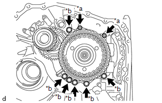
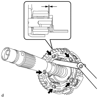
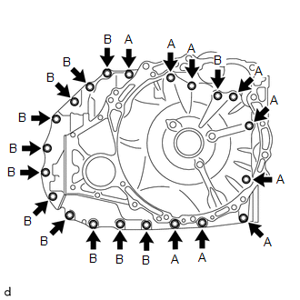
66. REMOVE COUNTER DRIVE GEAR SUB-ASSEMBLY
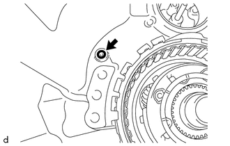
| (a) Using a T50 "TORX" socket wrench, remove the 2 bolts (A) from the counter drive gear sub-assembly. |
|
(b) Remove the 6 bolts (B) from the counter drive gear sub-assembly.
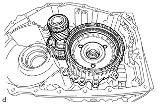
| (c) Remove the counter drive gear sub-assembly together with the pinion and counter driven gear sub-assembly from the automatic transaxle case sub-assembly. |
|
| (d) Remove the O-ring from the automatic transaxle case sub-assembly. |
|
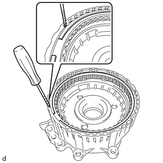
67. REMOVE NO. 1 BRAKE DISC
| (a) Using a screwdriver with its tip wrapped in protective tape, remove the snap ring from the counter drive gear sub-assembly. NOTICE: Be careful not to damage the counter drive gear sub-assembly. |
|
| (b) Remove the No. 1 brake flange, 4 No. 1 brake discs and 4 No. 1 brake plates from the counter drive gear sub-assembly. |
|
68. INSPECT NO. 1 BRAKE DISC
Click here
69. REMOVE NO. 3 PLANETARY CARRIER THRUST WASHER
| (a) Remove the No. 3 planetary carrier thrust washer from the rear planetary gear assembly. |
|
70. REMOVE PLANETARY SUN GEAR SUB-ASSEMBLY
| (a) Remove the planetary sun gear sub-assembly from the rear planetary gear assembly. |
|
71. INSPECT PLANETARY SUN GEAR SUB-ASSEMBLY
Click here
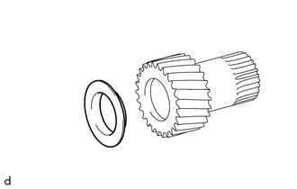
72. REMOVE REAR PLANETARY SUN GEAR SUB-ASSEMBLY
| (a) Remove the rear planetary sun gear sub-assembly from the C-2 clutch assembly. |
|
73. REMOVE REAR PLANETARY GEAR ASSEMBLY
| (a) Remove the rear planetary gear assembly from the C-2 clutch assembly. |
|
74. REMOVE NO. 4 PLANETARY CARRIER THRUST WASHER
| (a) Remove the No. 4 planetary carrier thrust washer from the rear planetary gear assembly. |
|
75. INSPECT REAR PLANETARY GEAR ASSEMBLY
Click here
76. REMOVE NO. 4 THRUST BEARING RACE
| (a) Remove the No. 4 thrust bearing race from the rear planetary sun gear sub-assembly. |
|
77. REMOVE THRUST NEEDLE ROLLER BEARING
| (a) Remove the thrust needle roller bearing from the rear planetary sun gear sub-assembly. |
|
78. REMOVE THRUST BEARING RACE
| (a) Remove the thrust bearing race from the rear planetary sun gear sub-assembly. |
|
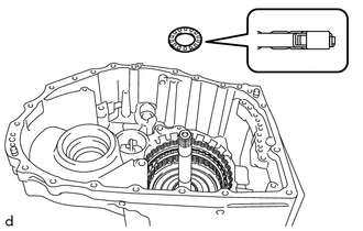
79. REMOVE NO. 3 THRUST BEARING RACE
| (a) Remove the No. 3 thrust bearing race from the rear planetary sun gear sub-assembly. |
|
80. INSPECT REAR PLANETARY SUN GEAR SUB-ASSEMBLY
Click here
81. REMOVE THRUST NEEDLE ROLLER BEARING
| (a) Remove the thrust needle roller bearing from the C-2 clutch assembly. |
|
82. REMOVE NO. 2 THRUST BEARING RACE
| (a) Remove the No. 2 thrust bearing race from the C-2 clutch assembly. |
|
83. INSPECT CLEARANCE OF C-2 CLUTCH
Click here
84. REMOVE C-2 CLUTCH ASSEMBLY
| (a) Remove the C-2 clutch assembly from the automatic transaxle case sub-assembly. |
|
85. REMOVE THRUST NEEDLE ROLLER BEARING
| (a) Remove the thrust needle roller bearing from the C-2 clutch assembly. |
|
86. REMOVE NO. 1 THRUST BEARING RACE
| (a) Remove the No. 1 thrust bearing race from the automatic transaxle case sub-assembly. |
|
87. REMOVE NO. 2 CLUTCH DISC
| (a) Using a screwdriver with its tip wrapped in protective tape, remove the snap ring from the intermediate shaft sub-assembly. NOTICE: Be careful not to damage the intermediate shaft sub-assembly. |
|
| (b) Remove the direct clutch flange, 4 No. 2 clutch discs and 4 No. 2 clutch plates from the intermediate shaft sub-assembly. |
|
88. INSPECT NO. 2 CLUTCH DISC
Click here
89. REMOVE C-2 CLUTCH BALANCER
| (a) Place SST on the C-2 clutch balancer and compress the clutch return spring sub-assembly with a press. SST: 09387-00020 NOTICE: Do not compress the clutch return spring sub-assembly excessively. |
|
(b) Using SST, remove the snap ring from the intermediate shaft sub-assembly.
SST: 09350-30020
09350-07070
| (c) Remove the C-2 clutch balancer from the intermediate shaft sub-assembly. |
|
90. REMOVE CLUTCH RETURN SPRING SUB-ASSEMBLY
| (a) Remove the clutch return spring sub-assembly from the intermediate shaft sub-assembly. |
|
91. INSPECT CLUTCH RETURN SPRING SUB-ASSEMBLY
Click here
92. REMOVE C-2 CLUTCH PISTON
| (a) Apply compressed air (392 kPa (4.0 kgf/cm2, 57 psi)) to the oil hole of the intermediate shaft sub-assembly. NOTICE:
|
|
| (b) Remove the C-2 clutch piston from the intermediate shaft sub-assembly. |
|
| (c) Remove the 2 O-rings from the intermediate shaft sub-assembly. |
|
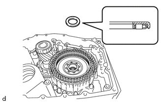
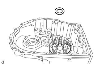
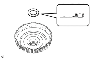
93. REMOVE DIRECT CLUTCH DRUM OIL SEAL RING
| (a) Remove the 2 direct clutch drum oil seal rings from the automatic transaxle case sub-assembly. |
|
94. INSPECT CLEARANCE OF B-2 BRAKE
Click here
95. REMOVE 2ND BRAKE BRAKE DISC
| (a) Using a screwdriver with its tip wrapped with protective tape, remove the snap ring from the automatic transaxle case sub-assembly. NOTICE: Be careful not to damage the automatic transaxle case sub-assembly. |
|
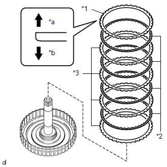
| (b) Remove the 2nd brake brake flange, 5 2nd brake brake discs and 5 2nd brake brake plates from the automatic transaxle case sub-assembly. |
|
96. INSPECT 2ND BRAKE BRAKE DISC
Click here
97. REMOVE NO. 2 1ST AND REVERSE BRAKE PISTON
| (a) Remove the No. 2 1st and reverse brake piston from the automatic transaxle case sub-assembly. |
|
98. REMOVE 1ST AND REVERSE BRAKE RETURN SPRING SUB-ASSEMBLY
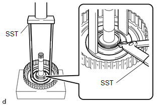
| (a) Place SST on the 1st and reverse brake return spring sub-assembly and compress it with a press. SST: 09380-60011 09381-06020 09381-06050 09381-06060 09381-06100 09381-06110 SST: 09950-70010 09951-07200 NOTICE: Do not compress the 1st and reverse brake return spring sub-assembly excessively. |
|
| (b) Using a screwdriver with its tip wrapped with protective tape, remove the snap ring from the automatic transaxle case sub-assembly. NOTICE: Be careful not to damage the automatic transaxle case sub-assembly. |
|
| (c) Remove the 1st and reverse brake return spring sub-assembly from the automatic transaxle case sub-assembly. |
|
99. INSPECT 1ST AND REVERSE BRAKE RETURN SPRING SUB-ASSEMBLY
Click here
100. REMOVE 1ST AND REVERSE BRAKE PISTON
| (a) Apply compressed air (approximately 392 kPa (4.0 kgf/cm2, 57 psi)) to the ATF hole to remove the 1st and reverse brake piston from the automatic transaxle case sub-assembly. |
|
| (b) Remove the 2 O-rings from the 1st and reverse brake piston. |
|
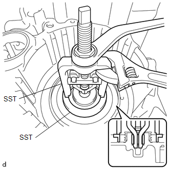
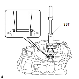
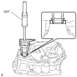
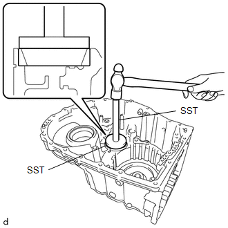
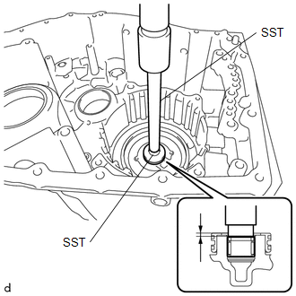
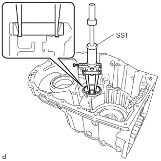
101. REMOVE NEEDLE ROLLER BEARING
| (a) Using SST, remove the needle roller bearing from the automatic transaxle case sub-assembly. SST: 09303-55010 SST: 09502-12010 NOTICE: Be careful not to damage the automatic transaxle case sub-assembly. |
|
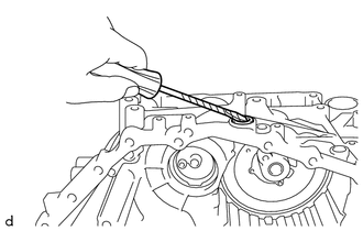
102. REMOVE MANUAL VALVE LEVER SHAFT OIL SEAL
| (a) Using a screwdriver with its tip wrapped with protective tape, remove the manual valve lever shaft oil seal from the automatic transaxle case sub-assembly. NOTICE: Be careful not to damage the automatic transaxle case sub-assembly. |
|
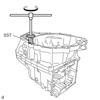
103. REMOVE TRANSAXLE CASE OIL SEAL
| (a) Using SST, remove the transaxle case oil seal from the transaxle housing. SST: 09308-36010 NOTICE: Be careful not to damage the transaxle housing. |
|
104. REMOVE FRONT DRIVE SHAFT OIL SEAL RH
| (a) Using SST, remove the front drive shaft oil seal RH from the transaxle housing. SST: 09308-36010 NOTICE: Be careful not to damage the transaxle housing. |
|
105. REMOVE FRONT DRIVE SHAFT OIL SEAL LH
| (a) Using SST, remove the front drive shaft oil seal LH from the automatic transaxle case sub-assembly. SST: 09308-36010 NOTICE: Be careful not to damage the automatic transaxle case sub-assembly. |
|
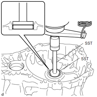
106. REMOVE NEEDLE ROLLER BEARING
| (a) Using SST and a press, remove the needle roller bearing from the transaxle housing. SST: 09950-60011 09951-00550 SST: 09950-70010 09951-07200 NOTICE: Be careful not to damage the transaxle housing. |
|
107. REMOVE COUNTER DRIVEN GEAR REAR TAPERED ROLLER BEARING (OUTER RACE)
(a) Using SST, remove the counter driven gear rear tapered roller bearing (outer race) from the automatic transaxle case sub-assembly.
SST: 09308-36010
NOTICE:
Be careful not to damage the automatic transaxle case sub-assembly.
HINT:
Align the claw of the SST with the indentation of the automatic transaxle case sub-assembly when removing the parts.
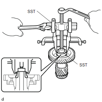
108. REMOVE COUNTER DRIVEN GEAR REAR TAPERED ROLLER BEARING (INNER RACE)
| (a) Using SST, remove the counter driven gear rear tapered roller bearing (inner race) from the pinion and counter driven gear sub-assembly. SST: 09950-40011 09951-04010 09952-04010 09953-04030 09954-04010 09955-04011 09957-04010 09958-04011 SST: 09950-60011 09951-00310 NOTICE: Because SST is attached to the roller portion, there is a possibility that the roller portion could break and SST could come off before the counter driven gear tapered roller bearing (rear side inner race) comes off. |
|
| (b) If the roller portion breaks and SST comes off, reattach SST to the inner race in the position shown in the illustration, and continue removing the parts. SST: 09950-40011 09951-04010 09952-04010 09953-04030 09954-04010 09955-04011 09957-04010 09958-04011 SST: 09950-60011 09951-00310 |
|
109. REMOVE COUNTER DRIVEN GEAR FRONT TAPERED ROLLER BEARING (OUTER RACE)
(a) Using SST, remove the counter driven gear front tapered roller bearing (outer race) and pinion and counter driven gear shim from the transaxle housing.
SST: 09308-36010
NOTICE:
Be careful not to damage the transaxle housing.
HINT:
Align the claw of the SST with the indentation of the transaxle housing when removing the parts.
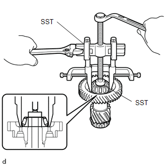
110. REMOVE COUNTER DRIVEN GEAR FRONT TAPERED ROLLER BEARING (INNER RACE)
| (a) Using SST, remove the counter driven gear front tapered roller bearing (inner race) from the pinion and counter driven gear sub-assembly. SST: 09950-00020 SST: 09950-00030 SST: 09950-60011 09951-00380 |
|
111. REMOVE NO. 1 TRANSAXLE CASE PLUG
| (a) Remove the 4 No. 1 transaxle case plugs from the automatic transaxle case sub-assembly. |
|
| (b) Remove the 4 No. 1 transaxle case plugs from the transaxle housing. |
|
| (c) Remove the 8 O-rings from the 8 No. 1 transaxle case plugs. |
|
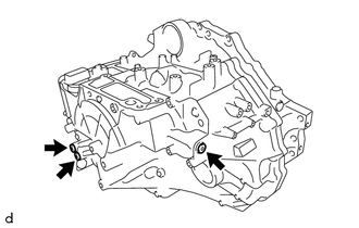
112. REMOVE NO. 2 TRANSAXLE CASE PLUG
| (a) Using a 6 mm socket hexagon wrench, remove the 3 No. 2 transaxle case plugs and 3 gaskets from the automatic transaxle case sub-assembly. |
|
| (b) Using a 6 mm socket hexagon wrench, remove the 3 No. 2 transaxle case plugs and 3 gaskets from the transaxle housing. |
|
113. REMOVE AUTOMATIC TRANSMISSION CASE STRAIGHT PIN
NOTICE:
It is not necessary to remove the automatic transmission case straight pins unless they are being replaced.
| (a) Remove the 2 automatic transmission case straight pins from the automatic transaxle case sub-assembly. |
|
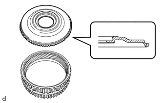
114. REMOVE NO. 1 BREATHER PLUG (ATM)
| (a) Disengage each claw and remove the No. 1 breather plug (ATM) from the automatic transaxle case sub-assembly. NOTICE: Be careful not to damage the automatic transaxle case sub-assembly. |
|
INSPECTION
PROCEDURE
1. INSPECT TRANSMISSION OIL CLEANER MAGNET
| (a) Use the removed transmission oil cleaner magnets to collect any steel chips. Examine the chips and particles in the transaxle housing and on the transmission oil cleaner magnets to determine what type of wear might be found in the automatic transaxle assembly. Result: Steel (magnetic) Bearing, gear and plate wear Brass (non-magnetic) Bushing wear |
|
2. INSPECT FRONT CLUTCH CLUTCH DISC
| (a) Check if the contact surfaces of the front clutch clutch disc, forward multiple disc clutch clutch plate and forward clutch flange are worn or burnt. If necessary, replace them. NOTICE:
|
|
3. INSPECT NO. 2 CLUTCH DISC
| (a) Check if the contact surfaces of the No. 2 clutch disc, No. 2 clutch plate and direct clutch flange are worn or burnt. If necessary, replace them. NOTICE:
|
|
4. INSPECT NO. 1 BRAKE DISC
| (a) Check if the contact surfaces of the No. 1 brake disc, No. 1 brake plate and No. 1 brake flange are worn or burnt. If necessary, replace them. NOTICE:
|
|
5. INSPECT 2ND BRAKE BRAKE DISC
| (a) Check if the contact surfaces of the 2nd brake brake disc, 2nd brake brake plate and 2nd brake brake flange are worn or burnt. If necessary, replace them. NOTICE:
|
|
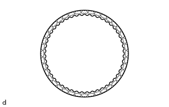
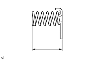
6. INSPECT CLUTCH RETURN SPRING SUB-ASSEMBLY
| (a) Using a vernier caliper, measure the free length of the clutch return spring sub-assembly together with the spring seat. Standard Free Length: 14.61 mm (0.575 in.) If the free length is shorter than the standard free length, replace the clutch return spring sub-assembly. |
|
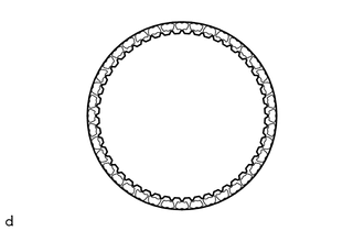
7. INSPECT 1ST AND REVERSE BRAKE RETURN SPRING SUB-ASSEMBLY
| (a) Using a vernier caliper, measure the free length of the 1st and reverse brake return spring sub-assembly together with the spring seat. Standard Free Length: 18.29 mm (0.720 in.) If the free length is shorter than the standard free length, replace the 1st and reverse brake return spring sub-assembly. |
|
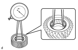
8. INSPECT PLANETARY SUN GEAR SUB-ASSEMBLY
| (a) Using a caliper gauge, measure the inside diameter of the bushing of the planetary sun gear sub-assembly. Standard Inside Diameter: 33.286 to 33.312 mm (1.310 to 1.311 in.) Maximum Inside Diameter: 33.312 mm (1.311 in.) If the inside diameter is more than the maximum, replace the planetary sun gear sub-assembly. |
|
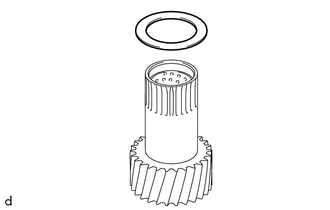
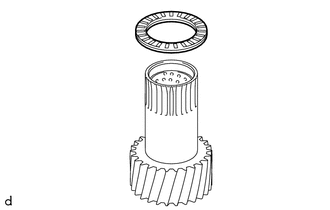
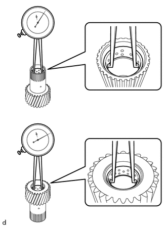
9. INSPECT REAR PLANETARY SUN GEAR SUB-ASSEMBLY
| (a) Using a caliper gauge, measure the inside diameter of the bushing of the rear planetary sun gear sub-assembly. Standard Inside Diameter: 24.287 to 24.313 mm (0.956 to 0.957 in.) Maximum Inside Diameter: 24.313 mm (0.957 in.) If the inside diameter is more than the maximum, replace the rear planetary sun gear sub-assembly. |
|
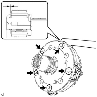
10. INSPECT FRONT PLANETARY GEAR ASSEMBLY
| (a) for Outer Pinion: (1) Using a feeler gauge, measure the clearance between the planetary carrier and pinion gears at 5 points. Standard Clearance: 0.2 to 0.6 mm (0.00787 to 0.0236 in.) If the clearance is more than the standard clearance, replace the front planetary gear assembly. |
|
| (b) for Inner Pinion: (1) Using a feeler gauge, measure the clearance between the planetary carrier and pinion gears at 5 points. Standard Clearance: 0.2 to 0.6 mm (0.00787 to 0.0236 in.) If the clearance is more than the standard clearance, replace the front planetary gear assembly. |
|
11. INSPECT REAR PLANETARY GEAR ASSEMBLY
| (a) for Long Pinion: (1) Using a feeler gauge, measure the clearance between the planetary carrier and pinion gears at 4 points. Standard Clearance: 0.15 to 1.05 mm (0.00591 to 0.0413 in.) If the clearance is more than the standard clearance, replace the rear planetary gear assembly. |
|
| (b) for Short Pinion: (1) Using a feeler gauge, measure the clearance between the planetary carrier and pinion gears at 4 points. Standard Clearance: 0.15 to 0.85 mm (0.00591 to 0.0335 in.) If the clearance is more than the standard clearance, replace the rear planetary gear assembly. |
|
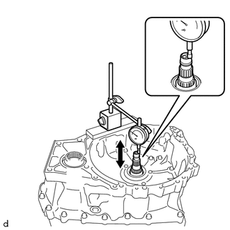
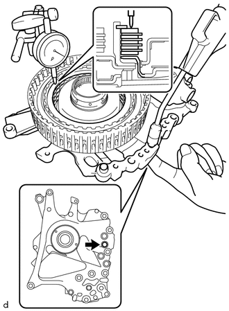
12. INSPECT INPUT SHAFT END PLAY
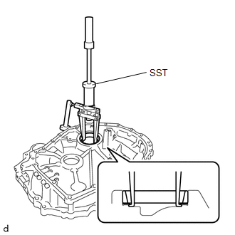
| (a) Using a dial indicator, measure the input shaft end play. Standard Input Shaft End Play: 0.332 to 1.103 mm (0.0131 to 0.0434 in.) |
|
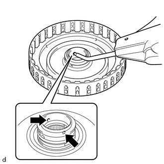
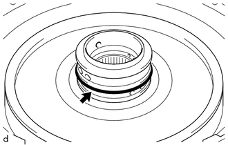
13. INSPECT CLEARANCE OF C-3 CLUTCH
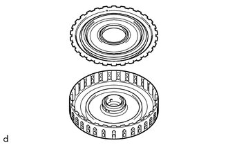
(a) Set the C-3 and C-4 clutch assembly on the front oil pump assembly.
(b) Using a dial indicator, measure the clearance of the C-3 clutch while applying compressed air (approximately 200 kPa (2.0 kgf/cm2, 29 psi)).
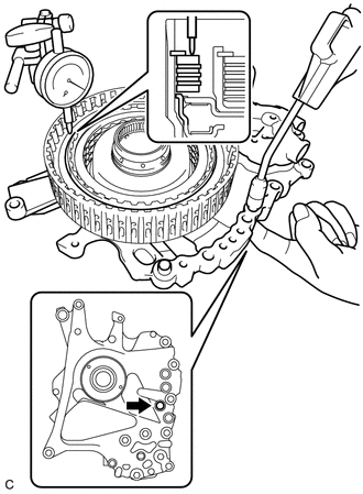
 | Cover Oil Hole |
Pack Clearance (Reference):
0.19 to 0.61 mm (0.00748 to 0.0240 in.)
HINT:
If the clearance is not as specified, replace the C-3 and C-4 clutch assembly.
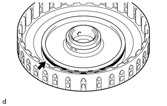
14. INSPECT CLEARANCE OF C-4 CLUTCH
(a) Set the C-3 and C-4 clutch assembly on the front oil pump assembly.
(b) Using a dial indicator, measure the clearance of the C-4 clutch while applying compressed air (approximately 400 kPa (4.1 kgf/cm2, 58 psi)).
|
| Cover Oil Hole |
Pack Clearance (Reference):
0.27 to 0.73 mm (0.0106 to 0.0287 in.)
HINT:
If the clearance is not as specified, replace the C-3 and C-4 clutch assembly.
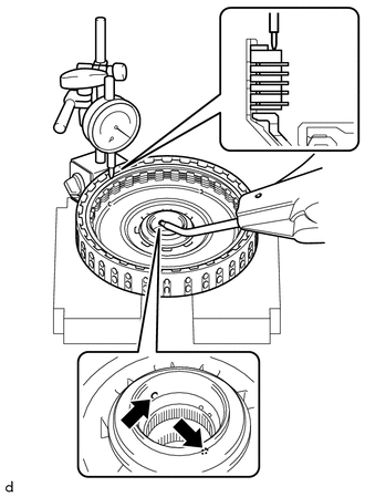
15. INSPECT CLEARANCE OF C-1 CLUTCH
HINT:
TMC Made and TMMWV Made components can be identified by the location where the serial number is stamped.
|
*a | TMC Made |
|
*b | TMMWV Made |
| (a) Using a dial indicator, measure the clearance of the C-1 clutch while applying compressed air (approximately 200 kPa (2.0 kgf/cm2, 29 psi)). Pack Clearance (Reference): 1.0 to 1.2 mm (0.0394 to 0.0472 in.) HINT:
If the clearance is not as specified, select an appropriate forward clutch flange so that the clearance will be within the specified range. Forward Clutch Flange Thickness: for TMC Made:
|
|
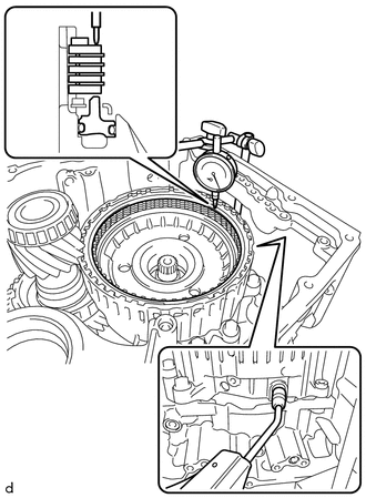
16. INSPECT CLEARANCE OF B-1 BRAKE
HINT:
TMC Made and TMMWV Made components can be identified by the location where the serial number is stamped.
|
*a | TMC Made |
|
*b | TMMWV Made |
| (a) Using a dial indicator, measure the clearance of the B-1 brake while applying compressed air (approximately 200 kPa (2.0 kgf/cm2, 29 psi)). Pack Clearance: 0.8 to 1.0 mm (0.0315 to 0.0394 in.) HINT: To find the clearance, measure in at least 3 locations and average the results. If the clearance is not as specified, select an appropriate No. 1 brake flange so that the clearance will be within the specified range. No. 1 Brake Flange Thickness: for TMC Made:
|
|
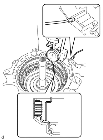
17. INSPECT CLEARANCE OF C-2 CLUTCH
HINT:
TMC Made and TMMWV Made components can be identified by the location where the serial number is stamped.
|
*a | TMC Made |
|
*b | TMMWV Made |
| (a) Using a dial indicator, measure the clearance of the C-2 clutch while applying compressed air (approximately 400 kPa (4.1 kgf/cm2, 58 psi)). Piston Stroke: 0.8 to 1.0 mm (0.0315 to 0.0394 in.) HINT: To find the clearance, measure in at least 3 locations and average the results. If the clearance is not as specified, select an appropriate direct clutch flange so that the clearance will be within the specified range. Direct Clutch Flange Thickness: for TMC Made:
|
|
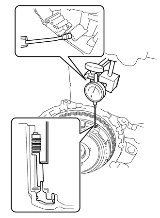
18. INSPECT CLEARANCE OF B-2 BRAKE
HINT:
TMC Made and TMMWV Made components can be identified by the location where the serial number is stamped.
|
*a | TMC Made |
|
*b | TMMWV Made |
| (a) Using a dial indicator, measure the clearance of the B-2 brake while applying compressed air (approximately 200 kPa (2.0 kgf/cm2, 29 psi)). Piston Stroke: 1.0 to 1.2 mm (0.0394 to 0.0472 in.) HINT: To find the clearance, measure in at least 3 locations and average the results. If the clearance is not as specified, select an appropriate 2nd brake brake flange so that the clearance will be within the specified range. HINT: There are 7 2nd brake brake flanges of different thicknesses available. 2nd Brake Brake Flange Thickness: for TMC Made:
|
|
REASSEMBLY
PROCEDURE
1. BEARING POSITION
Check bearing position and installation direction.
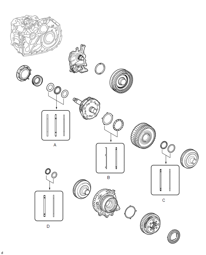
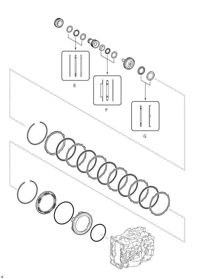
Thrust Needle Roller Bearing and Bearing Race Diameter:
|
Mark | Front Side Thrust Bearing Race Diameter Inside / Outside mm (in.) | Thrust Bearing Diameter Inside / Outside mm (in.) | Rear Side Thrust Bearing Race Diameter Inside / Outside mm (in.) |
|---|---|---|---|
| A |
32.6 (1.28) / 54.2 (2.13) |
31.7 (1.25) / 52.3 (2.06) |
31.7 (1.25) / 52.3 (2.06) |
|
B | 59.8 (2.35) / 77.0 (3.03) |
58.3 (2.30) / 75.0 (2.95) |
- |
| C |
- | 39.2 (1.54) / 52.6 (2.07) |
38.1 (1.50) / 50.2 (1.98) |
|
D | - |
33.3 (1.31) / 46.3 (1.82) |
34.2 (1.35) / 47.3 (1.86) |
|
E | 34.4 (1.35) / 48.7 (1.92) |
33.2 (1.31) / 47.7 (1.88) |
33.2 (1.31) / 47.7 (1.88) |
|
F | 25.58 (1.01) / 43.7 (1.72) |
24.2 (0.953) / 43.7 (1.72) |
24.2 (0.953) / 43.7 (1.72) |
|
G | - |
50.5 (1.99) / 74.5 (2.93) |
52.8 (2.08) / 76.4 (3.01) |
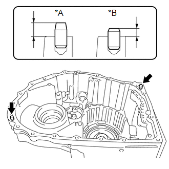
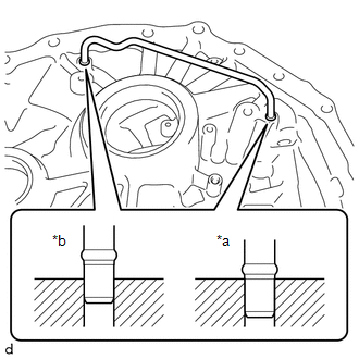
2. INSTALL AUTOMATIC TRANSMISSION CASE STRAIGHT PIN
NOTICE:
It is not necessary to remove the automatic transmission case straight pins unless they are being replaced.
HINT:
TMC Made and TMMWV Made components can be identified by the location where the serial number is stamped.

|
*a | TMC Made |
|
*b | TMMWV Made |
| (a) Using a plastic hammer, tap in 2 new automatic transmission case straight pins to the specified protrusion height. Protrusion Height: for TMC Made 10.7 to 11.3 mm (0.421 to 0.445 in.) for TMMWV Made 7.0 to 8.0 mm (0.276 to 0.315 in.) |
|
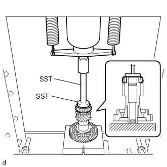
3. INSTALL COUNTER DRIVEN GEAR FRONT TAPERED ROLLER BEARING (INNER RACE)
| (a) Using SST and a press, install a new counter driven gear front tapered roller bearing (inner race) to the pinion and counter driven gear sub-assembly. SST: 09950-60011 09951-00550 SST: 09950-70010 09951-07150 NOTICE: Be sure to install the counter driven gear front tapered roller bearing (inner race) so that there is no clearance between the counter driven gear front tapered roller bearing (inner race) and the pinion and counter driven gear sub-assembly. If there is any clearance, the turning torque of the pinion and counter driven gear sub-assembly cannot be measured correctly. |
|
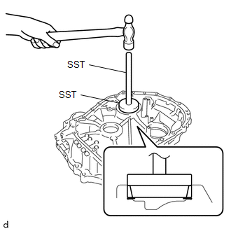
4. INSTALL COUNTER DRIVEN GEAR FRONT TAPERED ROLLER BEARING (OUTER RACE)
| (a) Using SST and a hammer, install a new counter driven gear front tapered roller bearing (outer race) and pinion and counter driven gear shim to the transaxle housing. SST: 09950-60021 09951-00780 SST: 09950-70010 09951-07150 NOTICE: Be sure to install the counter driven gear front tapered roller bearing (outer race) so that there is no clearance between the counter driven gear front tapered roller bearing (outer race), pinion and counter driven gear shim and the transaxle housing. If there is any clearance, the turning torque of the pinion and counter driven gear sub-assembly cannot be measured correctly. |
|
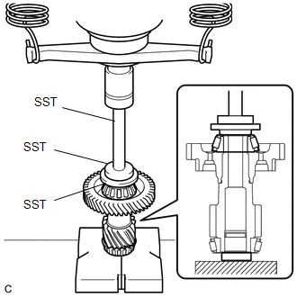
5. INSTALL COUNTER DRIVEN GEAR REAR TAPERED ROLLER BEARING (INNER RACE)
| (a) Using SST and a press, install a new counter driven gear rear tapered roller bearing (inner race) to the pinion and counter driven gear sub-assembly. SST: 09506-30012 SST: 09950-60011 09951-00420 09951-00550 SST: 09950-70010 09951-07150 NOTICE: Be sure to install the counter driven gear rear tapered roller bearing (inner race) so that there is no clearance between the counter driven gear rear tapered roller bearing (inner race) and the pinion and counter driven gear sub-assembly. If there is any clearance, the turning torque of the pinion and counter driven gear sub-assembly cannot be measured correctly. |
|
6. INSTALL COUNTER DRIVEN GEAR REAR TAPERED ROLLER BEARING (OUTER RACE)
| (a) Using SST and a hammer, install a new counter driven gear rear tapered roller bearing (outer race) to the automatic transaxle case sub-assembly. SST: 09950-60021 09951-00680 SST: 09950-70010 09951-07150 NOTICE: Be sure to install the counter driven gear rear tapered roller bearing (outer race) so that there is no clearance between the counter driven gear rear tapered roller bearing (outer race) and the automatic transaxle case sub-assembly. If there is any clearance, the turning torque of the pinion and counter driven gear sub-assembly cannot be measured correctly. |
|
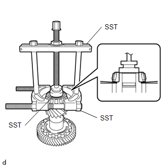
7. ADJUST FRONT DIFFERENTIAL CASE TAPERED ROLLER BEARING PRELOAD
(a) Remove any remaining seal packing from the contact surfaces of the transaxle housing and automatic transaxle case sub-assembly.
(b) Coat the front differential case front tapered roller bearing (inner race) and the front differential case rear tapered roller bearing (inner race) with a sufficient amount of Toyota Genuine ATF WS.
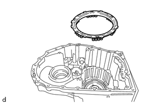
| (c) Install the differential case assembly to the automatic transaxle case sub-assembly. |
|
| (d) Install the transaxle housing to the automatic transaxle case sub-assembly with the 21 bolts (A and B). Torque: 29.4 N·m {300 kgf·cm, 22 ft·lbf} Bolt Length:
|
|
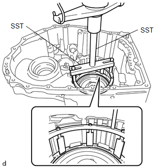
| (e) Using SST, rotate the differential case assembly 20 times or more to stabilize the bearing. SST: 09564-33010 |
|
| (f) Using SST and a torque wrench, measure the turning torque of the front differential case tapered roller bearing while rotating SST at 10 rpm. SST: 09564-33010 Standard Turning Torque: for TMC Made 0.69 to 1.02 N*m (8 to 10 kgf*cm, 7 to 9 in.*lbf) for TMMWV Made 0.99 to 1.28 N*m (11 to 13 kgf*cm, 9 to 11 in.*lbf) If the turning torque is not within the specified range, refer to the table below to select a shim so that the turning torque is within the specified range. Differential Drive Pinion Shim Thickness:
|
|
(g) Remove the 21 bolts and transaxle housing from the automatic transaxle case sub-assembly.
8. ADJUST PINION AND COUNTER DRIVEN GEAR TAPERED ROLLER BEARING PRELOAD
(a) Coat the counter driven gear front tapered roller bearing (inner race) and the counter driven gear rear tapered roller bearing (inner race) with a sufficient amount of Toyota Genuine ATF WS.
| (b) Install the pinion and counter driven gear sub-assembly to the automatic transaxle case sub-assembly. |
|
| (c) Install the transaxle housing to the automatic transaxle case sub-assembly with the 21 bolts (A and B). Torque: 29.4 N·m {300 kgf·cm, 22 ft·lbf} Bolt Length:
|
|
| (d) Using SST, rotate the differential case assembly 20 times or more to stabilize the bearing. SST: 09564-33010 |
|
| (e) Using SST and a torque wrench, measure the turning torque of the pinion and counter driven gear tapered roller bearing while rotating SST at 10 rpm. SST: 09564-33010 Standard Turning Torque: for TMC Made Front differential case tapered roller bearing preload + 0.99 to 2.26 N*m (11 to 23 kgf*cm, 9 to 20 in.*lbf) for TMMWV Made Front differential case tapered roller bearing preload + 1.75 to 2.61 N*m (18 to 26 kgf*cm, 16 to 23 in.*lbf) If the turning torque is not within the specified range, refer to the table below to select a shim so that the turning torque is within the specified range. Pinion and Counter Driven Gear Shim Thickness:
|
|
(f) Remove the 21 bolts and transaxle housing from the automatic transaxle case sub-assembly.
(g) Remove the pinion and counter driven gear sub-assembly from the automatic transaxle case sub-assembly.
(h) Remove the differential case assembly from the automatic transaxle case sub-assembly.
9. INSTALL NO. 2 TRANSAXLE CASE PLUG
(a) Clean the 6 No. 2 transaxle case plugs and 6 installation holes.
| (b) Apply adhesive to 2 or 3 threads on the end of the No. 2 transaxle case plug. Adhesive: Toyota Genuine Adhesive 1324, Three Bond 1324 or equivalent NOTICE: Make sure to install the No. 2 transaxle case plug immediately after applying adhesive to prevent foreign matter from attaching to them. |
|
| (c) Using a 6 mm socket hexagon wrench, install the 3 No. 2 transaxle case plugs and 3 new gaskets to the automatic transaxle case sub-assembly. Torque: 17 N·m {173 kgf·cm, 13 ft·lbf} |
|
| (d) Using a 6 mm socket hexagon wrench, install the 3 No. 2 transaxle case plugs and 3 new gaskets to the transaxle housing. Torque: 17 N·m {173 kgf·cm, 13 ft·lbf} |
|
10. INSTALL NO. 1 TRANSAXLE CASE PLUG
| (a) Coat 8 new O-rings with Toyota Genuine ATF WS and install them to the 8 No. 1 transaxle case plugs. |
|
| (b) Install the 4 No. 1 transaxle case plugs to the automatic transaxle case sub-assembly. Torque: 7.4 N·m {75 kgf·cm, 65 in·lbf} |
|
| (c) Install the 4 No. 1 transaxle case plugs to the transaxle housing. Torque: 7.4 N·m {75 kgf·cm, 65 in·lbf} |
|
11. INSTALL NEEDLE ROLLER BEARING
| (a) Using SST and a press, install a new needle roller bearing to the transaxle housing. SST: 09950-60011 09951-00560 SST: 09950-70010 09951-07200 NOTICE: Be careful not to damage the transaxle housing. |
|
12. INSTALL FRONT DRIVE SHAFT OIL SEAL LH
| (a) Using SST and a hammer, install a new front drive shaft oil seal LH to the automatic transaxle case sub-assembly. SST: 09649-17010 SST: 09950-70010 09951-07200 Standard Depth: -0.5 to 0.5 mm (-0.0197 to 0.0197 in.) |
|
13. INSTALL FRONT DRIVE SHAFT OIL SEAL RH
| (a) Using SST and a hammer, install a new front drive shaft oil seal RH to the transaxle housing. SST: 09316-10010 SST: 09950-70010 09951-07200 Standard Depth: -0.5 to 0.5 mm (-0.0197 to 0.0197 in.) |
|
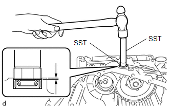
14. INSTALL TRANSAXLE CASE OIL SEAL
(a) Clean and degrease the oil seal press-in surface.
| (b) Using SST and a hammer, install a new transaxle case oil seal to the transaxle housing. SST: 09950-60011 09951-00640 SST: 09950-70010 09951-07200 Standard Depth: -0.5 to 0.5 mm (-0.0197 to 0.0197 in.) |
|
(c) Apply MP grease to the lip of the transaxle case oil seal.
15. INSTALL MANUAL VALVE LEVER SHAFT OIL SEAL
| (a) Using SST and a hammer, install a new manual valve lever shaft oil seal to the automatic transaxle case sub-assembly. SST: 09950-60011 09951-00210 SST: 09950-70010 09951-07200 Standard Depth: -0.3 to 0.4 mm (-0.0118 to 0.0157 in.) |
|
(b) Apply MP grease to the lip of the manual valve lever shaft oil seal.
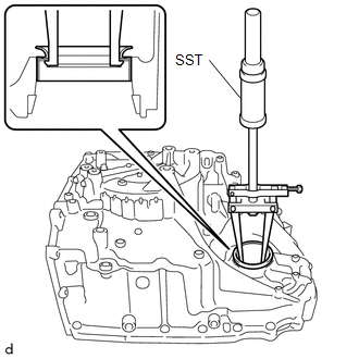
16. INSTALL NEEDLE ROLLER BEARING
| (a) Using SST and a press, install a new needle roller bearing to the automatic transaxle case sub-assembly. SST: 09950-60011 09951-00210 SST: 09950-70010 09951-07150 Standard Depth: 2.1 to 2.5 mm (0.0827 to 0.0984 in.) NOTICE: Install the needle roller bearing with its supplier name mark facing the front of the automatic transaxle assembly. |
|
17. INSTALL 1ST AND REVERSE BRAKE PISTON
| (a) Apply a light coat of Toyota Genuine ATF WS to 2 new O-rings and install them to the 1st and reverse brake piston. NOTICE:
|
|
| (b) Set the 1st and reverse brake return spring sub-assembly on the 1st and reverse brake piston. |
|
| (c) Install the 1st and reverse brake piston with 1st and reverse brake return spring sub-assembly to the automatic transaxle case sub-assembly. NOTICE: Make sure that the O-rings are not damaged or do not jump out of position during installation. |
|
18. INSTALL 1ST AND REVERSE BRAKE RETURN SPRING SUB-ASSEMBLY
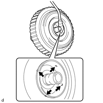
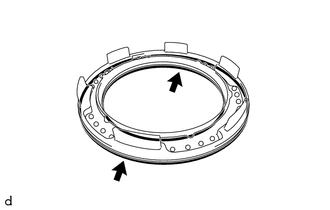
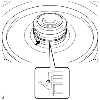
| (a) Set the snap ring on the automatic transaxle case sub-assembly as shown in the illustration. NOTICE: The opening of the snap ring should be within the area shown in the illustration (spline portion). |
|
| (b) Place SST on the 1st and reverse brake return spring sub-assembly and compress it with a press. SST: 09380-60011 09381-06020 09381-06050 09381-06060 09381-06100 09381-06110 SST: 09950-70010 09951-07200 NOTICE: Stop the press when the 1st and reverse brake return spring sub-assembly is flush with the snap ring groove. |
|
| (c) Using a screwdriver with its tip wrapped with protective tape, install the snap ring into the snap ring groove of the automatic transaxle case sub-assembly. NOTICE:
|
|
19. INSTALL NO. 2 1ST AND REVERSE BRAKE PISTON
| (a) Install the No. 2 1st and reverse brake piston to the automatic transaxle case sub-assembly. |
|
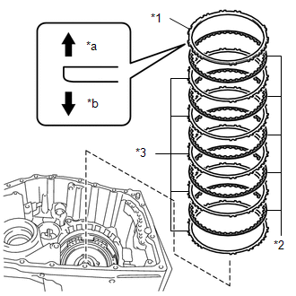
20. INSTALL 2ND BRAKE BRAKE DISC
| (a) Install the 5 2nd brake brake plates, 5 2nd brake brake discs and 2nd brake brake flange to the automatic transaxle case sub-assembly. NOTICE: Assemble the 2nd brake brake flange with its tapered surface facing toward the 2nd brake brake disc. |
|
| (b) Using a screwdriver with its tip wrapped with protective tape, install the snap ring to the automatic transaxle case sub-assembly. NOTICE: The opening of the snap ring should be within the area shown in the illustration (spline portion). |
|
21. INSPECT CLEARANCE OF B-2 BRAKE
Click here

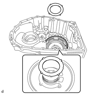
22. INSTALL DIRECT CLUTCH DRUM OIL SEAL RING
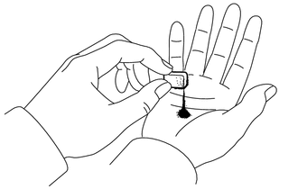
(a) Apply a small amount of MP grease to the entire circumference of the direct clutch drum oil seal ring installation groove portion.
HINT:
By applying MP grease, the wobble within the direct clutch drum oil seal ring installation groove will be eliminated, preventing damage to the direct clutch drum oil seal ring at the time of front planetary gear assembly installation.
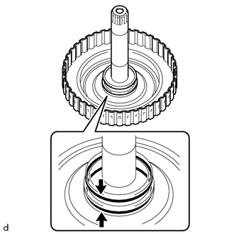
| (b) Coat 2 new direct clutch drum oil seal rings with Toyota Genuine ATF WS and install them to the automatic transaxle case sub-assembly. NOTICE: While making the spread of the opening of the direct clutch drum oil seal ring as small as possible, install it to the automatic transaxle case sub-assembly. If the ring opening is spread, briefly hold it closed with your fingers to return it to its original condition. |
|
23. INSTALL C-2 CLUTCH PISTON
| (a) Apply a light coat of Toyota Genuine ATF WS to 2 new O-rings and install it to the intermediate shaft sub-assembly. NOTICE: Be careful not to damage or twist the O-ring. |
|
(b) Apply a light coat of Toyota Genuine ATF WS to the lip seal of the C-2 clutch piston.
| (c) Install the C-2 clutch piston to the intermediate shaft sub-assembly. NOTICE:
|
|
24. INSTALL CLUTCH RETURN SPRING SUB-ASSEMBLY
| (a) Install the clutch return spring sub-assembly to the intermediate shaft sub-assembly. |
|
25. INSTALL C-2 CLUTCH BALANCER
(a) Apply a light coat of Toyota Genuine ATF WS to the lip seal of the C-2 clutch balancer.
| (b) Install the C-2 clutch balancer to the intermediate shaft sub-assembly. NOTICE: Be careful not to damage the lip seal of the C-2 clutch balancer. NOTICE:
|
|
| (c) Place SST on the C-2 clutch balancer and compress the clutch return spring sub-assembly with a press. SST: 09387-00020 NOTICE: Stop the press when the clutch return spring sub-assembly is flush with the snap ring groove. |
|
(d) Using SST, install the snap ring to the intermediate shaft sub-assembly.
SST: 09350-30020
09350-07070
NOTICE:
Make sure that the snap ring is installed in the groove of the intermediate shaft sub-assembly correctly.
26. INSTALL NO. 2 CLUTCH DISC
| (a) Install the 4 No. 2 clutch plates, 4 No. 2 clutch discs and direct clutch flange to the intermediate shaft sub-assembly. NOTICE:
|
|
| (b) Using a screwdriver with its tip wrapped in protective tape, install the snap ring to the intermediate shaft sub-assembly. NOTICE:
|
|
27. INSTALL NO. 1 THRUST BEARING RACE
| (a) Coat the No. 1 thrust bearing race with Toyota Genuine ATF WS and install it to the automatic transaxle case sub-assembly. No. 1 Thrust Bearing Race Diameter:
NOTICE: Securely insert the claw of the No. 1 thrust bearing race into the hole of the automatic transaxle case sub-assembly. |
|
28. INSTALL THRUST NEEDLE ROLLER BEARING
| (a) Coat the thrust needle roller bearing with Toyota Genuine ATF WS and install it to the C-2 clutch assembly. Thrust Needle Roller Bearing Diameter:
NOTICE: Make sure to assemble the thrust needle roller bearing in the correct direction. HINT: When installing the C-2 clutch assembly, if the thrust needle roller bearing falls off, coat the C-2 clutch assembly installation surface with MP grease and install the parts. |
|
29. INSTALL C-2 CLUTCH ASSEMBLY
| (a) Install the C-2 clutch assembly to the automatic transaxle case sub-assembly. |
|
30. INSPECT CLEARANCE OF C-2 CLUTCH
Click here
31. INSTALL NO. 4 PLANETARY CARRIER THRUST WASHER
| (a) Install the No. 4 planetary carrier thrust washer to the rear planetary gear assembly. HINT:
|
|
32. INSTALL REAR PLANETARY GEAR ASSEMBLY
| (a) Install the rear planetary gear assembly to the C-2 clutch assembly. |
|
33. INSTALL NO. 2 THRUST BEARING RACE
| (a) Coat the No. 2 thrust bearing race with Toyota Genuine ATF WS and install it to the C-2 clutch assembly. No. 2 Thrust Bearing Race Diameter:
|
|
34. INSTALL THRUST NEEDLE ROLLER BEARING
| (a) Coat the thrust needle roller bearing with Toyota Genuine ATF WS and install it to the C-2 clutch assembly. Thrust Needle Roller Bearing Diameter:
|
|
35. INSTALL NO. 3 THRUST BEARING RACE
| (a) Coat the No. 3 thrust bearing race with Toyota Genuine ATF WS and install it to the rear planetary sun gear sub-assembly. No. 3 Thrust Bearing Race Diameter:
HINT: When installing the rear planetary sun gear sub-assembly, if the No. 3 thrust bearing race falls off, coat the rear planetary sun gear sub-assembly installation surface with MP grease and install the parts. |
|
36. INSTALL REAR PLANETARY SUN GEAR SUB-ASSEMBLY
| (a) Install the rear planetary sun gear sub-assembly to the C-2 clutch assembly. |
|
37. INSTALL THRUST BEARING RACE
| (a) Coat the thrust bearing race with Toyota Genuine ATF WS and install it to the rear planetary sun gear sub-assembly. Thrust Bearing Race Diameter:
|
|
38. INSTALL THRUST NEEDLE ROLLER BEARING
| (a) Coat the thrust needle roller bearing with Toyota Genuine ATF WS and install it to the rear planetary sun gear sub-assembly. Thrust Needle Roller Bearing Diameter:
|
|
39. INSTALL NO. 4 THRUST BEARING RACE
| (a) Coat the No. 4 thrust bearing race with Toyota Genuine ATF WS and install it to the rear planetary sun gear sub-assembly. No. 4 Thrust Bearing Race Diameter:
|
|
40. INSTALL PLANETARY SUN GEAR SUB-ASSEMBLY
| (a) Install the planetary sun gear sub-assembly to the rear planetary gear assembly. |
|
41. INSTALL NO. 3 PLANETARY CARRIER THRUST WASHER
| (a) Coat the No. 3 planetary carrier thrust washer with Toyota Genuine ATF WS and install it to the rear planetary gear assembly. NOTICE: Securely insert the claw of the No. 3 planetary carrier thrust washer into the hole of the rear planetary gear assembly. |
|
42. INSTALL NO. 1 BRAKE DISC
| (a) Install the 4 No. 1 brake plates, 4 No. 1 brake discs and No. 1 brake flange to the counter drive gear sub-assembly. NOTICE:
|
|
| (b) Using a screwdriver with its tip wrapped in protective tape, install the snap ring to the counter drive gear sub-assembly. NOTICE:
|
|
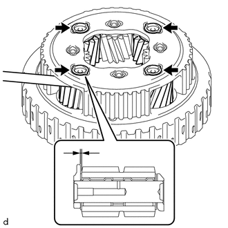
43. INSTALL COUNTER DRIVE GEAR SUB-ASSEMBLY
(a) Clean and degrease the counter drive gear sub-assembly installation bolts and the 8 bolt holes.
NOTICE:
If the bolts are tightened without cleaning and degreasing the bolts and bolt holes, the tightening torque will be too high and the counter drive gear sub-assembly or automatic transaxle case sub-assembly may be damaged.
| (b) Coat a new O-ring with Toyota Genuine ATF WS and install it to the automatic transaxle case sub-assembly. |
|
| (c) Install the counter drive gear sub-assembly together with the pinion and counter driven gear sub-assembly to the automatic transaxle case sub-assembly. |
|
| (d) Temporarily install the 8 bolts (A and B). HINT: Bolt (A) is a hexagon socket head cap bolt. |
|
(e) Fully tighten the 6 bolts (B).
Torque:
76 N·m {775 kgf·cm, 56 ft·lbf}
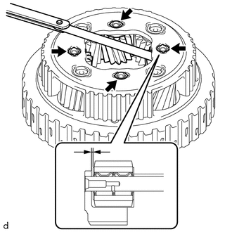
(f) Using a T50 "TORX" socket wrench, fully tighten the 2 bolts (A).
Torque:
31.8 N·m {324 kgf·cm, 23 ft·lbf}
44. INSPECT CLEARANCE OF B-1 BRAKE
Click here
45. INSTALL PARKING LOCK SLEEVE
| (a) Coat the parking lock sleeve with Toyota Genuine ATF WS and install it to the automatic transaxle case sub-assembly. |
|
46. INSTALL PARKING LOCK PAWL
| (a) Coat the parking lock pawl with Toyota Genuine ATF WS and install it to the automatic transaxle case sub-assembly. |
|
47. INSTALL PARKING LOCK PAWL SHAFT
| (a) Coat the parking lock pawl shaft with Toyota Genuine ATF WS and install it to the automatic transaxle case sub-assembly. |
|
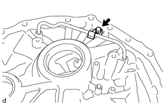
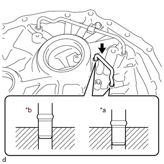
48. INSTALL PARKING LOCK PAWL TORSION SPRING
| (a) Install the parking lock pawl torsion spring to the automatic transaxle case sub-assembly as shown in the illustration. NOTICE: Securely insert the parking lock pawl torsion spring all the way into the parking lock pawl shaft. |
|
49. INSTALL MANUAL VALVE LEVER SHAFT SUB-ASSEMBLY
| (a) Install the manual valve lever shaft sub-assembly to the automatic transaxle case sub-assembly. NOTICE: When installing the manual valve lever shaft sub-assembly, be careful not to damage the manual valve lever shaft oil seal. |
|
50. INSTALL PARKING LOCK ROD SUB-ASSEMBLY
| (a) Parking lock rod sub-assembly as shown in the illustration, and install the parking lock rod sub-assembly. NOTICE: Securely align the cutouts of the parking lock rod sub-assembly and manual valve lever shaft sub-assembly. |
|
51. INSTALL MANUAL VALVE LEVER SHAFT RETAINER SPRING
| (a) Install the manual valve lever shaft retainer spring to the automatic transaxle case sub-assembly. |
|
52. INSTALL PAWL STOPPER PLATE
| (a) Install the pawl stopper plate to the automatic transaxle case sub-assembly with the 2 bolts. Torque: 9.8 N·m {100 kgf·cm, 87 in·lbf} |
|
53. INSTALL MANUAL VALVE LEVER SUB-ASSEMBLY
| (a) Install the manual valve lever sub-assembly to the automatic transaxle case sub-assembly. NOTICE: The pin portion of the manual valve lever shaft sub-assembly must be inserted into the slot of the manual valve lever sub-assembly. |
|
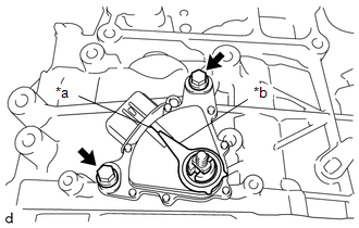
54. INSTALL MANUAL VALVE LEVER SHAFT SUB-ASSEMBLY
| (a) Coat a new O-ring with Toyota Genuine ATF WS and install it to the manual valve lever shaft sub-assembly. NOTICE: Ensure that the O-ring it not twisted. |
|
| (b) Align the cutouts of the manual valve lever sub-assembly and manual valve lever shaft sub-assembly, and install the manual valve lever shaft sub-assembly. HINT: Installing the manual valve lever shaft sub-assembly to the area shown in the illustration will align the cutouts. |
|
| (c) Secure the manual valve lever shaft sub-assembly to the automatic transaxle case sub-assembly with the bolt. Torque: 9.8 N·m {100 kgf·cm, 87 in·lbf} |
|
55. INSTALL NO. 5 THRUST BEARING RACE
| (a) Coat the No. 5 thrust bearing race with Toyota Genuine ATF WS and install it to the sun gear input hub sub-assembly. No. 5 Thrust Bearing Race Diameter:
|
|
56. INSTALL THRUST NEEDLE ROLLER BEARING
| (a) Coat the thrust needle roller bearing with Toyota Genuine ATF WS and install it to the sun gear input hub sub-assembly. Thrust Needle Roller Bearing Diameter:
|
|
57. INSTALL SUN GEAR INPUT HUB SUB-ASSEMBLY
| (a) Install the sun gear input hub sub-assembly to the counter drive gear sub-assembly. |
|
58. INSTALL FORWARD CLUTCH PISTON
| (a) Apply a light coat of Toyota Genuine ATF WS to a new D-ring and install it to the clutch drum sub-assembly. HINT:
|
|
| (b) Apply a light coat of Toyota Genuine ATF WS to a new O-ring and install it to the clutch drum sub-assembly. NOTICE: Be careful not to damage or twist the O-ring. |
|
| (c) Apply a light coat of Toyota Genuine ATF WS to the forward clutch piston and install it to the clutch drum sub-assembly. NOTICE:
|
|
59. INSTALL REAR CLUTCH PISTON RETURN COMPRESSION SPRING
| (a) Install the rear clutch piston return compression spring to the forward clutch piston. NOTICE: Make sure to install in the correct direction. |
|
60. INSTALL NO. 1 CLUTCH BALANCER
(a) Apply a light coat of Toyota Genuine ATF WS to the lip seal of the forward clutch piston.
| (b) Install the No. 1 clutch balancer to the forward clutch piston. NOTICE: Be careful not to damage the lip seal of the forward clutch piston. |
|
| (c) Place SST on the No. 1 clutch balancer and compress the rear clutch piston return compression spring with a press. SST: 09387-00020 NOTICE: Stop the press when the rear clutch piston return compression spring is flush with the snap ring groove. |
|
(d) Using SST, install the snap ring to the clutch drum sub-assembly.
SST: 09350-30020
09350-07070
NOTICE:
Make sure that the snap ring is installed in the groove of the clutch drum sub-assembly correctly.
61. INSTALL FRONT CLUTCH CLUTCH DISC
| (a) Install the 5 forward multiple disc clutch clutch plates, 5 front clutch clutch discs and forward clutch flange to the clutch drum sub-assembly. NOTICE:
|
|
| (b) Using a screwdriver with its tip wrapped in protective tape, install the snap ring to the clutch drum sub-assembly. NOTICE:
|
|
62. INSPECT CLEARANCE OF C-1 CLUTCH
Click here
63. INSTALL C-1 CLUTCH ASSEMBLY
| (a) Install the C-1 clutch assembly to the sun gear input hub sub-assembly. |
|
64. INSTALL NO. 6 THRUST BEARING RACE
| (a) Coat the No. 6 thrust bearing race with Toyota Genuine ATF WS and install it to the C-1 clutch assembly. No. 6 Thrust Bearing Race Diameter:
|
|
65. INSTALL THRUST NEEDLE ROLLER BEARING
| (a) Coat the thrust needle roller bearing with Toyota Genuine ATF WS and install it to the C-1 clutch assembly. Thrust Needle Roller Bearing Diameter:
|
|
66. INSTALL FRONT PLANETARY RING GEAR
| (a) Install the front planetary ring gear flange to the front planetary ring gear. |
|
| (b) Using a screwdriver with its tip wrapped with protective tape, install the snap ring to the front planetary ring gear. NOTICE: Be careful not to damage the front planetary ring gear and front planetary ring gear flange. |
|
| (c) Install the front planetary ring gear with front planetary ring gear flange to the C-1 clutch assembly. |
|
67. INSTALL REAR INPUT SHAFT OIL SEAL RING
| (a) Apply a small amount of MP grease to the entire circumference of the rear input shaft oil seal ring installation groove portion. HINT: By applying MP grease, the wobble within the rear input shaft oil seal ring installation groove will be eliminated, preventing damage to the rear input shaft oil seal ring at the time of front planetary gear assembly installation. |
|
(b) Coat 2 new rear input shaft oil seal rings with Toyota Genuine ATF WS and install them to the front planetary gear assembly.
NOTICE:
While making the spread of the opening of the rear input shaft oil seal ring as small as possible, install it to the front planetary gear assembly. If the ring opening is spread, briefly hold it closed with your fingers to return it to its original condition.
68. INSTALL INPUT SHAFT OIL SEAL RING
| (a) Apply a small amount of MP grease to the entire circumference of the input shaft oil seal ring installation groove portion. HINT: By applying MP grease, the wobble within the input shaft oil seal ring installation groove will be eliminated, preventing damage to the input shaft oil seal ring at the time of front oil pump assembly and torque converter clutch assembly installation. |
|
(b) Coat 5 new input shaft oil seal rings with Toyota Genuine ATF WS and install them to the front planetary gear assembly.
NOTICE:
While making the spread of the opening of the input shaft oil seal ring as small as possible, install it to the front planetary gear assembly. If the ring opening is spread, briefly hold it closed with your fingers to return it to its original condition.
69. INSTALL NO. 7 THRUST BEARING RACE
| (a) Coat the No. 7 thrust bearing race with Toyota Genuine ATF WS and install it to the front planetary gear assembly. No. 7 Thrust Bearing Race Diameter:
NOTICE: Securely insert the claw of the No. 7 thrust bearing race into the hole of the front planetary gear assembly. HINT: When installing the front planetary gear assembly, if the No. 7 thrust bearing race falls off, coat the front planetary gear assembly installation surface with MP grease and install the parts. |
|
70. INSTALL THRUST NEEDLE ROLLER BEARING
| (a) Coat the thrust needle roller bearing with Toyota Genuine ATF WS and install it to the front planetary ring gear. Thrust Needle Roller Bearing Diameter:
|
|
71. INSTALL FRONT PLANETARY GEAR ASSEMBLY
| (a) Install the front planetary gear assembly to the front planetary ring gear. |
|
72. INSTALL NO. 8 THRUST BEARING RACE
| (a) Coat the No. 8 thrust bearing race with Toyota Genuine ATF WS and install it to the front planetary ring gear. No. 8 Thrust Bearing Race Diameter:
|
|
73. INSTALL THRUST NEEDLE ROLLER BEARING
| (a) Coat the thrust needle roller bearing with Toyota Genuine ATF WS and install it to the front planetary ring gear. Thrust Needle Roller Bearing Diameter:
|
|
74. INSTALL NO. 9 THRUST BEARING RACE
| (a) Coat the No. 9 thrust bearing race with Toyota Genuine ATF WS and install it to the front planetary ring gear. No. 9 Thrust Bearing Race Diameter:
|
|
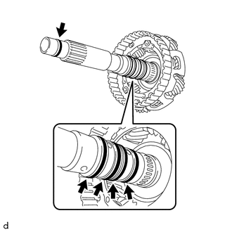
75. INSTALL PLANETARY SUN GEAR
| (a) Install the planetary sun gear to the front planetary gear assembly. |
|
76. INSTALL NO. 2 PLANETARY CARRIER THRUST WASHER
| (a) Install the No. 2 planetary carrier thrust washer to the front planetary gear assembly. NOTICE: Securely insert each protrusion of the No. 2 planetary carrier thrust washer into each indentation of the front planetary gear assembly. |
|
77. INSPECT CLEARANCE OF C-4 CLUTCH
Click here
78. INSPECT CLEARANCE OF C-3 CLUTCH
Click here
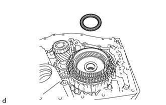
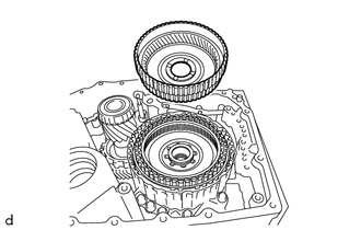
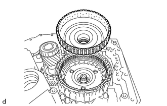
79. INSTALL C-3 AND C-4 CLUTCH ASSEMBLY
| (a) Install the C-3 and C-4 clutch assembly to the front planetary gear assembly. |
|
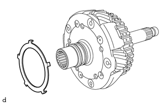
80. INSTALL PLANETARY CARRIER THRUST WASHER
| (a) Install the planetary carrier thrust washer to the C-3 and C-4 clutch assembly. NOTICE: Securely insert the protrusion of the planetary carrier thrust washer into the indentation of the C-3 and C-4 clutch assembly. |
|
81. INSTALL FRONT OIL PUMP ASSEMBLY
| (a) Install the front oil pump assembly to the automatic transaxle case sub-assembly with the 7 bolts. Torque: 24.5 N·m {250 kgf·cm, 18 ft·lbf} Bolt Length:
|
|
82. INSTALL MANUAL DETENT SPRING SUB-ASSEMBLY
| (a) Install the manual detent spring sub-assembly to the front oil pump assembly with the bolt. Torque: 9.8 N·m {100 kgf·cm, 87 in·lbf} NOTICE:
|
|
83. INSTALL OIL PUMP SPROCKET REAR THRUST WASHER
| (a) Install the oil pump sprocket rear thrust washer to the front oil pump assembly. NOTICE: Securely insert the protrusion of the oil pump sprocket rear thrust washer into the indentation of the front oil pump assembly. |
|
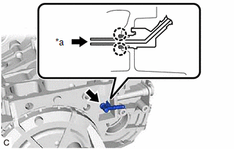
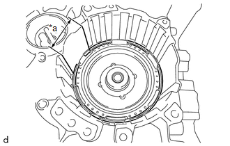
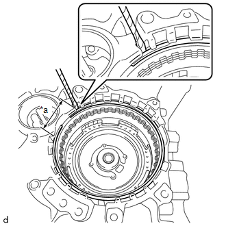
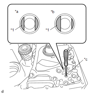
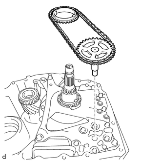
84. INSTALL TRANSMISSION DRIVE CHAIN
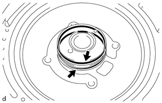
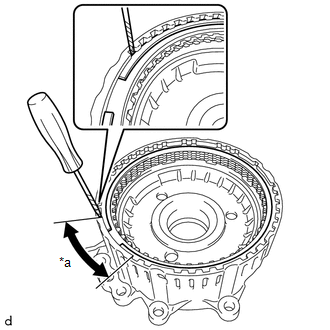
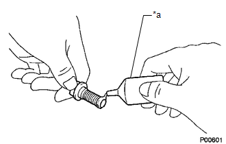
| (a) Using a screwdriver with its tip wrapped in protective tape, align the cutout of the front oil pump drive gear with the position (*a) shown in the illustration. NOTICE: Do not pry with excessive force when aligning the cutout of the front oil pump drive gear. |
|
| (b) Install the transmission drive chain together with the transmission oil pump drive sprocket and oil pump drive shaft sub-assembly to the front oil pump assembly. NOTICE:
|
|
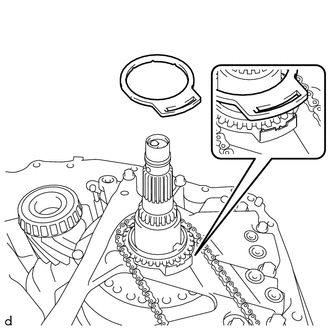
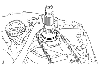
85. INSTALL OIL PUMP SPROCKET FRONT THRUST WASHER
| (a) Install the oil pump sprocket front thrust washer to the transmission oil pump drive sprocket. NOTICE: Securely insert the long protrusion of the oil pump sprocket rear thrust washer into the slot of the oil pump sprocket front thrust washer. |
|
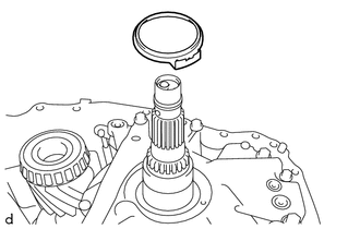
86. INSTALL CLUTCH DRUM OIL SEAL RING
| (a) Apply a small amount of MP grease to the entire circumference of the clutch drum oil seal ring installation groove portion. HINT: By applying MP grease, the wobble within the clutch drum oil seal ring installation groove will be eliminated, preventing damage to the clutch drum oil seal ring at the time of torque converter clutch assembly installation. |
|
(b) Coat a new clutch drum oil seal ring with Toyota Genuine ATF WS and install it to the front oil pump assembly.
NOTICE:
While making the spread of the opening of the clutch drum oil seal ring as small as possible, install it to the front oil pump assembly. If the ring opening is spread, briefly hold it closed with your fingers to return it to its original condition.
87. INSTALL DIFFERENTIAL CASE ASSEMBLY
| (a) Install the differential case assembly to the automatic transaxle case sub-assembly. |
|
88. INSTALL TRANSMISSION LUBE APPLY TUBE
| (a) Install the transmission lube apply tube to the transaxle housing. NOTICE: Insert the transmission lube apply tube until its spool portion is contacting the transaxle housing. |
|
| (b) Install the clamp to the transaxle housing with the bolt. Torque: 5.4 N·m {55 kgf·cm, 48 in·lbf} |
|
89. INSTALL DIFFERENTIAL GEAR LUBE APPLY TUBE
| (a) Install the differential gear lube apply tube to the transaxle housing. NOTICE: Insert the differential gear lube apply tube until its spool portion is contacting the transaxle housing. |
|
90. INSTALL TRANSMISSION OIL CLEANER MAGNET
| (a) Install the 3 transmission oil cleaner magnets to the transaxle housing oil separator. |
|
91. INSTALL TRANSAXLE HOUSING OIL SEPARATOR
| (a) Install the transaxle housing oil separator to the transaxle housing with the 3 bolts. Torque: 5.4 N·m {55 kgf·cm, 48 in·lbf} |
|
92. INSTALL TRANSAXLE HOUSING
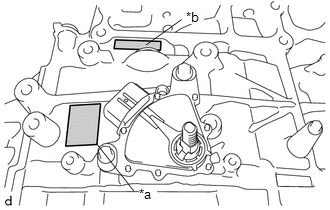
HINT:
TMC Made and TMMWV Made components can be identified by the location where the serial number is stamped.
|
*a | TMC Made |
|
*b | TMMWV Made |
NOTICE:
When installing the transaxle housing check that the transmission drive chain rotates smoothly.
(a) Peel off the old seal packing from the transaxle housing and automatic transaxle case sub-assembly installation surface, and clean it.
NOTICE:
Do not damage the installation surface.
| (b) Clean the 21 bolts and bolt holes in the automatic transaxle case sub-assembly. |
|
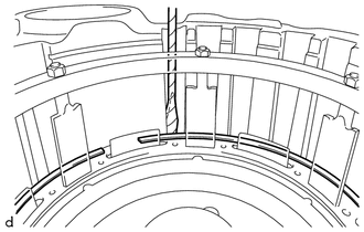
(c) Clean the inner chamfer of the automatic transaxle case sub-assembly shown in the illustration.
 |
Area to be Cleaned |
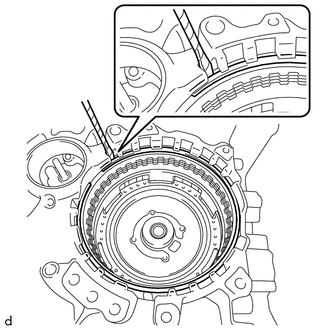
| (d) Apply seal packing to the automatic transaxle case sub-assembly as shown in the illustration. Seal Packing: Toyota Genuine Seal Packing 1281, Three Bond 1281 or equivalent Standard Seal Diameter: 1.8 mm (0.0709 in.) NOTICE: After applying seal packing, install the transaxle housing within 3 minutes and tighten the bolts within 20 minutes of applying the seal packing. |
|
| (e) Coat 5 new transaxle case gaskets with Toyota Genuine ATF WS and install it to the front oil pump assembly. |
|
(f) Coat a new O-ring with Toyota Genuine ATF WS and install it to the automatic transaxle case sub-assembly.
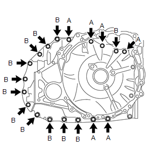
(g) for TMC Made:
| (1) Install the transaxle housing to the automatic transaxle case sub-assembly with the 9 bolts (A) and 12 bolts (B). Torque: 29.4 N·m {300 kgf·cm, 22 ft·lbf} Bolt Length:
|
|
(h) for TMMWV Made:
| (1) Install the transaxle housing to the automatic transaxle case sub-assembly with the 6 bolts (A) and 12 bolts (B). Torque: Bolt (A) and (B) : 29.4 N·m {300 kgf·cm, 22 ft·lbf} Bolt Length:
|
|
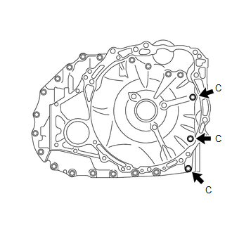
| (2) Apply adhesive to 2 or 3 threads on the end of the 3 bolts (C). Bolt Length: 40 mm (1.57 in.) Adhesive: Toyota Genuine Adhesive 1324, Three Bond 1324 or equivalent NOTICE: Make sure to install the bolts immediately after applying adhesive to prevent foreign matter from attaching to them. HINT: The 3 bolts (C) are in the locations shown in the following step. |
|
| (3) Install the 3 bolts (C). Torque: Bolt (C) : 22.7 N·m {231 kgf·cm, 17 ft·lbf} |
|
93. INSPECT INPUT SHAFT END PLAY
Click here
94. INSTALL TRANSMISSION REVOLUTION SENSOR (NC)
| (a) Install the transmission revolution sensor (NC) and spacer to the counter drive gear sub-assembly with the bolt. Torque: 5.4 N·m {55 kgf·cm, 48 in·lbf} |
|
95. INSTALL TRANSMISSION REVOLUTION SENSOR (NT)
| (a) Install the transmission revolution sensor (NT) to the automatic transaxle case sub-assembly with the bolt. Torque: 5.4 N·m {55 kgf·cm, 48 in·lbf} |
|
96. INSTALL TRANSMISSION VALVE BODY ASSEMBLY
| (a) Coat 2 new transaxle case gaskets with Toyota Genuine ATF WS and install them to the automatic transaxle case sub-assembly. |
|
(b) Coat a new transaxle case gasket with Toyota Genuine ATF WS and install it to the counter drive gear sub-assembly.
(c) Coat a new No. 1 front oil pump cover gasket with Toyota Genuine ATF WS and install it to the front oil pump assembly.
(d) Coat a new No. 2 front oil pump cover gasket with Toyota Genuine ATF WS and install it to the front oil pump assembly.
| (e) Align the slit portion of the manual valve and the manual valve lever sub-assembly as shown in the illustration, and install the transmission valve body assembly to the automatic transaxle case sub-assembly with the 9 bolts. Torque: 10.8 N·m {110 kgf·cm, 8 ft·lbf} NOTICE: Be careful that the transmission revolution sensor (NC) wire is not pinched. |
|
(f) Engage the clamp to connect the transmission revolution sensor (NC) wire connector.
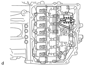
|
|
Do not let transmission revolution sensor (NC) wire ride up over this area. |
NOTICE:
To prevent it from being pinched between the transmission valve body assembly and the transmission case side cover, do not let the transmission revolution sensor (NC) wire ride up over the area shown in the illustration.
97. INSTALL TRANSMISSION WIRE
| (a) Coat the O-ring of the transmission wire with Toyota Genuine ATF WS. |
|
| (b) Install the transmission wire to the automatic transaxle case sub-assembly with the bolt. Torque: 5.4 N·m {55 kgf·cm, 48 in·lbf} |
|
| (c) Connect the transmission revolution sensor (NT) connector and transmission revolution sensor (NC) connector. |
|
(d) Install the temperature sensor to the transmission valve body assembly with the bolt and temperature sensor clamp.
Torque:
10.8 N·m {110 kgf·cm, 8 ft·lbf}
NOTICE:
To prevent it from being pinched between the transmission valve body assembly and the transmission case side cover, pass the transmission revolution sensor (NC) wire under the transmission wire (temperature sensor wire) as shown in the illustration.
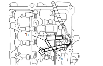
|
*a | Transmission Wire (Temperature Sensor Wire) |
|
*b | Transmission Revolution Sensor (NC) Wire |

(e) Connect the 9 solenoid valve connectors.
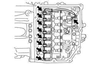
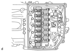
|
|
Do not let transmission wire protrude into this area. |
| (f) Engage the clamp to connect the transmission wire to the solenoid lock plate. |
|
98. INSTALL TRANSMISSION CASE SIDE COVER (for TMC Made)
HINT:
TMC Made and TMMWV Made components can be identified by the location where the serial number is stamped.
|
*a | TMC Made |
|
*b | TMMWV Made |
(a) Clean the transmission case side cover installation surface of the automatic transaxle case sub-assembly.
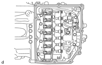
|
|
Area to be Cleaned |
NOTICE:
Completely remove any oil or grease from the contact surfaces of the automatic transaxle case sub-assembly.
| (b) Temporarily install a new transmission case side cover to the automatic transaxle case sub-assembly with the 2 bolts (A and B). NOTICE: To avoid damaging the gasket, prevent it from contacting the surrounding area during installation procedures. |
|
(c) Temporarily install the 8 bolts (C).
| (d) Fully tighten the 10 bolts in the order shown in the illustration. Torque: 7.0 N·m {71 kgf·cm, 62 in·lbf} |
|
99. INSTALL TRANSMISSION CASE SIDE COVER (for TMMWV Made)
HINT:
TMC Made and TMMWV Made components can be identified by the location where the serial number is stamped.
|
*a | TMC Made |
|
*b | TMMWV Made |
(a) Clean the transmission case side cover installation surface of the automatic transaxle case sub-assembly.
|
|
Area to be Cleaned |
NOTICE:
Completely remove any oil or grease from the contact surfaces of the automatic transaxle case sub-assembly.
| (b) Clean the 3 bolt holes shown in the illustration. |
|
| (c) Apply adhesive to 2 or 3 threads on the end of the bolt (A) and 2 bolts (D). Adhesive: Toyota Genuine Adhesive 1324, Three Bond 1324 or equivalent NOTICE: Make sure to install the bolts immediately after applying adhesive to prevent foreign matter from attaching to them. HINT: The bolt (A) and 2 bolts (D) are in the locations shown in the following step. |
|
| (d) Temporarily install a new transmission case side cover to the automatic transaxle case sub-assembly with the 2 bolts ((A) and (B)). NOTICE:
|
|
(e) Temporarily install the 6 bolts (C) and 2 bolts (D).
NOTICE:
Bolt (D) is an adhesive-coated bolt.
| (f) Fully tighten the 10 bolts in the order shown in the illustration. Torque: Bolt (A) and Bolt (D) : 6.5 N·m {66 kgf·cm, 58 in·lbf} Bolt (B) and Bolt (C) : 7.0 N·m {71 kgf·cm, 62 in·lbf} |
|
100. INSTALL NO. 1 BREATHER PLUG (ATM)
(a) Coat the O-ring portion of the No. 1 breather plug (ATM) with Toyota Genuine ATF WS.
| (b) Engage each claw to install a new No. 1 breather plug (ATM) to the automatic transaxle case sub-assembly. NOTICE: Securely push in the automatic transaxle case sub-assembly until the No. 1 breather plug (ATM) is engaged. HINT: Install the No. 1 breather plug (ATM) with its detent aligned with the indented portion of the automatic transaxle case sub-assembly. |
|
101. INSTALL NO. 1 OIL COOLER OUTLET TUBE SUB-ASSEMBLY
| (a) Coat a new O-ring with Toyota Genuine ATF WS and install it to the No. 1 oil cooler outlet tube sub-assembly. NOTICE: Ensure that the O-ring is not twisted. |
|
| (b) Using a 19 mm union nut wrench, install the No. 1 oil cooler outlet tube sub-assembly to the automatic transaxle case sub-assembly. Torque: Specified tightening torque : 31.1 N·m {317 kgf·cm, 23 ft·lbf} HINT:
|
|
102. INSTALL OIL COOLER UNION SUB-ASSEMBLY
| (a) Pass the oil cooler union sub-assembly through 2 new gaskets and temporarily install it to the automatic transaxle case sub-assembly. |
|
(b) Temporarily install the oil cooler union sub-assembly bracket portion to the automatic transaxle case sub-assembly with the bolt.
(c) Fully tighten the oil cooler union bolt.
Torque:
22.6 N·m {230 kgf·cm, 17 ft·lbf}
(d) Fully tighten the bolt.
Torque:
12 N·m {122 kgf·cm, 9 ft·lbf}
103. INSTALL NO. 1 TRANSMISSION OIL FILLER TUBE
| (a) Using a 6 mm socket hexagon wrench, install the No. 1 transmission oil filler tube to the transaxle housing. Torque: 1.7 N·m {17 kgf·cm, 15 in·lbf} |
|
104. INSTALL OVERFLOW PLUG
| (a) Using a 10 mm socket hexagon wrench, install the overflow plug and a new gasket to the transaxle housing. Torque: 50 N·m {510 kgf·cm, 37 ft·lbf} NOTICE: To prevent the gasket from being deformed when tightening, coat the gasket with Toyota Genuine ATF WS. |
|
105. INSTALL REFILL PLUG
|
(a) Install the refill plug and a new gasket to the automatic transaxle case sub-assembly. Torque: 49 N·m {500 kgf·cm, 36 ft·lbf} NOTICE: To prevent the gasket from being deformed when tightening, coat the gasket with Toyota Genuine ATF WS. |
|
106. INSTALL PARK/NEUTRAL POSITION SWITCH ASSEMBLY
| (a) Temporarily install the park/neutral position switch assembly to the automatic transaxle case sub-assembly with the 2 bolts. |
|
| (b) Temporarily install the transmission control shaft lever to the manual valve lever shaft sub-assembly. |
|
| (c) Turn the transmission control shaft lever clockwise until it stops, then turn it counterclockwise 2 notches. |
|
(d) Remove the transmission control shaft lever from the manual valve lever shaft sub-assembly.
| (e) Align the protrusion with the neutral basic line. |
|
(f) Hold the park/neutral position switch assembly in that position and tighten the 2 bolts.
Torque:
5.4 N·m {55 kgf·cm, 48 in·lbf}
107. INSTALL TRANSMISSION CONTROL SHAFT LEVER
| (a) Install the transmission control shaft lever to the manual valve lever shaft sub-assembly with the washer and nut. NOTICE: Be careful of the assembly direction of the transmission control shaft lever. Torque: 12.7 N·m {130 kgf·cm, 9 ft·lbf} |
|
Toyota Avalon (XX50) 2019-2022 Service & Repair Manual > Audio And Visual System(for Hv Model): Touch Panel Switch does not Function. Sending Malfunction (Navigation to APGS) (U0073,U0100,U0129,U0140,U0155,U0164,U0198,U0265,U0293). USB Audio System Recognition/Play Error
Touch Panel Switch does not Function CAUTION / NOTICE / HINT NOTICE: Depending on the parts that are replaced during vehicle inspection or maintenance, performing initialization, registration or calibration may be needed. Refer to Precaution for Audio and Visual System. Click here When replacing the ...