ADJUSTMENT
CAUTION / NOTICE / HINT
NOTICE:
Before adjusting the park/neutral position switch assembly, check that the shift lever is in N.
PROCEDURE
1. SECURE VEHICLE
(a) Fully apply the parking brake and chock a wheel.
CAUTION:
2. DISCONNECT TRANSMISSION CONTROL CABLE ASSEMBLY
Click here 
3. ADJUST PARK/NEUTRAL POSITION SWITCH ASSEMBLY
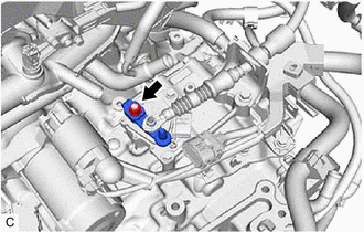
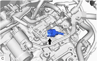
| (a) Disconnect the park/neutral position switch assembly connector. |
|
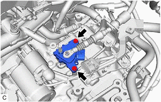
| (b) Remove the nut, washer and transmission control shaft lever from the manual valve lever shaft sub-assembly. |
|
| (c) Loosen the 2 bolts of the park/neutral position switch assembly. |
|
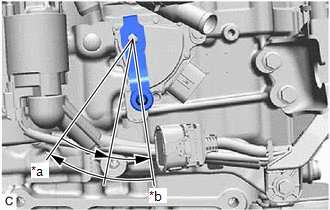
| (d) Align the protrusion with the neutral basic line. |
|
(e) Hold the park/neutral position switch assembly in position and tighten the 2 bolts.
Torque:
5.4 N·m {55 kgf·cm, 48 in·lbf}
(f) Install the transmission control shaft lever to the manual valve lever shaft sub-assembly with the washer and nut.
Torque:
12.7 N·m {130 kgf·cm, 9 ft·lbf}
(g) Connect the park/neutral position switch assembly connector.
4. CONNECT TRANSMISSION CONTROL CABLE ASSEMBLY
Click here
5. INSPECT PARK/NEUTRAL POSITION SWITCH ASSEMBLY
Click here
COMPONENTS
ILLUSTRATION
|
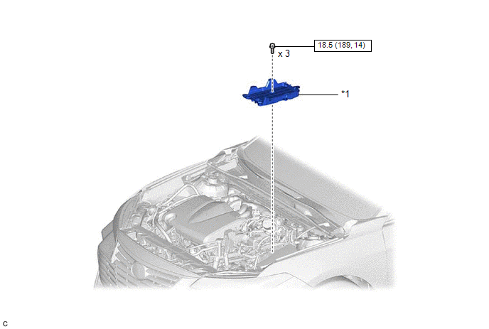
*1 | BATTERY CLAMP SUB-ASSEMBLY |
- | - |
 |
N*m (kgf*cm, ft.*lbf): Specified torque |
- | - |
ILLUSTRATION
|
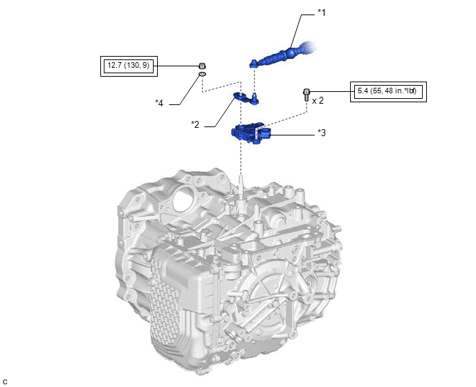
*1 | TRANSMISSION CONTROL CABLE ASSEMBLY |
*2 | TRANSMISSION CONTROL SHAFT LEVER |
|
*3 | PARK/NEUTRAL POSITION SWITCH ASSEMBLY |
*4 | WASHER |
 |
Tightening torque for "Major areas involving basic vehicle performance such as moving/turning/stopping": N*m (kgf*cm, ft.*lbf) |
- | - |
INSPECTION
PROCEDURE
1. INSPECT PARK/NEUTRAL POSITION SWITCH ASSEMBLY
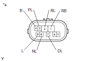
| (a) Measure the resistance according to the value(s) in the table below when the transmission control shaft lever is moved to each position. Standard Resistance:
If the result is not as specified, replace the park/neutral position switch assembly. |
|
INSTALLATION
PROCEDURE
1. INSTALL PARK/NEUTRAL POSITION SWITCH ASSEMBLY
(a) Temporarily install the park/neutral position switch assembly to the automatic transaxle case sub-assembly with the 2 bolts.
NOTICE:
Before installing the park/neutral position switch assembly, remove any dirt or rust on the manual valve lever shaft sub-assembly. Be sure to install the park/neutral position switch assembly straight along the manual valve lever shaft sub-assembly while being careful not to deform the plate spring that supports the manual valve lever shaft sub-assembly. If the plate spring is deformed, the park/neutral position switch assembly cannot be installed correctly.
(b) Temporarily install the transmission control shaft lever to the park/neutral position switch assembly.
| (c) Turn the transmission control shaft lever clockwise until it stops, then turn it counterclockwise 2 notches. |
|
(d) Remove the transmission control shaft lever from the park/neutral position switch assembly.
| (e) Align the protrusion with the neutral basic line. |
|
(f) Hold the park/neutral position switch assembly in that position and tighten the 2 bolts.
Torque:
5.4 N·m {55 kgf·cm, 48 in·lbf}
(g) Install the transmission control shaft lever to the manual valve lever shaft sub-assembly with the washer and nut.
Torque:
12.7 N·m {130 kgf·cm, 9 ft·lbf}
(h) Connect the park/neutral position switch assembly connector.
2. CONNECT TRANSMISSION CONTROL CABLE ASSEMBLY
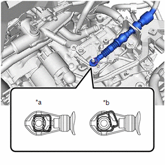
| (a) Connect the transmission control cable assembly to the transmission control shaft lever as shown in the illustration. NOTICE: Before connecting the transmission control cable assembly, check that the park/neutral position switch assembly and shift lever are in N. |
|
3. INSTALL BATTERY CLAMP SUB-ASSEMBLY
Click here

4. INSTALL ECM
Click here
5. INSTALL BATTERY
Click here
6. INSPECT PARK/NEUTRAL POSITION SWITCH ASSEMBLY OPERATION
Click here
7. INSPECT SHIFT LEVER POSITION
Click here
8. ADJUST SHIFT LEVER POSITION
Click here
ON-VEHICLE INSPECTION
PROCEDURE
1. SECURE VEHICLE
(a) Fully apply the parking brake and chock a wheel.
CAUTION:

2. INSPECT PARK/NEUTRAL POSITION SWITCH ASSEMBLY OPERATION
(a) Turn the engine switch on (IG).
(b) Depress the brake pedal and check that the engine can be started when the shift lever is in N or P, but cannot be started in any other position.
(c) Check that the back-up lights come on when the shift lever is moved to R, but do not come on with the shift lever in any other position.
If the operation is not as specified, check the park/neutral position switch assembly.
Click here 
REMOVAL
CAUTION / NOTICE / HINT
The necessary procedures (adjustment, calibration, initialization or registration) that must be performed after parts are removed and installed, or replaced during park/neutral position switch assembly removal/installation are shown below.
Necessary Procedures After Parts Removed/Installed/Replaced|
Replaced Part or Performed Procedure |
Necessary Procedure | Effect/Inoperative Function when Necessary Procedure not Performed |
Link |
|---|---|---|---|
|
Battery terminal is disconnected/reconnected |
Perform steering sensor zero point calibration |
Lane Departure Alert System (w/ Steering Control) |
|
|
Pre-collision System | |||
|
Intelligent Clearance Sonar System*1 | |||
|
Lighting System (for Gasoline Model with Cornering Light) | |||
|
Memorize steering angle neutral point |
Parking Assist Monitor System |
| |
|
Panoramic View Monitor System |
| ||
|
Replacement of ECM | Vehicle Identification Number (VIN) registration |
MIL comes on |
|
|
ECU communication ID registration (Immobiliser system) |
Engine start function |
| |
|
Replacement of ECM (If transaxle compensation code read from ECM) |
|
|
|
|
Replacement of ECM (If transaxle compensation code not read from ECM) |
| ||
| Replacement of ECM |
Code registration (Smart key System (for Start Function)) |
|
|
Click here 
NOTICE:
Before removing the park/neutral position switch assembly, check that the shift lever is in N.
PROCEDURE
1. SECURE VEHICLE
(a) Fully apply the parking brake and chock a wheel.
CAUTION:

2. REMOVE BATTERY
Click here
3. REMOVE ECM
Click here
4. REMOVE BATTERY CLAMP SUB-ASSEMBLY
Click here
5. DISCONNECT TRANSMISSION CONTROL CABLE ASSEMBLY
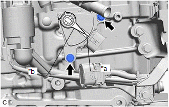
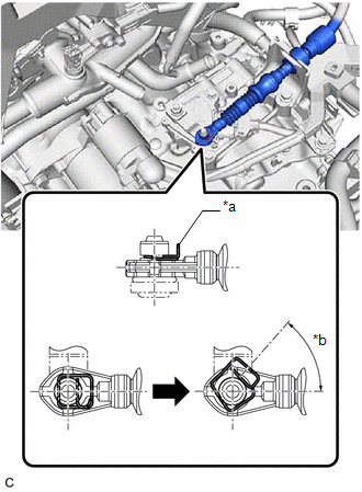
| (a) While disengaging the clip as shown in the illustration, disconnect the transmission control cable assembly from the transmission control shaft lever together with the clip. |
|
6. REMOVE PARK/NEUTRAL POSITION SWITCH ASSEMBLY
| (a) Disconnect the park/neutral position switch assembly connector. |
|
| (b) Remove the nut, washer and transmission control shaft lever from the manual valve lever shaft sub-assembly. |
|
| (c) Remove the 2 bolts and park/neutral position switch assembly from the automatic transaxle case sub-assembly. NOTICE: Before removing the park/neutral position switch assembly, remove any dirt or rust on the installation portion of the manual valve lever shaft sub-assembly. Be sure to remove the park/neutral position switch assembly straight along the manual valve lever shaft sub-assembly while being careful not to deform the plate spring that supports the manual valve lever shaft sub-assembly. If the plate spring is deformed, the park/neutral position switch assembly cannot be reinstalled correctly. |
|
Toyota Avalon (XX50) 2019-2022 Service & Repair Manual > Can Communication System(for Gasoline Model): Diagnostic Trouble Code Chart. Door Mirror ECU LH Communication Stop Mode. Door Mirror ECU RH Communication Stop Mode
Diagnostic Trouble Code Chart DIAGNOSTIC TROUBLE CODE CHART Diagnostic Trouble Code Chart DTC No. Detection Item Trouble Area Link B1003 ECU Malfunction Central gateway ECU (network gateway ECU) Door Mirror ECU LH Communication Stop Mode DESCRIPTION Detection Item Symptom Trouble Area Door Mirror EC ...