COMPONENTS
ILLUSTRATION
|
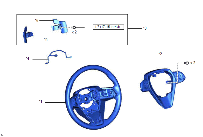
*1 | STEERING WHEEL ASSEMBLY |
*2 | STEERING PAD SWITCH ASSEMBLY |
|
*3 | SHIFT PADDLE SWITCH (TRANSMISSION SHIFT SWITCH ASSEMBLY) |
*4 | NO. 1 SWITCH WIRE |
|
*5 | NO. 1 TRANSMISSION SHIFT SWITCH ASSEMBLY |
*6 | NO. 2 TRANSMISSION SHIFT SWITCH ASSEMBLY |
 |
N*m (kgf*cm, ft.*lbf): Specified torque |
● | Non-reusable part |
|
★ | Precoated part |
- | - |
INSPECTION
PROCEDURE
1. INSPECT SHIFT PADDLE SWITCH (TRANSMISSION SHIFT SWITCH ASSEMBLY)
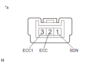
(a) No. 1 transmission shift switch assembly:
| (1) Measure the resistance according to the value(s) in the table below. Standard Resistance:
If the result is not as specified, replace the No. 1 transmission shift switch assembly. |
|
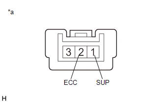
(b) No. 2 transmission shift switch assembly:
| (1) Measure the resistance according to the value(s) in the table below. Standard Resistance:
If the result is not as specified, replace the No. 2 transmission shift switch assembly. |
|
INSTALLATION
PROCEDURE
1. INSTALL NO. 1 SWITCH WIRE
HINT:
Perform this procedure only when replacement of the No. 1 switch wire is necessary.
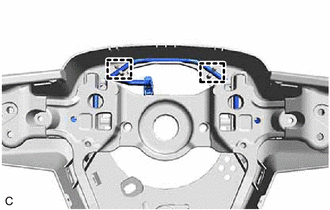
(a) Engage the 2 guides to install the No. 1 switch wire to the steering wheel assembly.
2. INSTALL SHIFT PADDLE SWITCH (TRANSMISSION SHIFT SWITCH ASSEMBLY)
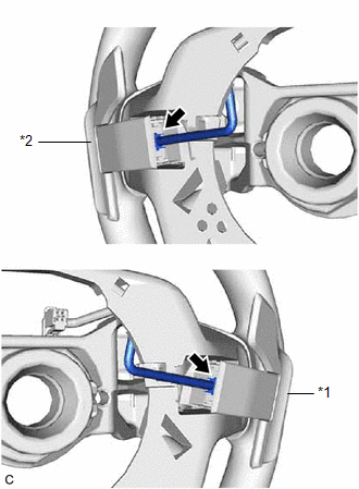
(a) Connect the No. 1 transmission shift switch assembly connector and No. 2 transmission shift switch assembly connector to install the No. 1 transmission shift switch assembly and No. 2 transmission shift switch assembly to the No. 1 switch wire.
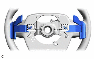
(b) Engage the 2 clamps.
(c) Engage the 4 claws to install the shift paddle switch (transmission shift switch assembly) to the steering wheel assembly.
(d) Install 2 new screws.
Torque:
1.7 N·m {17 kgf·cm, 15 in·lbf}
3. INSTALL STEERING PAD SWITCH ASSEMBLY
Click here

4. INSTALL STEERING WHEEL ASSEMBLY
Click here
REMOVAL
CAUTION / NOTICE / HINT
The necessary procedures (adjustment, calibration, initialization or registration) that must be performed after parts are removed and installed, or replaced during shift paddle switch (transmission shift switch assembly) removal/installation are shown below.
Necessary Procedures After Parts Removed/Installed/Replaced|
Replaced Part or Performed Procedure |
Necessary Procedure | Effect/Inoperative Function when Necessary Procedure not Performed |
Link |
|---|---|---|---|
|
*: When performing learning using the Techstream.
Click here | |||
|
Battery terminal is disconnected/reconnected |
Perform steering sensor zero point calibration |
Lane Departure Alert System (w/ Steering Control) |
|
|
Pre-collision System | |||
|
Intelligent Clearance Sonar System* | |||
|
Lighting System (for Gasoline Model with Cornering Light) | |||
|
Memorize steering angle neutral point |
Parking Assist Monitor System |
| |
|
Panoramic View Monitor System |
| ||
NOTICE:
PROCEDURE
1. REMOVE STEERING WHEEL ASSEMBLY
Click here 
2. REMOVE STEERING PAD SWITCH ASSEMBLY
Click here
3. REMOVE SHIFT PADDLE SWITCH (TRANSMISSION SHIFT SWITCH ASSEMBLY)
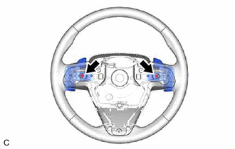
| (a) Remove the 2 screws. |
|
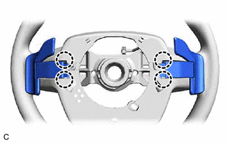
| (b) Disengage the 4 claws. |
|
| (c) Disengage the 2 clamps to disconnect the shift paddle switch (transmission shift switch assemby) from the steering wheel assembly. |
|
| (d) Disconnect the No. 1 transmission shift switch assembly connector and No. 2 transmission shift switch assembly connector to remove the No. 1 transmission shift switch assembly and No. 2 transmission shift switch assembly from the No. 1 switch wire. |
|
4. REMOVE NO. 1 SWITCH WIRE
HINT:
Perform this procedure only when replacement of the No. 1 switch wire is necessary.
| (a) Disengage the 2 guides and remove the No. 1 switch wire from the steering wheel assembly. |
|
Toyota Avalon (XX50) 2019-2022 Service & Repair Manual > Motor Generator Control System: DC/DC Converter Temperature Sensor "A" Circuit Short to Ground (P0C3811,P0C3815,P0C3D11,P0C3D15). Drive Motor "A" Position Sensor Circuit "A" Circuit Open (P0C5013,P0C501F,P0C5A13,P0C5A1F). Generator
DC/DC Converter Temperature Sensor "A" Circuit Short to Ground (P0C3811,P0C3815,P0C3D11,P0C3D15) DESCRIPTION The motor generator control ECU (MG ECU) located in the inverter with converter assembly detects the temperature of the boost converter using the temperature sensor built into the boost conve ...