ADJUSTMENT
PROCEDURE
1. SECURE VEHICLE
(a) Fully apply the parking brake and chock a wheel.
CAUTION:
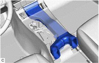
2. REMOVE CONSOLE BOX ASSEMBLY
Click here 
3. ADJUST SHIFT LEVER POSITION
NOTICE:
Before adjusting the transmission control cable assembly, check that the park/neutral position switch assembly and shift lever are in N.
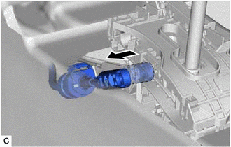
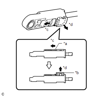
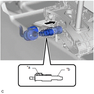
| (a) Disconnect the transmission control cable assembly from the transmission floor shift assembly. |
|
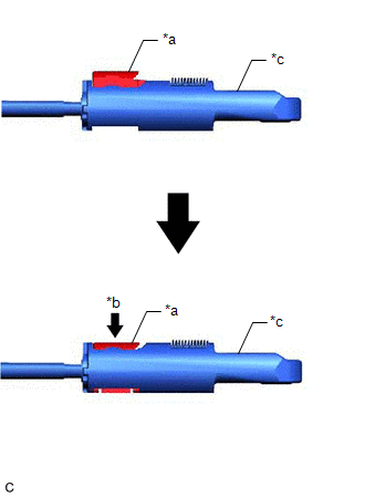
| (b) Slide the slider of the transmission control cable assembly in the direction indicated by the arrow in the illustration and pull the lock piece outward. |
|
| (c) Connect the transmission control cable assembly to the transmission floor shift assembly. NOTICE:
|
|
| (d) Push the lock piece into the adjuster case. NOTICE:
|
|
(e) After adjusting the shift lever position, check the position and operation of the shift lever. If there is a problem, adjust the shift lever position again.
4. INSTALL CONSOLE BOX ASSEMBLY
Click here
COMPONENTS
ILLUSTRATION
|
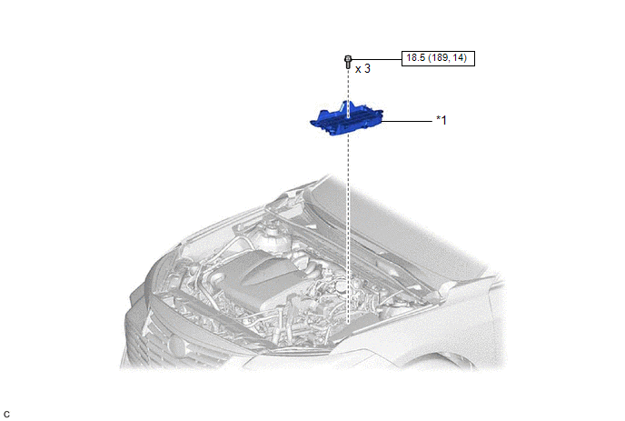
*1 | BATTERY CLAMP SUB-ASSEMBLY |
- | - |
 |
N*m (kgf*cm, ft.*lbf): Specified torque |
- | - |
ILLUSTRATION
|
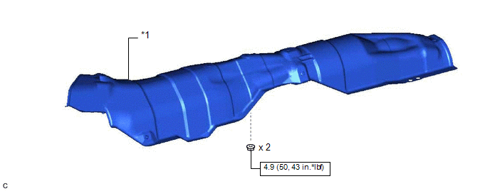
*1 | FRONT LOWER NO. 1 FLOOR HEAT INSULATOR |
- | - |
|
|
N*m (kgf*cm, ft.*lbf): Specified torque |
- | - |
ILLUSTRATION
|
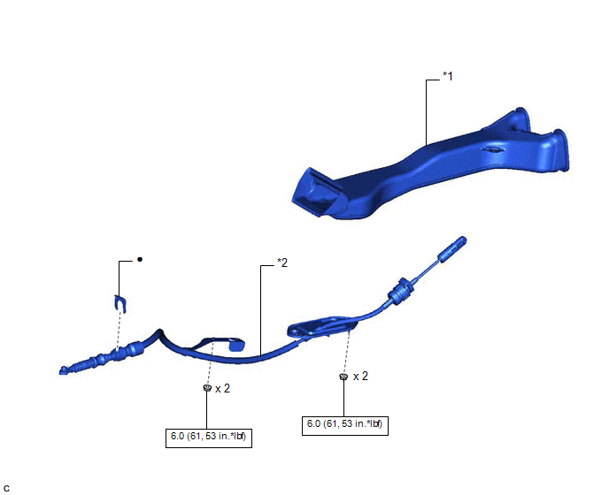
*1 | NO. 1 CONSOLE BOX DUCT |
*2 | TRANSMISSION CONTROL CABLE ASSEMBLY |
|
|
N*m (kgf*cm, ft.*lbf): Specified torque |
● | Non-reusable part |
INSTALLATION
PROCEDURE
1. INSTALL TRANSMISSION CONTROL CABLE ASSEMBLY
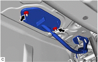
(a) Pass the transmission control cable assembly into the vehicle and install the transmission control cable assembly to the vehicle body with the 2 nuts.
Torque:
6.0 N·m {61 kgf·cm, 53 in·lbf}
(b) Connect the transmission control cable assembly to the vehicle body with the 2 nuts.
Torque:
6.0 N·m {61 kgf·cm, 53 in·lbf}
(c) Connect the transmission control cable assembly to the No. 1 transmission control cable bracket with a new clip.
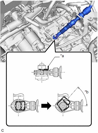
| (d) Connect the transmission control cable assembly to the transmission control shaft lever as shown in the illustration. NOTICE: Before installing the transmission control cable assembly, check that the park/neutral position switch assembly and shift lever are in N. |
|
2. INSTALL NO. 1 CONSOLE BOX DUCT
(a) Install the No. 1 console box duct.
3. INSTALL TRANSMISSION FLOOR SHIFT ASSEMBLY
Click here

4. INSTALL FRONT LOWER NO. 1 FLOOR HEAT INSULATOR
(a) Install the front lower No. 1 floor heat insulator to the vehicle body with the 2 nuts.
Torque:
4.9 N·m {50 kgf·cm, 43 in·lbf}
5. INSTALL FRONT EXHAUST PIPE ASSEMBLY
Click here
6. INSTALL BATTERY CLAMP SUB-ASSEMBLY
Click here
7. INSTALL ECM
Click here
8. INSTALL BATTERY
Click here
9. INSPECT SHIFT LEVER POSITION
Click here
10. ADJUST SHIFT LEVER POSITION
Click here
REMOVAL
CAUTION / NOTICE / HINT
The necessary procedures (adjustment, calibration, initialization or registration) that must be performed after parts are removed and installed, or replaced during transmission control cable assembly removal/installation are shown below.
Necessary Procedures After Parts Removed/Installed/Replaced|
Replaced Part or Performed Procedure |
Necessary Procedure | Effect/Inoperative Function when Necessary Procedure not Performed |
Link |
|---|---|---|---|
|
Battery terminal is disconnected/reconnected |
Perform steering sensor zero point calibration |
Lane Departure Alert System (w/ Steering Control) |
|
|
Pre-collision System | |||
|
Intelligent Clearance Sonar System*1 | |||
|
Lighting System (for Gasoline Model with Cornering Light) | |||
|
Memorize steering angle neutral point |
Parking Assist Monitor System |
| |
|
Panoramic View Monitor System |
| ||
|
Replacement of ECM | Vehicle Identification Number (VIN) registration |
MIL comes on |
|
|
ECU communication ID registration (Immobiliser system) |
Engine start function |
| |
|
Replacement of ECM (If transaxle compensation code read from ECM) |
|
|
|
|
Replacement of ECM (If transaxle compensation code not read from ECM) |
| ||
| Replacement of ECM |
Code registration (Smart key System (for Start Function)) |
|
|
Click here 
PROCEDURE
1. REMOVE BATTERY
Click here
2. REMOVE ECM
Click here
3. REMOVE BATTERY CLAMP SUB-ASSEMBLY
Click here
4. REMOVE FRONT EXHAUST PIPE ASSEMBLY
Click here
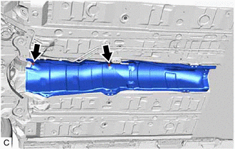
5. REMOVE FRONT LOWER NO. 1 FLOOR HEAT INSULATOR
| (a) Remove the 2 nuts and front lower No. 1 floor heat insulator from the vehicle body. |
|
6. REMOVE TRANSMISSION FLOOR SHIFT ASSEMBLY
Click here
7. REMOVE NO. 1 CONSOLE BOX DUCT
| (a) Remove the No. 1 console box duct. |
|
8. REMOVE TRANSMISSION CONTROL CABLE ASSEMBLY
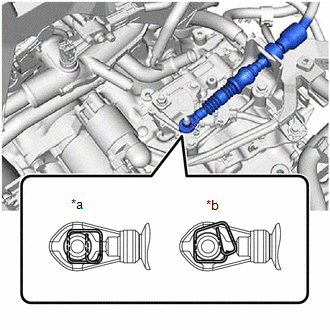
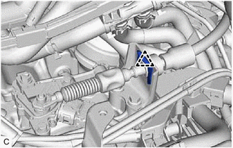
| (a) While disengaging the clip as shown in the illustration, disconnect the transmission control cable assembly from the transmission control shaft lever together with the clip. |
|
| (b) Remove the clip and disconnect the transmission control cable assembly from the No. 1 transmission control cable bracket. |
|
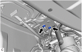
| (c) Remove the 2 nuts and disconnect the transmission control cable assembly from the vehicle body. |
|
| (d) Remove the 2 nuts and then remove the transmission control cable assembly from the vehicle body. |
|
Toyota Avalon (XX50) 2019-2022 Service & Repair Manual > Electronically Controlled Brake System(for Gasoline Model): Problem Symptoms Table. Slip Indicator Light does not Come ON. Slip Indicator Light Remains ON
Problem Symptoms Table PROBLEM SYMPTOMS TABLE If there are no DTCs output and the problem still occurs, check the suspected areas for each problem symptom in the order given in the following table and proceed to the relevant troubleshooting page. NOTICE: When replacing the skid control ECU (brake ac ...