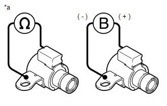
INSPECTION PROCEDURE 1. INSPECT SOLENOID (SL) VALVE
(b) Connect a positive (+) lead from the battery to the terminal of the solenoid (SL) valve connector and a negative (-) lead to the solenoid (SL) valve body, and check that the solenoid (SL) valve moves and makes an operating sound. NOTICE: When using battery voltage during the inspection, do not bring the positive (+) and negative (-) tester probes too close to each other as a short circuit may occur. OK: The solenoid (SL) valve moves and makes an operating sound. If the result is not as specified, replace the solenoid (SL) valve. 2. INSPECT SOLENOID (SLT) VALVE
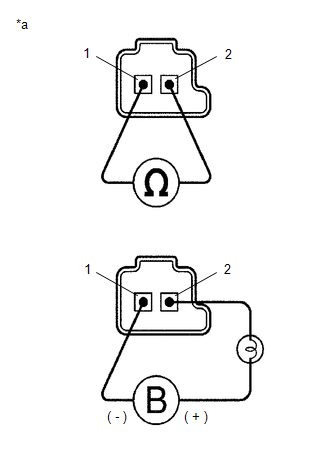
(b) Connect a positive (+) lead from the battery with a 21 W bulb to terminal 2 and a negative (-) lead to terminal 1 of the solenoid (SLT) valve connector, and check that the solenoid (SLT) valve moves and makes an operating sound. NOTICE: When using battery voltage during the inspection, do not bring the positive (+) and negative (-) tester probes too close to each other as a short circuit may occur. OK: The solenoid (SLT) valve moves and makes an operating sound. If the result is not as specified, replace the solenoid (SLT) valve. 3. INSPECT SOLENOID (SLU) VALVE HINT: Refer to Inspect Solenoid (SLT) Valve. 4. INSPECT SOLENOID (SL1) VALVE HINT: Refer to Inspect Solenoid (SLT) Valve. 5. INSPECT SOLENOID (SL2) VALVE HINT: Refer to Inspect Solenoid (SLT) Valve. 6. INSPECT SOLENOID (SL3) VALVE HINT: Refer to Inspect Solenoid (SLT) Valve. 7. INSPECT SOLENOID (SL4) VALVE HINT: Refer to Inspect Solenoid (SLT) Valve. 8. INSPECT SOLENOID (SL5) VALVE HINT: Refer to Inspect Solenoid (SLT) Valve. 9. INSPECT SOLENOID (SL6) VALVE HINT: Refer to Inspect Solenoid (SLT) Valve. |
Toyota Avalon (XX50) 2019-2022 Service & Repair Manual > Can Communication System(for Gasoline Model): Radio Receiver Assembly Communication Stop Mode
DESCRIPTION Detection Item Symptom Trouble Area Radio Receiver Assembly Communication Stop Mode Any of the following conditions are met: Communication stop for "Display and Navigation (AVN)" is indicated on the "Communication Bus Check" screen of the Techstream. Click here Communication stop history ...