COMPONENTS
ILLUSTRATION
|
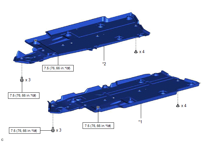
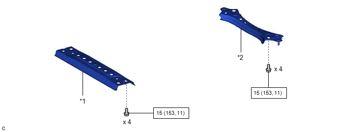
*1 | FRONT FLOOR COVER LH |
*2 | FRONT FLOOR COVER RH |
 |
N*m (kgf*cm, ft.*lbf): Specified torque |
- | - |
ILLUSTRATION
|
*1 | CENTER FLOOR CROSSMEMBER BRACE |
*2 | FRONT CENTER FLOOR BRACE |
|
|
N*m (kgf*cm, ft.*lbf): Specified torque |
- | - |
ILLUSTRATION
|
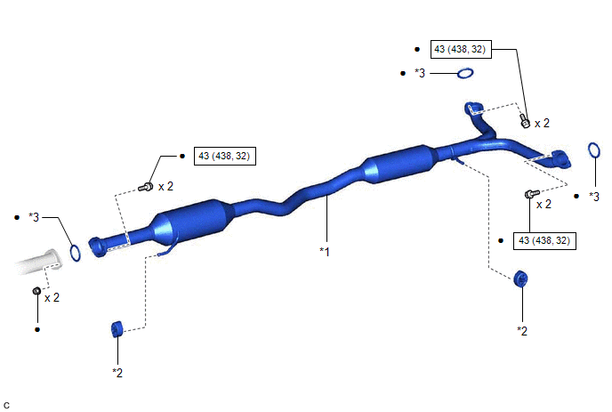
*1 | CENTER EXHAUST PIPE ASSEMBLY |
*2 | EXHAUST PIPE SUPPORT |
|
*3 | GASKET |
- | - |
|
|
N*m (kgf*cm, ft.*lbf): Specified torque |
● | Non-reusable part |
ILLUSTRATION
|
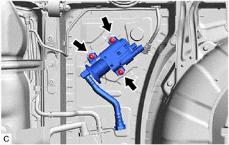
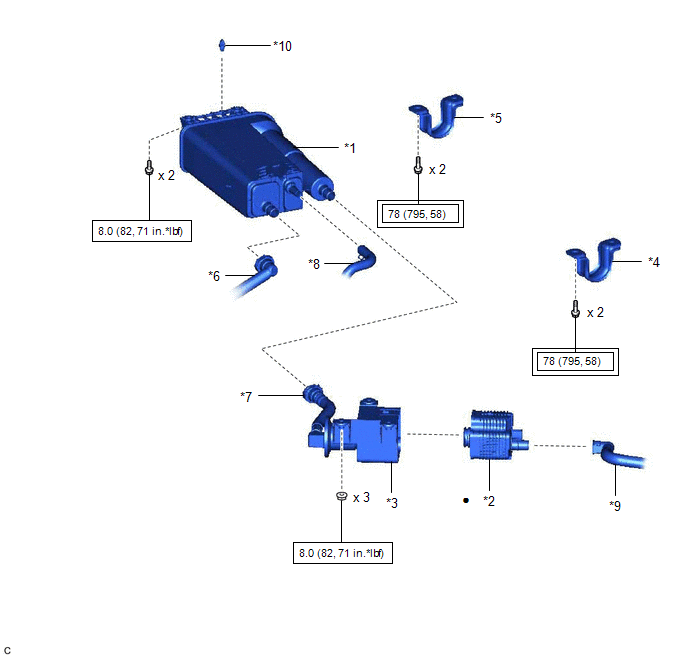
*1 | CANISTER (CHARCOAL CANISTER ASSEMBLY) |
*2 | LEAK DETECTION PUMP SUB-ASSEMBLY |
|
*3 | NO. 2 CHARCOAL CANISTER SUB-ASSEMBLY |
*4 | REAR NO. 1 STABILIZER BAR BRACKET LH |
|
*5 | REAR NO. 1 STABILIZER BAR BRACKET RH |
*6 | FUEL TANK VENT HOSE |
|
*7 | VENT LINE HOSE |
*8 | PURGE LINE HOSE |
|
*9 | AIR LINE TUBE |
*10 | CLIP |
 |
Tightening torque for "Major areas involving basic vehicle performance such as moving/turning/stopping": N*m (kgf*cm, ft.*lbf) |
|
N*m (kgf*cm, ft.*lbf): Specified torque |
|
● | Non-reusable part |
- | - |
INSPECTION
PROCEDURE
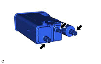
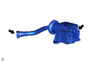
1. INSPECT CANISTER (CHARCOAL CANISTER ASSEMBLY)
| (a) Visually check the canister (charcoal canister assembly). (1) Visually check the canister (charcoal canister assembly) for cracks or damage. If cracks or damage are found, replace the canister (charcoal canister assembly). |
|
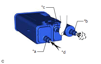
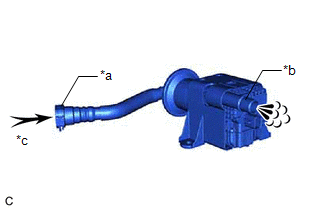
(b) Check canister (charcoal canister assembly) operation.
| (1) With the purge line port closed, blow 0.5 kPa (0.005 kgf/cm2, 0.1 psi) of air into the vent line port, and check that air flows from the air line port. If the result is not as specified, replace the canister (charcoal canister assembly). |
|
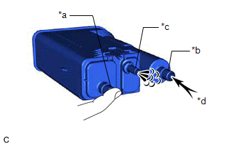
| (2) With the vent line port closed, blow 0.5 kPa (0.005 kgf/cm2, 0.1 psi) of air into the air line port, and check that air flows from the purge line port. If the result is not as specified, replace the canister (charcoal canister assembly). |
|
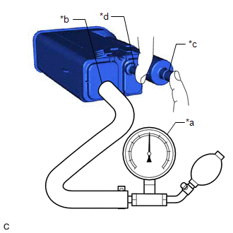
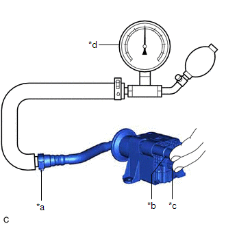
(c) Check for air leaks.
|
(1) Connect a pressure gauge to the vent line port. |
|
(2) With the purge line port and air line port closed, apply 20 kPa (150 mmHg, 5.91 in. Hg) of pressurized air into the vent line port, then confirm that pressure is maintained for 1 minute.
If the result is not as specified, replace the canister (charcoal canister assembly).
2. INSPECT NO. 2 CHARCOAL CANISTER SUB-ASSEMBLY
| (a) Visually check the No. 2 charcoal canister sub-assembly. (1) Visually check the No. 2 charcoal canister sub-assembly for cracks or damage. If cracks or damage are found, replace the No. 2 charcoal canister sub-assembly. |
|
(b) Check No. 2 charcoal canister sub-assembly operation.
| (1) Blow 0.5 kPa (0.005 kgf/cm2, 0.1 psi) of air into the port A, and check that air flows from the port B. If the result is not as specified, replace the No. 2 charcoal canister sub-assembly. |
|
(c) Check for air leaks.
|
(1) Connect a pressure gauge to the port A. |
|
(2) With the port B and leak detection pump sub-assembly connector closed, apply 20 kPa (150 mmHg, 5.91 in. Hg) of pressurized air into the port A, then confirm that pressure is maintained for 1 minute.
If the result is not as specified, replace the No. 2 charcoal canister sub-assembly.
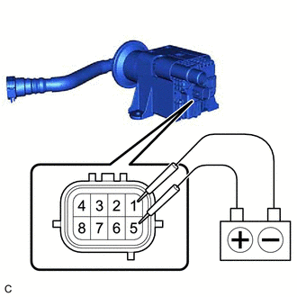
(d) Check the leak detection pump sub-assembly.
| (1) Connect a positive (+) lead from the battery to terminal 5 and a negative (-) lead to terminal 1. |
|
(2) Check that a clicking sound is heard from the leak detection pump sub-assembly.
If the result is not as specified, replace the leak detection pump sub-assembly.
INSTALLATION
PROCEDURE
1. INSTALL LEAK DETECTION PUMP SUB-ASSEMBLY
HINT:
Only perform this procedure when replacement of the leak detection pump sub-assembly is necessary.
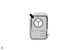
| (a) Engage the 2 claws to install a new leak detection pump sub-assembly to the No. 2 charcoal canister sub-assembly. NOTICE:
|
|
2. INSTALL NO. 2 CHARCOAL CANISTER SUB-ASSEMBLY
(a) Remove the rear suspension member sub-assembly.
Click here
(b) Install the No. 2 charcoal canister sub-assembly to the vehicle body with the 3 nuts.
Torque:
8.0 N·m {82 kgf·cm, 71 in·lbf}
(c) Connect the leak detection pump sub-assembly connector.
(d) Push in the air line tube to the pipe (leak detection pump sub-assembly) until the air line tube makes a "click" sound.
NOTICE:
(e) Install the rear suspension member sub-assembly.
Click here

3. INSTALL CANISTER (CHARCOAL CANISTER ASSEMBLY)
(a) Install the clip to the vehicle body.
| (b) Engage the claw to install the canister (charcoal canister assembly) to the vehicle body as shown in the illustration. |
|
(c) Engage the clip to the canister (charcoal canister assembly).
(d) Install the 2 bolts.
Torque:
8.0 N·m {82 kgf·cm, 71 in·lbf}
(e) Connect the purge line hose to the canister (charcoal canister assembly) and slide the clip to secure it.
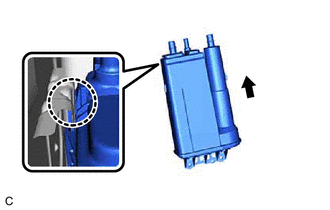
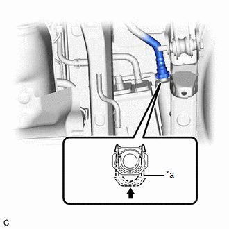
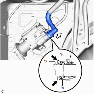
(f) Push the vent line hose onto the canister (charcoal canister assembly) and push in the retainer to engage the lock claws.
NOTICE:
|
*a | Retainer |
 |
Push in |
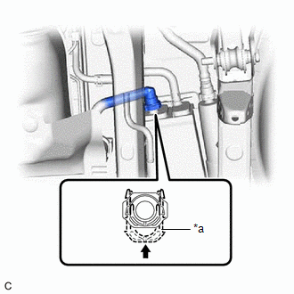
(g) Push the fuel tank vent hose onto the canister (charcoal canister assembly) and push in the retainer to engage the lock claws.
NOTICE:
|
*a | Retainer |
|
|
Push in |
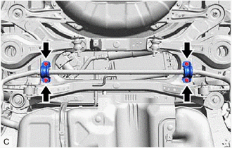
4. INSTALL REAR STABILIZER BAR
(a) Install the rear stabilizer bar with the rear No. 1 stabilizer bar bracket LH, rear No. 1 stabilizer bar bracket RH and 4 bolts.
Torque:
78 N·m {795 kgf·cm, 58 ft·lbf}
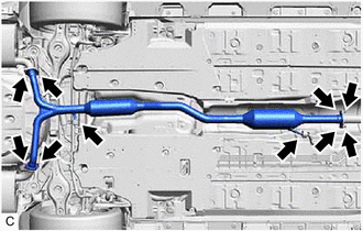
5. INSTALL CENTER EXHAUST PIPE ASSEMBLY
(a) Install 3 new gaskets to the front exhaust pipe assembly (TWC: Rear Catalyst) and center exhaust pipe assembly.
(b) Connect the center exhaust pipe assembly to the 2 exhaust pipe supports.
(c) Install the center exhaust pipe assembly to the front exhaust pipe assembly (TWC: Rear Catalyst), tail exhaust pipe assembly and tail exhaust pipe assembly LH with 6 new bolts and 2 new nuts.
Torque:
43 N·m {438 kgf·cm, 32 ft·lbf}
6. INSTALL CENTER FLOOR CROSSMEMBER BRACE
Click here
7. INSTALL FRONT CENTER FLOOR BRACE
Click here
8. INSTALL FRONT FLOOR COVER LH
Click here
9. INSTALL FRONT FLOOR COVER RH
Click here
10. INSPECT FOR EXHAUST GAS LEAK
Click here
REMOVAL
CAUTION / NOTICE / HINT
The necessary procedures (adjustment, calibration, initialization or registration) that must be performed after parts are removed and installed, or replaced during canister (charcoal canister assembly) removal/installation are shown below.
Necessary Procedures After Parts Removed/Installed/Replaced|
Replaced Part or Performed Procedure |
Necessary Procedure | Effect/Inoperative Function when Necessary Procedure not Performed |
Link |
|---|---|---|---|
| Gas leak from exhaust system is repaired |
Inspection After Repair |
|
|
PROCEDURE
1. REMOVE FRONT FLOOR COVER LH
Click here

2. REMOVE FRONT FLOOR COVER RH
Click here
3. REMOVE FRONT CENTER FLOOR BRACE
Click here
4. REMOVE CENTER FLOOR CROSSMEMBER BRACE
Click here
5. REMOVE CENTER EXHAUST PIPE ASSEMBLY
CAUTION:
To prevent burns, do not touch the engine, exhaust pipe or other high temperature components while the engine is hot.
| (a) Remove the 6 bolts, 2 nuts and disconnect the center exhaust pipe assembly from the front exhaust pipe assembly (TWC: Rear Catalyst), tail exhaust pipe assembly and tail exhaust pipe assembly LH. |
|
(b) Remove the center exhaust pipe assembly from the 2 exhaust pipe supports.
(c) Remove the 3 gaskets from the center exhaust pipe assembly and front exhaust pipe assembly (TWC: Rear Catalyst).
6. SEPARATE REAR STABILIZER BAR
| (a) Remove the 4 bolts, rear No. 1 stabilizer bar bracket LH, rear No. 1 stabilizer bar bracket RH and separate the rear stabilizer bar. |
|
7. REMOVE CANISTER (CHARCOAL CANISTER ASSEMBLY)
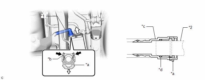
(a) Disconnect the fuel tank vent hose from the canister (charcoal canister assembly).
|
*1 | Fuel Tank Vent Hose |
*2 | Pipe (Canister (Charcoal Canister Assembly)) |
|
*a | Retainer |
*b | Tab |
|
*c | Tube Connector |
*d | O-ring |
 |
Pinch |
 |
Pull |
NOTICE:
HINT:
Do not remove the retainer.
(1) Pinch the tabs of the retainer to disengage the lock claws and pull it down.
(2) Pull off the fuel tank vent hose.
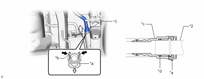
(b) Disconnect the vent line hose from the canister (charcoal canister assembly).
|
*1 | Vent Line Hose |
*2 | Pipe (Canister (Charcoal Canister Assembly)) |
|
*a | Retainer |
*b | Tab |
|
*c | Tube Connector |
*d | O-ring |
|
|
Pinch |
|
Pull |
NOTICE:
HINT:
Do not remove the retainer.
(1) Pinch the tabs of the retainer to disengage the lock claws and pull it down.
(2) Pull off the vent line hose.
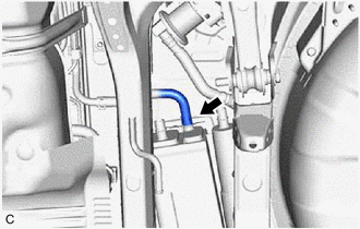
| (c) Slide the clip and disconnect the purge line hose from the canister (charcoal canister assembly). |
|
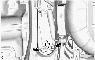
(d) Remove the 2 bolts.
|
| Bolt |
|
|
Clip |
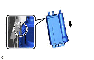
(e) Disengage the clip from the canister (charcoal canister assembly).
| (f) Disengage the claw and remove the canister (charcoal canister assembly) from vehicle body as shown in the illustration. |
|
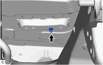
| (g) Remove the clip from the vehicle body. |
|
8. REMOVE NO. 2 CHARCOAL CANISTER SUB-ASSEMBLY
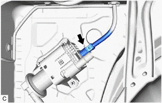
(a) Disconnect the air line tube from the leak detection pump sub-assembly.
|
*1 | Air Line Tube |
|
*2 | Pipe (Leak Detection Pump Sub-assembly) |
|
*a | Tube Connector |
|
*b | O-ring |
|
|
Pinch |
|
|
Pull off |
NOTICE:
(1) Push the air line tube firmly toward the leak detection pump sub-assembly.
(2) Pinch the tube connector as shown in the illustration.
(3) Pull off the air line tube from the pipe (leak detection pump sub-assembly).
| (b) Disconnect the leak detection pump sub-assembly connector. |
|
| (c) Remove the 3 nuts and No. 2 charcoal canister sub-assembly from the vehicle body. |
|
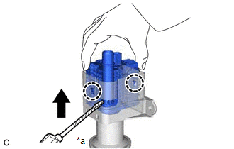
9. REMOVE LEAK DETECTION PUMP SUB-ASSEMBLY
HINT:
Only perform this procedure when replacement of the leak detection pump sub-assembly is necessary.
(a) Before removing the leak detection pump sub-assembly, clean the No. 2 charcoal canister sub-assembly by blowing air into it to ensure that the No. 2 charcoal canister sub-assembly is free of foreign matter.
NOTICE:
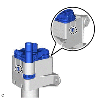
| (b) While disengaging the 2 claws as shown in the illustration, push the leak detection pump sub-assembly upwards using a screwdriver with its tip wrapped with protective tape to remove it. |
|
(c) Check if the No. 2 charcoal canister sub-assembly contains foreign matter such as mud or water.
| (1) Visually check that the inside of the No. 2 charcoal canister sub-assembly is free of foreign matter. |
|
(2) Hold the No. 2 charcoal canister sub-assembly upside down to make sure that it is free of foreign matter.
If the No. 2 charcoal canister sub-assembly contains foreign matter, replace it.
Toyota Avalon (XX50) 2019-2022 Service & Repair Manual > Sfi System: Knock Sensor 1 Bank 1 or Single Sensor Circuit Short to Battery or Open (P032515). Crankshaft Position Sensor "A" Circuit Short to Ground (P033511,P033515). Camshaft Position Sensor "A" Bank 1 or Sing
Knock Sensor 1 Bank 1 or Single Sensor Circuit Short to Battery or Open (P032515) DESCRIPTION Refer to DTC P032511. Click here HINT: When DTC P032515 is stored, the ECM enters fail-safe mode. During fail-safe mode, the ignition timing is delayed to its maximum retardation. Fail-safe mode continues u ...