Components
COMPONENTS
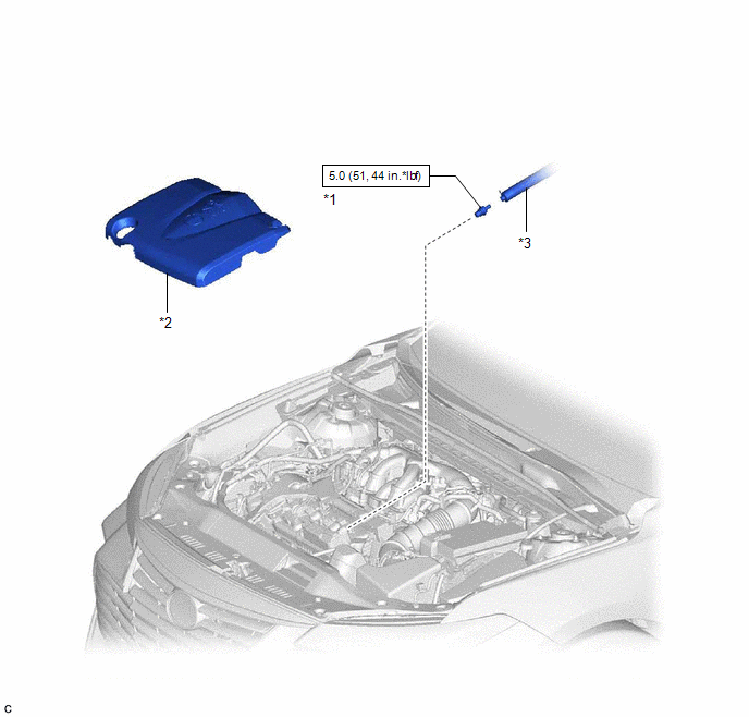
ILLUSTRATION
|
*1 | PCV VALVE (VENTILATION VALVE SUB-ASSEMBLY) |
*2 | V-BANK COVER SUB-ASSEMBLY |
|
*3 | VENTILATION HOSE |
- | - |
 |
N*m (kgf*cm, ft.*lbf): Specified torque |
- | - |
Inspection
INSPECTION
PROCEDURE
1. INSPECT PCV VALVE (VENTILATION VALVE SUB-ASSEMBLY)
(a) Install a hose to the PCV valve (ventilation valve sub-assembly).
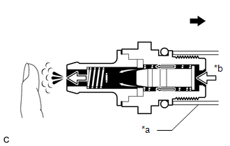
(b) Check PCV valve (ventilation valve sub-assembly) operation.
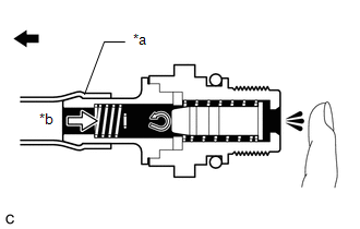
(1) Blow air into the cylinder head cover sub-assembly LH side, and check that air passes through easily.
|
*a | Hose |
|
*b | Air |
 |
Cylinder Head Cover Sub-assembly LH Side |
CAUTION:
Do not suck air through the valve.
Petroleum substances inside the valve are hazardous to your health.
If the result is not as specified, replace the PCV valve (ventilation valve sub-assembly).
(2) Blow air into the intake air surge tank assembly side, and check that air passes through with difficulty.
|
*a | Hose |
|
*b | Air |
|
|
Intake Air Surge Tank Assembly Side |
CAUTION:
Do not suck air through the valve.
Petroleum substances inside the valve are hazardous to your health.
If the result is not as specified, replace the PCV valve (ventilation valve sub-assembly).
(c) Remove the hose from the PCV valve (ventilation valve sub-assembly).
Installation
INSTALLATION
PROCEDURE
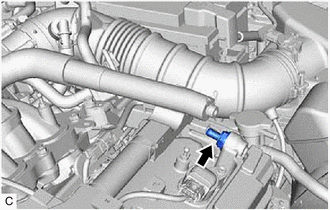
1. INSTALL PCV VALVE (VENTILATION VALVE SUB-ASSEMBLY)
(a) Apply a light coat of engine oil to the O-ring.
(b) Using a 22 mm deep socket wrench, install the PCV valve (ventilation valve sub-assembly) to the cylinder head cover sub-assembly LH.
Torque:
5.0 N·m {51 kgf·cm, 44 in·lbf}
NOTICE:
When reusing the PCV valve (ventilation valve sub-assembly), inspect the O-ring.
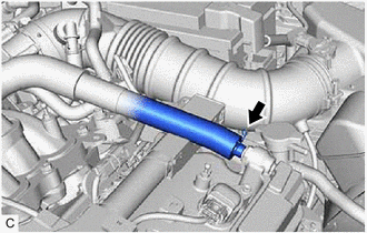
2. CONNECT VENTILATION HOSE
(a) Connect the ventilation hose to the PCV valve (ventilation valve sub-assembly) and slide the clip to secure it.
3. INSTALL V-BANK COVER SUB-ASSEMBLY
Click here

Removal
REMOVAL
PROCEDURE
1. REMOVE V-BANK COVER SUB-ASSEMBLY
Click here

2. DISCONNECT VENTILATION HOSE
| (a) Slide the clip and disconnect the ventilation hose from the PCV valve (ventilation valve sub-assembly). |
|
3. REMOVE PCV VALVE (VENTILATION VALVE SUB-ASSEMBLY)
| (a) Using a 22 mm deep socket wrench, remove the PCV valve (ventilation valve sub-assembly) from the cylinder head cover sub-assembly LH. |
|
Toyota Avalon (XX50) 2019-2022 Service & Repair Manual > Door Lock: Door Control Receiver
Components COMPONENTS ILLUSTRATION *A for HV Model - - *1 LUGGAGE TRIM SERVICE HOLE COVER - - ILLUSTRATION *A w/ Seat Heater System - - *1 SPARE WHEEL COVER ASSEMBLY - - ILLUSTRATION *A for Gasoline Model *B for HV Model *C w/ Seat Heater System - - *1 LUGGAGE COMPARTMENT INNER TRIM PAD *2 REAR CENT ...