COMPONENTS
ILLUSTRATION
|
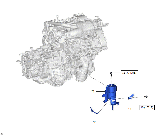
*1 | REAR ENGINE MOUNTING INSULATOR |
*2 | VACUUM HOSE |
|
*3 | WIRE HARNESS CLAMP BRACKET |
- | - |
 |
N*m (kgf*cm, ft.*lbf): Specified torque |
- | - |
INSTALLATION
PROCEDURE
1. INSTALL REAR ENGINE MOUNTING INSULATOR
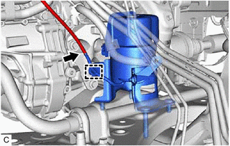
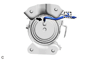
(a) Engage the clamp and install the vacuum hose to the rear engine mounting insulator.
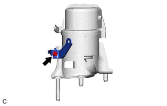
(b) Install the wire harness clamp bracket to the rear engine mounting insulator with the bolt.
Torque:
10 N·m {102 kgf·cm, 7 ft·lbf}
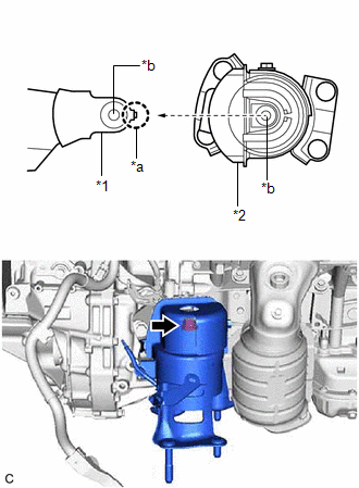
| (c) Align the hole of the rear engine mounting insulator with the protrusion of the rear engine mounting bracket, slide the rear engine mounting insulator onto the rear engine mounting bracket to align the holes and install the rear engine mounting insulator with the bolt. Torque: 72 N·m {734 kgf·cm, 53 ft·lbf} |
|
2. INSTALL FRONT FRAME ASSEMBLY
Click here

ON-VEHICLE INSPECTION
CAUTION / NOTICE / HINT
HINT:
Refer to Problem Symptoms Table.
Click here

PROCEDURE
1. REMOVE FRONT WHEEL OPENING EXTENSION PAD LH
Click here
2. REMOVE FRONT WHEEL OPENING EXTENSION PAD RH
Click here
3. REMOVE NO. 1 ENGINE UNDER COVER
Click here
4. REMOVE REAR ENGINE UNDER COVER LH
Click here
5. INSPECT REAR ENGINE MOUNTING INSULATOR
| (a) Disengage the clamp to separate the vacuum hose. |
|
(b) Disconnect the vacuum hose.
| (c) Using a vacuum pump, apply vacuum of 80 kPa (600 mmHg, 23.6 in.Hg) and wait for 1 minute. |
|
(d) Check that there is no change in the needle movement of the vacuum pump gauge.
OK:
Vacuum pressure holds.
(e) Check that there is no fluid leakage caused by a break in the diaphragm.
(f) Connect the vacuum hose.
(g) Engage the clamp to install the vacuum hose.
6. INSTALL REAR ENGINE UNDER COVER LH
Click here
7. INSTALL NO. 1 ENGINE UNDER COVER
Click here
8. INSTALL FRONT WHEEL OPENING EXTENSION PAD LH
Click here
9. INSTALL FRONT WHEEL OPENING EXTENSION PAD RH
Click here
REMOVAL
CAUTION / NOTICE / HINT
The necessary procedures (adjustment, calibration, initialization, or registration) that must be performed after parts are removed and installed, or replaced during rear engine mounting insulator removal/installation are shown below.
Necessary Procedure After Parts Removed/Installed/Replaced|
Replaced Part or Performed Procedure |
Necessary Procedure | Effect/Inoperative Function when Necessary Procedure not Performed |
Link |
|---|---|---|---|
|
Battery terminal is disconnected/reconnected |
Perform steering sensor zero point calibration |
Lane departure alert system (w/ Steering Control) |
|
|
Pre-collision system | |||
|
Intelligent Clearance Sonar System*1 | |||
|
Lighting System (for Gasoline Model with Cornering Light) | |||
|
Memorize steering angle neutral point |
Parking Assist Monitor System |
| |
|
Panoramic View Monitor System |
| ||
|
Replacement of ECM | Vehicle Identification Number (VIN) registration |
MIL comes on |
|
|
ECU communication ID registration (Immobiliser system) |
Engine start function |
| |
|
Gas leak from exhaust system is repaired |
Inspection after repair |
|
|
|
Replacement of ECM (If transaxle compensation code read from ECM) |
|
|
|
|
Replacement of ECM (If transaxle compensation code not read from ECM) |
| ||
| Replacement of ECM |
Code registration (Smart Key System (for Start Function)) |
|
|
|
Suspension, tires, etc. |
|
|
|
|
Rear television camera assembly optical axis adjustment (Back camera position setting) |
Parking Assist Monitor System |
| |
| Panoramic View Monitor System |
| |
|
Perform headlight ECU sub-assembly LH initialization |
Lighting system (for Gasoline Model with Cornering Light) |
| |
|
Front wheel alignment adjustment |
Perform system variant learning and acceleration sensor zero point calibration. |
|
|
Click here 
PROCEDURE
1. REMOVE FRONT FRAME ASSEMBLY
Click here
2. REMOVE REAR ENGINE MOUNTING INSULATOR
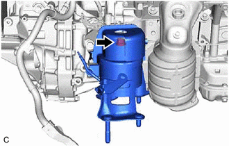
| (a) Remove the bolt and rear engine mounting insulator from the rear engine mounting bracket. |
|
| (b) Remove the bolt and wire harness clamp bracket from the rear engine mounting insulator. |
|
| (c) Disengage the clamp and remove the vacuum hose from the rear engine mounting insulator. |
|
Toyota Avalon (XX50) 2019-2022 Service & Repair Manual > Hybrid / Battery Control: Hv Battery Thermistor
Components COMPONENTS ILLUSTRATION *1 UPPER HV BATTERY COVER SUB-ASSEMBLY *2 HV BATTERY JUNCTION BLOCK ASSEMBLY *3 ELECTRIC VEHICLE BATTERY PLUG ASSEMBLY *4 WIRING HARNESS PROTECTOR N*m (kgf*cm, ft.*lbf): Specified torque - - ILLUSTRATION *1 NO. 2 HYBRID BATTERY SHIELD SUB-ASSEMBLY *2 NO. 1 HYBRID B ...