COMPONENTS
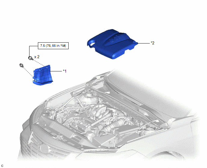
ILLUSTRATION
|
*1 | FRONT FENDER APRON SEAL RH |
*2 | V-BANK COVER SUB-ASSEMBLY |
 |
N*m (kgf*cm, ft.*lbf): Specified torque |
- | - |
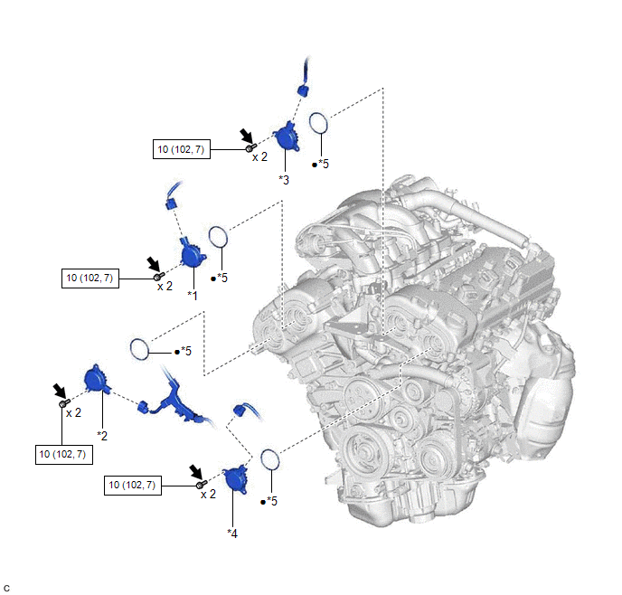
ILLUSTRATION
|
*1 | CAMSHAFT TIMING OIL CONTROL SOLENOID ASSEMBLY (for Intake Side of Bank 1) |
*2 | CAMSHAFT TIMING OIL CONTROL SOLENOID ASSEMBLY (for Exhaust Side of Bank 1) |
|
*3 | CAMSHAFT TIMING OIL CONTROL SOLENOID ASSEMBLY (for Intake Side of Bank 2) |
*4 | CAMSHAFT TIMING OIL CONTROL SOLENOID ASSEMBLY (for Exhaust Side of Bank 2) |
|
*5 | O-RING |
- | - |
|
|
N*m (kgf*cm, ft.*lbf): Specified torque |
● | Non-reusable part |
 |
Adhesive 1324 | ★ |
Precoated part |
INSPECTION
PROCEDURE
1. INSPECT CAMSHAFT TIMING OIL CONTROL SOLENOID ASSEMBLY
HINT:
Use the same procedure for the intake side and exhaust side.
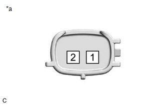
(a) Check the resistance.
| (1) Measure the resistance according to the value(s) in the table below. Standard Resistance:
If the result is not as specified, replace the camshaft timing oil control solenoid assembly. |
|
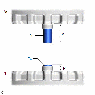
(b) Stroke Amount Inspection
| (1) Using vernier calipers, measure length (A) and (B) with the shaft of the camshaft timing oil control solenoid assembly set in the respective positions shown in the illustration. NOTICE: Do not apply battery voltage to the terminals of the camshaft timing oil control solenoid assembly. HINT: If the shaft does not extend under its own weight, extend the shaft with your fingers. |
|
(2) Calculate the stroke amount based on the difference of length (A) and (B).
Standard:
6.5 mm (0.256 in.) or more
HINT:
Stroke amount = length (A) - length (B)
If the value is not as specified, replace the camshaft timing oil control solenoid assembly.
INSTALLATION
PROCEDURE
1. INSTALL CAMSHAFT TIMING OIL CONTROL SOLENOID ASSEMBLY (for Intake Side of Bank 2)
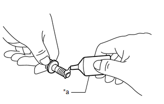
| (a) Apply engine oil to a new O-ring and install it to the camshaft timing oil control solenoid assembly as shown in the illustration. NOTICE: Do not damage the O-ring. |
|
| (b) Apply adhesive to 2 or 3 threads of 2 new bolts. Adhesive: Toyota Genuine Adhesive 1324, Three Bond 1324 or equivalent |
|
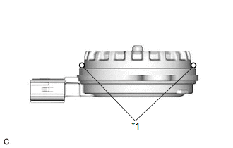
(c) Install the camshaft timing oil control solenoid assembly to the timing chain cover assembly with the 2 bolts.
Torque:
10 N·m {102 kgf·cm, 7 ft·lbf}
NOTICE:
(d) Connect the camshaft timing oil control solenoid assembly connector.
2. INSTALL ENGINE ASSEMBLY WITH TRANSAXLE
Click here

3. INSTALL CAMSHAFT TIMING OIL CONTROL SOLENOID ASSEMBLY (for Exhaust Side of Bank 1)
| (a) Apply engine oil to a new O-ring and install it to the camshaft timing oil control solenoid assembly as shown in the illustration. NOTICE: Do not damage the O-ring. |
|
| (b) Apply adhesive to 2 or 3 threads of 2 new bolts. Adhesive: Toyota Genuine Adhesive 1324, Three Bond 1324 or equivalent |
|
(c) Install the camshaft timing oil control solenoid assembly to the timing chain cover assembly with the 2 bolts.
Torque:
10 N·m {102 kgf·cm, 7 ft·lbf}
NOTICE:
(d) Connect the camshaft timing oil control solenoid assembly connector.
4. INSTALL FRONT FENDER APRON SEAL RH
Click here
5. INSTALL CAMSHAFT TIMING OIL CONTROL SOLENOID ASSEMBLY (for Intake Side of Bank 1)
| (a) Apply engine oil to a new O-ring and install it to the camshaft timing oil control solenoid assembly as shown in the illustration. NOTICE: Do not damage the O-ring. |
|
| (b) Apply adhesive to 2 or 3 threads of 2 new bolts. Adhesive: Toyota Genuine Adhesive 1324, Three Bond 1324 or equivalent |
|
(c) Install the camshaft timing oil control solenoid assembly to the timing chain cover assembly with the 2 bolts.
Torque:
10 N·m {102 kgf·cm, 7 ft·lbf}
NOTICE:
(d) Engage the clamp to connect the engine wire.
(e) Connect the camshaft timing oil control solenoid assembly connector.
6. INSTALL CAMSHAFT TIMING OIL CONTROL SOLENOID ASSEMBLY (for Exhaust Side of Bank 2)
| (a) Apply engine oil to a new O-ring and install it to the camshaft timing oil control solenoid assembly as shown in the illustration. NOTICE: Do not damage the O-ring. |
|
| (b) Apply adhesive to 2 or 3 threads of 2 new bolts. Adhesive: Toyota Genuine Adhesive 1324, Three Bond 1324 or equivalent |
|
(c) Install the camshaft timing oil control solenoid assembly to the timing chain cover assembly with the 2 bolts.
Torque:
10 N·m {102 kgf·cm, 7 ft·lbf}
NOTICE:
(d) Connect the camshaft timing oil control solenoid assembly connector.
7. INSPECT FOR ENGINE OIL LEAK
Click here
8. INSTALL V-BANK COVER SUB-ASSEMBLY
Click here
ON-VEHICLE INSPECTION
PROCEDURE
1. INSPECT CAMSHAFT TIMING OIL CONTROL SOLENOID ASSEMBLY
(a) Connect the Techstream to the DLC3.
(b) Start the engine.
(c) Turn the Techstream on.
(d) Inspect the camshaft timing oil control solenoid assembly (for intake side).
(1) Enter the following menus: Powertrain / Engine / Active Test / Control the Intake VVT OCV Duty Ratio Bank 1 or Control the Intake VVT OCV Duty Ratio Bank 2 / Data List / Intake VVT Change Angle Bank 1 or Intake VVT Change Angle Bank 2.
Powertrain > Engine > Active Test|
Active Test Display |
|---|
|
Control the Intake VVT OCV Duty Ratio Bank 1 |
|
Data List Display |
|---|
|
Intake VVT Change Angle Bank 1 |
|
Active Test Display |
|---|
|
Control the Intake VVT OCV Duty Ratio Bank 2 |
|
Data List Display |
|---|
|
Intake VVT Change Angle Bank 2 |
(2) Read the Data List while performing the Active Test with the engine idling.
OK:
|
Techstream Operation | Data List (Intake VVT Change Angle Bank 1 or Intake VVT Change Angle Bank 2) |
|---|---|
|
-100% to 100% | Varies by 70 DegFR or more |
If the result is not as specified, check the camshaft timing oil control solenoid assembly, wire harness and ECM.
(e) Inspect the camshaft timing oil control solenoid assembly (for exhaust side).
(1) Enter the following menus: Powertrain / Engine / Active Test / Control the Exhaust VVT OCV Duty Ratio Bank 1 or Control the Exhaust VVT OCV Duty Ratio Bank 2.
Powertrain > Engine > Active Test|
Tester Display |
|---|
| Control the Exhaust VVT OCV Duty Ratio Bank 1 |
|
Tester Display |
|---|
| Control the Exhaust VVT OCV Duty Ratio Bank 2 |
(2) Check the engine speed while operating the camshaft timing oil control solenoid assembly (for exhaust camshaft) using the Techstream.
OK:
|
Techstream Operation | Engine Condition |
|---|---|
|
0% | Normal engine speed |
|
100% | Engine idles roughly or stalls |
HINT:
Refer to "Data List / Active Test" [Exhaust VVT OCV Control Duty Ratio Bank 1, Exhaust VVT Change Angle Bank 1, Exhaust VVT OCV Control Duty Ratio Bank 2 and Exhaust VVT Change Angle Bank 2].
Click here

If the result is not as specified, check the camshaft timing oil control solenoid assembly, wire harness and ECM.
REMOVAL
CAUTION / NOTICE / HINT
The necessary procedures (adjustment, calibration, initialization, or registration) that must be performed after parts are removed and installed, or replaced during camshaft timing oil control solenoid assembly removal/installation are shown below.
Necessary Procedure After Parts Removed/Installed/Replaced|
Replaced Part or Performed Procedure |
Necessary Procedure | Effect/Inoperative Function when Necessary Procedure not Performed |
Link |
|---|---|---|---|
|
Battery terminal is disconnected/reconnected |
Perform steering sensor zero point calibration |
Lane departure alert system (w/ Steering Control) |
|
|
Pre-collision system | |||
|
Intelligent Clearance Sonar System*1 | |||
|
Lighting System (for Gasoline Model with Cornering Light) | |||
|
Memorize steering angle neutral point |
Parking Assist Monitor System |
| |
|
Panoramic View Monitor System |
| ||
|
Replacement of ECM | Vehicle Identification Number (VIN) registration |
MIL comes on |
|
|
ECU communication ID registration (Immobiliser system) |
Engine start function |
| |
|
Gas leak from exhaust system is repaired |
Inspection after repair |
|
|
|
Replacement of ECM (If transaxle compensation code read from ECM) |
|
|
|
|
Replacement of ECM (If transaxle compensation code not read from ECM) |
| ||
| Replacement of ECM |
Code registration (Smart Key System (for Start Function)) |
|
|
|
Suspension, tires, etc. |
|
|
|
|
Rear television camera assembly optical axis adjustment (Back camera position setting) |
Parking Assist Monitor System |
| |
| Panoramic View Monitor System |
| |
|
Perform headlight ECU sub-assembly LH initialization |
Lighting system (for Gasoline Model with Cornering Light) |
| |
|
Front wheel alignment adjustment |
Perform system variant learning and acceleration sensor zero point calibration. |
|
|
Click here 
PROCEDURE
1. REMOVE V-BANK COVER SUB-ASSEMBLY
Click here
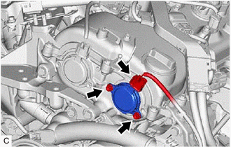
2. REMOVE CAMSHAFT TIMING OIL CONTROL SOLENOID ASSEMBLY (for Exhaust Side of Bank 2)
| (a) Disconnect the camshaft timing oil control solenoid assembly connector. |
|
(b) Remove the 2 bolts and camshaft timing oil control solenoid assembly from the timing chain cover assembly.
NOTICE:
If the camshaft timing oil control solenoid assembly has been struck or dropped, replace it.
(c) Remove the O-ring from the camshaft timing oil control solenoid assembly.
NOTICE:
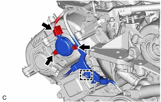
3. REMOVE CAMSHAFT TIMING OIL CONTROL SOLENOID ASSEMBLY (for Intake Side of Bank 1)
| (a) Disconnect the camshaft timing oil control solenoid assembly connector. |
|
(b) Disengage the clamp to disconnect the engine wire.
(c) Remove the 2 bolts and camshaft timing oil control solenoid assembly from the timing chain cover assembly.
NOTICE:
If the camshaft timing oil control solenoid assembly has been struck or dropped, replace it.
(d) Remove the O-ring from the camshaft timing oil control solenoid assembly.
NOTICE:
4. REMOVE FRONT FENDER APRON SEAL RH
Click here
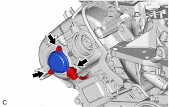
5. REMOVE CAMSHAFT TIMING OIL CONTROL SOLENOID ASSEMBLY (for Exhaust Side of Bank 1)
| (a) Disconnect the camshaft timing oil control solenoid assembly connector. |
|
(b) Remove the 2 bolts and camshaft timing oil control solenoid assembly from the timing chain cover assembly.
NOTICE:
If the camshaft timing oil control solenoid assembly has been struck or dropped, replace it.
(c) Remove the O-ring from the camshaft timing oil control solenoid assembly.
NOTICE:
6. REMOVE ENGINE ASSEMBLY WITH TRANSAXLE
Click here
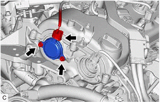
7. REMOVE CAMSHAFT TIMING OIL CONTROL SOLENOID ASSEMBLY (for Intake Side of Bank 2)
| (a) Disconnect the camshaft timing oil control solenoid assembly connector. |
|
(b) Remove the 2 bolts and camshaft timing oil control solenoid assembly from the timing chain cover assembly.
NOTICE:
If the camshaft timing oil control solenoid assembly has been struck or dropped, replace it.
(c) Remove the O-ring from the camshaft timing oil control solenoid assembly.
NOTICE:
Toyota Avalon (XX50) 2019-2022 Service & Repair Manual > 2gr-fks Intake / Exhaust: Intake System
On-vehicle Inspection ON-VEHICLE INSPECTION CAUTION / NOTICE / HINT The necessary procedures (adjustment, calibration, initialization or registration) that must be performed after parts are removed and installed, or replaced when repairing air leaks in the intake system are shown below. Necessary Pr ...