DTC SUMMARY
|
DTC No. | Detection Item |
DTC Detection Condition | Trouble Area |
MIL | Memory |
Note |
|---|---|---|---|---|---|---|
| P045500 |
Evaporative Emission System Leak Detected (Large Leak) |
Leak detection pump creates negative pressure (vacuum) in EVAP system and EVAP system pressure is measured. Reference pressure is measured at start and end of leak check. If stabilized pressure is higher than [second reference pressure x 0.2], ECM determines that EVAP system has a large leak. |
| Comes on |
DTC stored | SAE Code: P0455 |
|
P045600 | Evaporative Emission System Leak Detected (Very Small Leak) |
Leak detection pump creates negative pressure (vacuum) in EVAP system and EVAP system pressure is measured. Reference pressure measured at start and end of leak check. If stabilized pressure is higher than second reference pressure, ECM determines that EVAP system has a small leak. |
| Comes on |
DTC stored | SAE Code: P0456 |
|
DTC No. | Monitoring Item |
Detection Timing | Detection Logic |
SAE |
|---|---|---|---|---|
| P045500 |
EVAP gross leak |
EVAP monitoring (engine switch off) |
2 trip | P0455 |
|
P045600 | EVAP small leak |
P0456 |
DESCRIPTION
The description can be found in EVAP (Evaporative Emission) System.
Click here

MONITOR DESCRIPTION
5 hours* after the engine switch is turned off, the leak detection pump creates negative pressure (vacuum) in the EVAP (Evaporative Emission) system. The ECM monitors for leaks and actuator malfunctions based on the EVAP pressure.
HINT:
*: If the engine coolant temperature is not less than 35°C (95°F) 5 hours after the engine switch is turned off, the monitor check starts 2 hours later. If it is still not less than 35°C (95°F) 7 hours after the engine switch is turned off, the monitor check starts 2.5 hours later.
|
Sequence | Operation |
Description | Duration |
|---|---|---|---|
|
- | ECM activation |
Activated by soak timer 5, 7 or 9.5 hours after engine switch turned off. |
- |
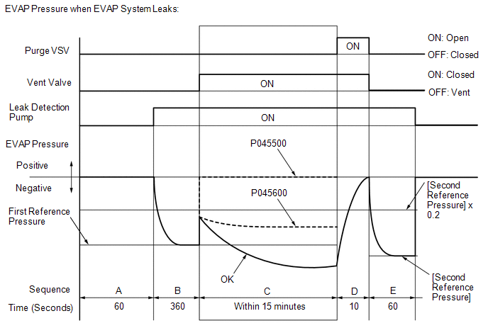
| A |
Atmospheric pressure measurement | Vent valve is turned off (vent) and EVAP system pressure is measured by ECM in order to register atmospheric pressure. If pressure in EVAP system is not between 70 to 110 kPa(abs) [10.15 to 15.95 psi(abs)], ECM cancels EVAP system monitor. |
60 seconds |
|
B | First reference pressure measurement |
In order to determine reference pressure, leak detection pump creates negative pressure (vacuum) through reference orifice and then ECM checks if leak detection pump and vent valve operate normally. |
360 seconds |
|
C | EVAP system pressure measurement |
Vent valve is turned on (closed) to shut EVAP system. Negative pressure (vacuum) is created in EVAP system, and EVAP system pressure is then measured. Write down measured value as it will be used in leak check. If EVAP pressure does not stabilize within 15 minutes, ECM cancels EVAP system monitor. |
15 minutes* |
|
D | Purge VSV monitor |
Purge VSV is opened and then EVAP system pressure is measured by ECM. Large increase indicates normal. |
10 seconds |
|
E | Second reference pressure measurement |
After second reference pressure measurement, leak check is performed by comparing first and second reference pressure measurements. If stabilized system pressure is higher than second reference pressure, ECM determines that EVAP system is leaking. |
60 seconds |
|
- | Final check |
Atmospheric pressure is measured and then monitoring result is recorded by ECM. |
- |
*: If only a small amount of fuel is in the fuel tank, it takes longer for the EVAP pressure to stabilize.
|
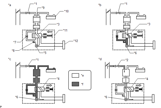
*1 | Purge VSV: Off (Closed) |
*2 | Purge VSV: On (Open) |
|
*3 | Vent Valve: Off (Vent) |
*4 | Vent Valve: On (Closed) |
|
*5 | Leak Detection Pump: Off |
*6 | Leak Detection Pump: On |
|
*7 | Reference Orifice (0.02 inch) |
*8 | Canister Pressure Sensor |
|
*9 | Canister |
*10 | Fuel Tank |
|
*11 | Canister Pump Module |
*12 | Canister Filter |
|
*a | Operation A: Atmospheric Pressure Measurement |
*b | Operation B, E: Reference Pressure Measurement |
|
*c | Operation C: EVAP System Pressure Measurement |
*d | Operation D: Purge VSV Monitor |
|
*e | Atmospheric Pressure |
*f | Negative Pressure |
In operation C, the leak detection pump creates negative pressure (vacuum) in the EVAP system and the EVAP system pressure is measured. If the stabilized system pressure is higher than [second reference pressure x 0.2] (near atmospheric pressure), the ECM determines that the EVAP system has a large leak, illuminates the MIL and stores this DTC (2 trip detection logic).
In operation C, the leak detection pump creates negative pressure (vacuum) in the EVAP system and the EVAP system pressure is measured. If the stabilized system pressure is higher than second reference pressure, the ECM determines that the EVAP system has a small leak, illuminates the MIL and stores this DTC (2 trip detection logic).
MONITOR STRATEGY
|
Required Sensors/Components (Main) | Purge VSV Canister pump module |
| Required Sensors/Components (Related) |
- |
| Frequency of Operation |
Once per driving cycle |
| Duration |
Within 20 minutes (varies with amount of fuel in tank) |
|
MIL Operation | 2 driving cycles |
|
Sequence of Operation | None |
TYPICAL ENABLING CONDITIONS
|
Atmospheric pressure | 70 kPa(abs) [10.15 psi(abs)] or higher, and less than 110 kPa(abs) [15.95 psi(abs)] |
|
Battery voltage | 10.5 V or higher |
|
Vehicle speed | Less than 4 km/h (2.5 mph) |
|
Engine switch | Off |
|
Time after key-off | 5, 7 or 9.5 hours |
|
Canister pressure sensor malfunction (P0452, P0453) |
Not detected |
| Purge VSV |
Not operated by scan tool |
|
Vent valve | Not operated by scan tool |
|
Leak detection pump | Not operated by scan tool |
|
Both of following conditions met before-key off |
1 and 2 |
| 1. Duration that vehicle is driven |
5 minutes or more |
| 2. EVAP purge operation |
Performed |
| Engine coolant temperature |
4.4°C (40°F) or higher, and less than 35°C (95°F) |
|
Intake air temperature | 4.4°C (40°F) or higher, and less than 35°C (95°F) |
TYPICAL MALFUNCTION THRESHOLDS
P0455: EVAP Gross Leak|
EVAP pressure when vacuum introduction is complete |
Higher than [reference pressure x 0.2] |
|
EVAP pressure when vacuum introduction is complete |
Between reference pressure and [reference pressure x 0.2] |
MONITOR RESULT
Refer to EVAP system.
Click here
CONFIRMATION DRIVING PATTERN
NOTICE:
HINT:
Click here
Click here
|
Techstream Display |
Description |
|---|---|
|
NORMAL |
|
|
ABNORMAL |
|
|
INCOMPLETE |
|
HINT:
The normal judgment procedure is used to complete DTC judgment and also used when clearing permanent DTCs.
PROCEDURE
|
1. | GO TO EVAP SYSTEM |
(a) Refer to EVAP System.
Click here
| NEXT |  | END |
DESCRIPTION
The fuel sender gauge is located inside the fuel tank and measures the amount of fuel. The fuel sender gauge converts the fuel level in the fuel tank into a voltage value and outputs it to the combination meter assembly. The ECM determines when it is necessary to refuel the vehicle based on changes in the output value of the fuel sender gauge.
|
DTC No. | Detection Item |
DTC Detection Condition | Trouble Area |
MIL | Memory |
Note |
|---|---|---|---|---|---|---|
| P046012 |
Fuel Level Sensor "A" Circuit Short to Battery |
Fuel sender gauge output voltage is higher than 4.73 V for 30 seconds or more (2 trip detection logic). |
| Comes on |
DTC stored | SAE Code: P0463 |
|
P046014 | Fuel Level Sensor "A" Circuit Short to Ground or Open |
Fuel sender gauge output voltage is less than 0.25 V for 30 seconds or more (2 trip detection logic). |
| Comes on |
DTC stored | SAE Code: P0462 |
MONITOR DESCRIPTION
The combination meter assembly sends fuel level sensor signals to the ECM via CAN communication. When the engine switch is on (IG), if the output voltage of the fuel level sensor is less than 0.25 V or higher than 4.73 V for 30 seconds or more, the ECM will illuminate the MIL and store this DTC.
MONITOR STRATEGY
|
Related DTCs | P0462: Fuel level sensor range check (low voltage) P0463: Fuel level sensor range check (high voltage) |
|
Required Sensors/Components (Main) | Fuel level sensor |
|
Required Sensors/Components (Related) |
- |
| Frequency of Operation |
Continuous |
| Duration |
30 seconds |
| MIL Operation |
2 driving cycles |
| Sequence of Operation |
None |
TYPICAL ENABLING CONDITIONS
|
All of the following conditions are met |
- |
| Battery voltage |
8 V or higher |
| Engine switch |
On (IG) |
| Lost communication with instrument panel cluster control module (U0155) |
Not detected |
TYPICAL MALFUNCTION THRESHOLDS
P0462|
Fuel level sensor voltage | Less than 0.25 V |
|
Fuel level sensor voltage | Higher than 4.73 V |
CONFIRMATION DRIVING PATTERN
HINT:
Click here 
Click here
HINT:
|
Techstream Display |
Description |
|---|---|
|
NORMAL |
|
|
ABNORMAL |
|
|
INCOMPLETE |
|
HINT:
The normal judgment procedure is used to complete DTC judgment and also used when clearing permanent DTCs.
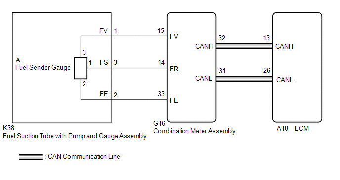
WIRING DIAGRAM
CAUTION / NOTICE / HINT
HINT:
Read freeze frame data using the Techstream. The ECM records vehicle and driving condition information as freeze frame data the moment a DTC is stored. When troubleshooting, freeze frame data can help determine if the vehicle was moving or stationary, if the engine was warmed up or not, if the air fuel ratio was lean or rich, and other data from the time the malfunction occurred.
PROCEDURE
| 1. |
CHECK HARNESS AND CONNECTOR (FUEL SUCTION TUBE WITH PUMP AND GAUGE ASSEMBLY - COMBINATION METER ASSEMBLY) |
(a) Disconnect the fuel suction tube with pump and gauge assembly connector.
(b) Disconnect the combination meter assembly connector.
(c) Measure the resistance according to the value(s) in the table below.
Standard Resistance:
|
Tester Connection | Condition |
Specified Condition |
|---|---|---|
|
K38-1 (FV) - G16-15 (FV) |
Always | Below 1 Ω |
|
K38-3 (FS) - G16-14 (FR) |
Always | Below 1 Ω |
|
K38-2 (FE) - G16-33 (FE) |
Always | Below 1 Ω |
|
K38-1 (FV) or G16-15 (FV) - Body ground and other terminals |
Always | 10 kΩ or higher |
|
K38-3 (FS) or G16-14 (FR) - Body ground and other terminals |
Always | 10 kΩ or higher |
| NG |  | REPAIR OR REPLACE HARNESS OR CONNECTOR |
|
| 2. |
INSPECT FUEL SENDER GAGE ASSEMBLY |
(a) Remove the fuel sender gauge assembly.
Click here
(b) Inspect the fuel sender gauge assembly.
Click here
| NG | | REPLACE FUEL SENDER GAGE ASSEMBLY |
|
| 3. |
INSPECT FUEL SUCTION TUBE WITH PUMP AND GAUGE ASSEMBLY |
|
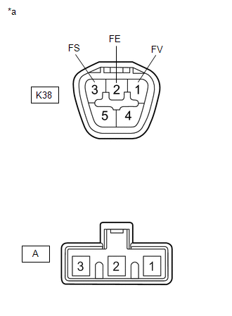
*a | Component without harness connected (Fuel Suction Tube with Pump and Gauge Assembly) |
(a) Measure the resistance according to the value(s) in the table below.
Standard Resistance:
|
Tester Connection | Condition |
Specified Condition |
|---|---|---|
|
K38-1 (FV) - A-3 | Always |
Below 1 Ω |
|
K38-2 (FE) - A-2 | Always |
Below 1 Ω |
|
K38-3 (FS) - A-1 | Always |
Below 1 Ω |
|
K38-1 (FV) - K38-3 (FS) or A-3 - A-1 |
Always | 10 kΩ or higher |
|
K38-1 (FV) - K38-2 (FE) or A-3 - A-2 |
Always | 10 kΩ or higher |
|
K38-2 (FE) - K38-3 (FS) or A-2 - A-1 |
Always | 10 kΩ or higher |
| OK | | REPLACE COMBINATION METER ASSEMBLY |
| NG | | REPLACE FUEL SUCTION TUBE WITH PUMP AND GAUGE ASSEMBLY |
DESCRIPTION
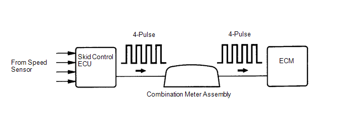
Vehicles, which are equipped with ABS (Anti-lock Brake System), detect the vehicle speed using the skid control ECU (brake actuator assembly) and speed sensor. The speed sensor monitors the wheel rotation speed and sends a signal to the skid control ECU. The skid control ECU converts the wheel speed signal into a 4-pulse signal and transmits it to the ECM via the combination meter assembly. The ECM determines the vehicle speed based on the frequency of the pulse signal.
HINT:
The signal is changed to a pulse signal at the transistor in the combination meter assembly. Each ECU controls the respective system based on the pulse signal.
|
DTC No. | Detection Item |
DTC Detection Condition | Trouble Area |
MIL | Memory |
Note |
|---|---|---|---|---|---|---|
| P050031 |
Vehicle Speed Sensor "A" No Signal |
While vehicle being driven, no vehicle speed sensor signal transmitted to ECM (2 trip detection logic). |
| Comes on |
DTC stored | SAE Code: P0500 |
MONITOR DESCRIPTION
If there is no speed signal from the combination meter assembly even though the ECM determines that the vehicle is being driven, the ECM interprets this as a malfunction in the speed signal circuit. The ECM then illuminates the MIL and stores this DTC.
MONITOR STRATEGY
|
Related DTCs | P0500: Vehicle speed sensor verify pulse input |
|
Required Sensors/Components (Main) | Vehicle speed sensor Combination meter Skid control ECU |
|
Required Sensors/Components (Related) |
Park/neutral position switch Engine coolant temperature sensor Crankshaft position sensor Speed Sensor Throttle position sensor Mass air flow meter sub-assembly |
|
Frequency of Operation | Continuous |
|
Duration | 5 seconds |
|
MIL Operation | 2 driving cycles |
|
Sequence of Operation | None |
TYPICAL ENABLING CONDITIONS
|
All of the following conditions are met | - |
|
Battery voltage | 8 V or higher |
|
Engine switch | On (IG) |
|
Starter | Off |
|
Time after engine switch off to on (IG) |
3 seconds or more |
| Engine |
Running |
| Vehicle speed sensor monitor condition |
Met |
| Lost communication with TCM (U0101) |
Not detected |
TYPICAL MALFUNCTION THRESHOLDS
|
Vehicle speed sensor signal | No signal |
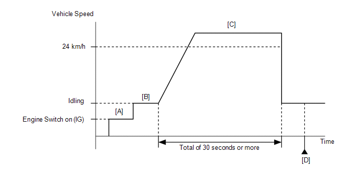
CONFIRMATION DRIVING PATTERN
HINT:
Click here 
Click here
CAUTION:
When performing the confirmation driving pattern, obey all speed limits and traffic laws.
HINT:
|
Techstream Display |
Description |
|---|---|
|
NORMAL |
|
|
ABNORMAL |
|
|
INCOMPLETE |
|
HINT:
The normal judgment procedure is used to complete DTC judgment and also used when clearing permanent DTCs.
WIRING DIAGRAM
CAUTION / NOTICE / HINT
HINT:
Read freeze frame data using the Techstream. The ECM records vehicle and driving condition information as freeze frame data the moment a DTC is stored. When troubleshooting, freeze frame data can help determine if the vehicle was moving or stationary, if the engine was warmed up or not, if the air fuel ratio was lean or rich, and other data from the time the malfunction occurred.
PROCEDURE
| 1. |
READ VALUE USING TECHSTREAM (VEHICLE SPEED) |
(a) Connect the Techstream to the DLC3.
(b) Turn the engine switch on (IG).
(c) Turn the Techstream on.
(d) Enter the following menus: Powertrain / Engine / Data List / Vehicle Speed.
Powertrain > Engine > Data List|
Tester Display |
|---|
| Vehicle Speed |
(e) Drive the vehicle.
(f) Read the value displayed on the Techstream.
|
Result | Proceed to |
|---|---|
|
Values displayed on Techstream and speedometer display not equal |
A |
| Values displayed on Techstream and speedometer display equal |
B |
| B |
 | CHECK FOR INTERMITTENT PROBLEMS |
|
| 2. |
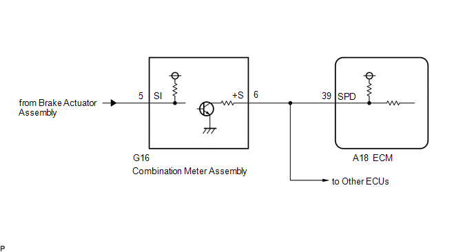
CHECK HARNESS AND CONNECTOR (COMBINATION METER ASSEMBLY - ECM) |
(a) Disconnect the combination meter assembly connector.
(b) Disconnect the ECM connector.
(c) Measure the resistance according to the value(s) in the table below.
Standard Resistance:
|
Tester Connection | Condition |
Specified Condition |
|---|---|---|
| G16-6 (+S) - A18-39 (SPD) |
Always | Below 1 Ω |
| NG | | REPAIR OR REPLACE HARNESS OR CONNECTOR |
|
| 3. |
CHECK COMBINATION METER SYSTEM |
(a) Check the circuits that send vehicle speed signals to this system in the combination meter system.
Click here
|
| 4. |
CLEAR DTC |
(a) Connect the Techstream to the DLC3.
(b) Turn the engine switch on (IG).
(c) Turn the Techstream on.
(d) Clear the DTC.
Powertrain > Engine > Clear DTCs(e) Turn the engine switch off and wait for at least 30 seconds.
|
| 5. |
CONFIRM WHETHER MALFUNCTION HAS BEEN SUCCESSFULLY REPAIRED |
(a) Drive the vehicle in accordance with the driving pattern described in Confirmation Driving Pattern.
(b) Enter the following menus: Powertrain / Engine / Trouble Codes.
(c) Read the DTCs.
Powertrain > Engine > Trouble CodesHINT:
If no DTCs (no pending DTCs) are output to the Techstream, the repair has been successfully completed.
| NEXT | | END |
Toyota Avalon (XX50) 2019-2022 Service & Repair Manual > Park Assist / Monitoring: Panoramic View Monitor System(for Hv Model)
"CHK" message(s) are displayed on the SIGNAL CHECK screen. DESCRIPTION On the SIGNAL CHECK screen, it is possible to check if the signals sent to the parking assist ECU are normal. Click here HINT: On the SIGNAL CHECK screen, "OK" (blue) is displayed for items with a normal inspection result or inpu ...


