MONITOR DESCRIPTION
The battery supplies electricity to the ECM even when the engine switch is off. This power allows the ECM to store data such as DTC history, freeze frame data and fuel trim values. If the battery voltage falls below a minimum level, the memory is cleared and the ECM determines that there is a malfunction in the power supply circuit. The next time the engine is started, the ECM will illuminate the MIL and store this DTC.
|
DTC No. | Detection Item |
DTC Detection Condition | Trouble Area |
MIL | Memory |
Note |
|---|---|---|---|---|---|---|
| P056014 |
System Voltage Circuit Short to Ground or Open |
An open or short in the ECM backup power source circuit (1 trip detection logic). |
| Comes on |
DTC stored | SAE Code: P0562 |
MONITOR STRATEGY
|
Related DTCs | P0562: ECM system voltage range check (low voltage) |
|
Required Sensors/Components (Main) | ECM |
|
Required Sensors/Components (Related) |
- |
| Frequency of Operation |
Continuous |
| Duration |
3 seconds |
| MIL Operation |
Immediate |
| Sequence of Operation |
None |
TYPICAL ENABLING CONDITIONS
|
Monitor runs whenever the following DTCs are not stored |
None |
| All of the following conditions are met |
- |
| Battery voltage | 8 V or higher |
|
Engine switch | On (IG) |
| Starter |
Off |
TYPICAL MALFUNCTION THRESHOLDS
|
Both of the following conditions are met |
- |
| Battery voltage (BATT) |
Less than 3.5 V |
| Electronic throttle actuator power supply voltage (+BM) |
Less than 3.5 V |
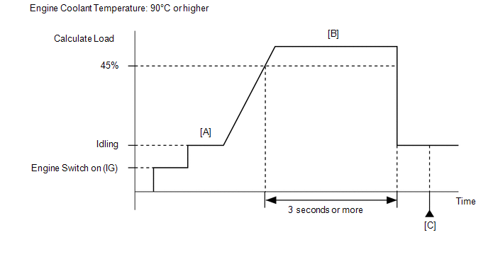
CONFIRMATION DRIVING PATTERN
HINT:
Click here 
Click here
HINT:
|
Techstream Display |
Description |
|---|---|
|
NORMAL |
|
|
ABNORMAL |
|
|
INCOMPLETE |
|
HINT:
The normal judgment procedure is used to complete DTC judgment and also used when clearing permanent DTCs.
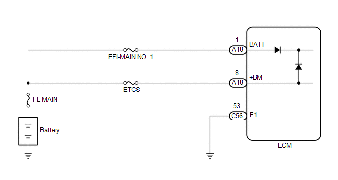
WIRING DIAGRAM
CAUTION / NOTICE / HINT
NOTICE:
Click here
HINT:
Read freeze frame data using the Techstream. The ECM records vehicle and driving condition information as freeze frame data the moment a DTC is stored. When troubleshooting, freeze frame data can help determine if the vehicle was moving or stationary, if the engine was warmed up or not, if the air fuel ratio was lean or rich, and other data from the time the malfunction occurred.
PROCEDURE
| 1. |
INSPECT BATTERY |
(a) Inspect the battery.
Click here
OK:
Battery voltage is between 11 to 14 V.
| NG |  | CHARGE OR REPLACE BATTERY |
|
| 2. |
CHECK BATTERY TERMINAL |
(a) Check that the battery terminals are not loose or corroded.
OK:
Battery terminals are not loose or corroded
| NG | | REPAIR OR REPLACE BATTERY TERMINAL |
|
| 3. |
CHECK HARNESS AND CONNECTOR (POWER SOURCE OF ECM) |
|
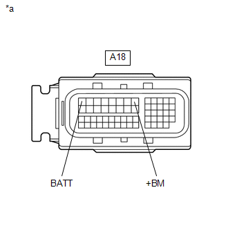
*a | Front view of wire harness connector (to ECM) |
(a) Disconnect the ECM connector.
(b) Measure the voltage according to the value(s) in the table below.
Standard Voltage:
|
Tester Connection | Condition |
Specified Condition |
|---|---|---|
|
A18-1 (BATT) - Body ground |
Always | 11 to 14 V |
|
A18-8 (+BM) - Body ground |
Always | 11 to 14 V |
| NG | | REPAIR OR REPLACE HARNESS OR CONNECTOR (BATTERY - ECM) |
|
| 4. |
CLEAR DTC |
(a) Connect the Techstream to the DLC3.
(b) Turn the engine switch on (IG).
(c) Turn the Techstream on.
(d) Clear the DTC.
Powertrain > Engine > Clear DTCs(e) Turn the engine switch off and wait for at least 30 seconds.
|
| 5. |
CHECK WHETHER DTC OUTPUT RECURS (DTC P056014) |
(a) Drive the vehicle in accordance with the driving pattern described in Confirmation Driving Pattern.
(b) Enter the following menus: Powertrain / Engine / Trouble Codes.
(c) Read the DTCs.
Powertrain > Engine > Trouble Codes|
Result | Proceed to |
|---|---|
|
DTCs are not output | A |
|
DTC P056014 is output |
B |
| A |
| CHECK FOR INTERMITTENT PROBLEMS |
| B |
| REPLACE ECM |
DESCRIPTION
An electric heater is equipped to the temperature sensing portion of the thermostat. During normal driving, current does not flow to the heater and the thermostat functions as an ordinary thermostat. When the temperature of the engine increases by a large amount such as during high-load driving, control is performed to warm the heater of the temperature sensing portion, forcing the valve to open and causing a large amount of coolant to flow to the radiator.
|
DTC No. | Detection Item |
DTC Detection Condition | Trouble Area |
MIL | Memory |
Note |
|---|---|---|---|---|---|---|
| P059712 |
Thermostat Heater Control Circuit Short to Battery |
Short in thermostat heater circuit and power supply circuit (1 trip detection logic). |
| Comes on |
DTC stored | SAE Code: P0599 |
MONITOR DESCRIPTION
The ECM monitors the output voltage while the thermostat heater is operating.
The thermostat heater turns on and off according to ON/OFF switching of a transistor inside the ECM.
If a continuous mismatch occurs between the ECM transistor state and the output voltage, the ECM determines there is a malfunction in the thermostat heater circuit and stores a DTC.
MONITOR STRATEGY
|
Related DTCs | P0599: Thermostat heater range check (high voltage) |
|
Required Sensors/Components (Main) | Thermostat heater |
|
Required Sensors/Components (Related) | - |
|
Frequency of Operation | Continuous |
|
Duration | 3 seconds |
| MIL Operation |
Immediate |
| Sequence of Operation |
None |
TYPICAL ENABLING CONDITIONS
|
Monitor runs whenever the following DTCs are not stored |
None |
| All of the following conditions are met |
- |
| Either of the following conditions is met |
1 or 2 |
| 1. Both of the following conditions are met |
(a) and (b) |
| (a) Last command to thermostat heater |
Off |
| (b) Current command to thermostat heater |
Off |
| 2. Both of the following conditions are met |
(c) and (d) |
|
(c) Last command to thermostat heater |
On |
| (d) Current command to thermostat heater |
On |
| Battery voltage |
8 V or higher |
|
Starter | Off |
|
Command to thermostat heater |
On |
TYPICAL MALFUNCTION THRESHOLDS
|
Thermostat heater output terminal voltage level |
High |
CONFIRMATION DRIVING PATTERN
HINT:
Click here 
Click here
CAUTION:
When performing the confirmation driving pattern, obey all speed limits and traffic laws.
HINT:
|
Techstream Display |
Description |
|---|---|
|
NORMAL |
|
|
ABNORMAL |
|
|
INCOMPLETE |
|
HINT:
The normal judgment procedure is used to complete DTC judgment and also used when clearing permanent DTCs.
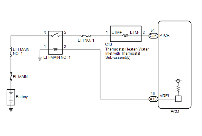
WIRING DIAGRAM
CAUTION / NOTICE / HINT
NOTICE:
Inspect the fuses for circuits related to this system before performing the following procedure.
HINT:
Read freeze frame data using the Techstream. The ECM records vehicle and driving condition information as freeze frame data the moment a DTC is stored. When troubleshooting, freeze frame data can help determine if the vehicle was moving or stationary, if the engine was warmed up or not, if the air fuel ratio was lean or rich, and other data from the time the malfunction occurred.
PROCEDURE
| 1. |
CHECK HARNESS AND CONNECTOR (WATER INLET WITH THERMOSTAT SUB-ASSEMBLY - ECM) |
(a) Disconnect the water inlet with thermostat sub-assembly connector.
(b) Disconnect the ECM connector.
(c) Measure the resistance according to the value(s) in the table below.
Standard Resistance:
|
Tester Connection | Condition |
Specified Condition |
|---|---|---|
|
C43-2 (ETM-) or C56-64 (PTCR) - Other terminals |
Always | 10 kΩ or higher |
| OK |  | REPLACE ECM |
| NG | | REPAIR OR REPLACE HARNESS OR CONNECTOR |
DESCRIPTION
Refer to DTC P059712.
Click here

|
DTC No. | Detection Item |
DTC Detection Condition | Trouble Area |
MIL | Memory |
Note |
|---|---|---|---|---|---|---|
| P059714 |
Thermostat Heater Control Circuit Short to Ground or Open |
Open or short in thermostat heater circuit and power supply circuit (1 trip detection logic). |
| Comes on |
DTC stored | SAE Code: P0598 |
MONITOR DESCRIPTION
The ECM monitors the output voltage while the thermostat heater is operating.
The thermostat heater turns on and off according to ON/OFF switching of a transistor inside the ECM.
If a continuous mismatch occurs between the ECM transistor state and the output voltage, the ECM determines there is a malfunction in the thermostat heater circuit and stores a DTC.
MONITOR STRATEGY
|
Related DTCs | P0598: Thermostat heater range check (low voltage) |
|
Required Sensors/Components (Main) | Thermostat heater |
|
Required Sensors/Components (Related) | - |
|
Frequency of Operation | Continuous |
|
Duration | 3 seconds |
| MIL Operation |
Immediate |
| Sequence of Operation |
None |
TYPICAL ENABLING CONDITIONS
|
Monitor runs whenever the following DTCs are not stored |
None |
| All of the following conditions are met |
- |
| Either of the following conditions is met |
1 or 2 |
| 1. Both of the following conditions are met |
(a) and (b) |
| (a) Last command to thermostat heater |
Off |
| (b) Current command to thermostat heater |
Off |
| 2. Both of the following conditions are met |
(c) and (d) |
|
(c) Last command to thermostat heater |
On |
| (d) Current command to thermostat heater |
On |
| Battery voltage |
8 V or higher |
|
Starter | Off |
|
Command to thermostat heater |
Off |
TYPICAL MALFUNCTION THRESHOLDS
|
Thermostat heater output terminal voltage level |
Low |
CONFIRMATION DRIVING PATTERN
HINT:
Click here
Click here

CAUTION:
When performing the confirmation driving pattern, obey all speed limits and traffic laws.
HINT:
|
Techstream Display |
Description |
|---|---|
|
NORMAL |
|
|
ABNORMAL |
|
|
INCOMPLETE |
|
HINT:
The normal judgment procedure is used to complete DTC judgment and also used when clearing permanent DTCs.
WIRING DIAGRAM
Refer to DTC P059712.
Click here
CAUTION / NOTICE / HINT
NOTICE:
Inspect the fuses for circuits related to this system before performing the following procedure.
HINT:
Read freeze frame data using the Techstream. The ECM records vehicle and driving condition information as freeze frame data the moment a DTC is stored. When troubleshooting, freeze frame data can help determine if the vehicle was moving or stationary, if the engine was warmed up or not, if the air fuel ratio was lean or rich, and other data from the time the malfunction occurred.
PROCEDURE
| 1. |
CHECK TERMINAL VOLTAGE (POWER SOURCE OF WATER INLET WITH THERMOSTAT SUB-ASSEMBLY) |
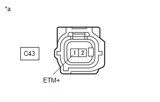
|
*a | Front view of wire harness connector (to Water Inlet with Thermostat Sub-assembly) |
(a) Disconnect the water inlet with thermostat sub-assembly connector.
(b) Turn the engine switch on (IG).
(c) Measure the voltage according to the value(s) in the table below.
Standard Voltage:
|
Tester Connection | Condition |
Specified Condition |
|---|---|---|
|
C43-1 (ETM+) - Body ground |
Engine switch on (IG) |
11 to 14 V |
| NG |  | REPAIR OR REPLACE HARNESS OR CONNECTOR (EFI-MAIN NO. 1 RELAY - WATER INLET WITH THERMOSTAT SUB-ASSEMBLY) |
|
| 2. |
INSPECT WATER INLET WITH THERMOSTAT SUB-ASSEMBLY |
(a) Inspect the water inlet with thermostat sub-assembly.
Click here
| NG | |
REPLACE WATER INLET WITH THERMOSTAT SUB-ASSEMBLY |
|
| 3. |
CHECK HARNESS AND CONNECTOR (WATER INLET WITH THERMOSTAT SUB-ASSEMBLY - ECM) |
(a) Disconnect the water inlet with thermostat sub-assembly connector.
(b) Disconnect the ECM connector.
(c) Measure the resistance according to the value(s) in the table below.
Standard Resistance:
|
Tester Connection | Condition |
Specified Condition |
|---|---|---|
|
C43-2 (ETM-) - C56-64 (PTCR) |
Always | Below 1 Ω |
|
C43-2 (ETM-) or C56-64 (PTCR) - Body ground and other terminals |
Always | 10 kΩ or higher |
| NG | | REPAIR OR REPLACE HARNESS OR CONNECTOR |
|
| 4. |
CLEAR DTC |
(a) Connect the Techstream to the DLC3.
(b) Turn the engine switch on (IG).
(c) Turn the Techstream on.
(d) Clear the DTC.
Powertrain > Engine > Clear DTCs(e) Turn the engine switch off and wait for at least 30 seconds.
|
| 5. |
CHECK WHETHER DTC OUTPUT RECURS (DTC P059714) |
(a) Drive the vehicle in accordance with the driving pattern described in Confirmation Driving Pattern.
(b) Enter the following menus: Powertrain / Engine / Trouble Codes.
(c) Read the DTCs.
Powertrain > Engine > Trouble Codes|
Result | Proceed to |
|---|---|
|
DTCs are not output | A |
|
DTC P059714 is output |
B |
| A |
| CHECK FOR INTERMITTENT PROBLEMS |
| B |
| REPLACE ECM |
Toyota Avalon (XX50) 2019-2022 Owners Manual > Using the driving
support systems: PCS
(Pre-Collision System)
The pre-collision system uses a radar sensor and camera sensor to detect vehicles and pedestrians in front of your vehicle. When the system determines that the possibility of a frontal collision with a vehicle or pedestrian is high, a warning operates to urge the driver to take evasive action and t ...


