DESCRIPTION This DTC is
stored when the engine does not start even though the STA signal is
input or when the engine takes a long time to start, and when the engine
speed is low or the engine stalls just after the engine starts. Using
the Techstream, the conditions present when the DTC was stored can be
confirmed by referring to the freeze frame data. Freeze frame data
records engine conditions when a malfunction occurs. This information
can be useful when troubleshooting. It is
necessary to check if the vehicle ran out of fuel before performing
troubleshooting, as this DTC is also stored when there is engine
starting trouble due to running out of fuel. |
DTC No. | Detection Item |
DTC Detection Condition | MIL |
Memory | Note | |
P160400 | Startability Malfunction |
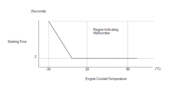
Either conditions is met (1 trip detection logic):
- The engine speed is below 500 rpm with the STA signal on for a certain amount of time (refer to the illustration below).
- After the engine starts (engine speed is 500 rpm or more), the engine
speed drops to 200 rpm or less within approximately 2 seconds.
| Does not come on |
DTC stored | SAE Code: P1604 |
 |
Trouble Area | | Ignition system |
- Spark plug
- Ignition coil assembly
| | Fuel system |
- Fuel injector assembly (for direct injection)
- Fuel injector assembly (for port injection)
- Fuel pump assembly (for high pressure side)
- Fuel pump (for low pressure side)
- Fuel pump control circuit
- Fuel suction plate sub-assembly
- Fuel main valve assembly
- Fuel line
- Purge VSV system
- Fuel quality (existence of foreign matter, degradation)
| | Intake and exhaust systems |
| | Other control systems |
- ECM
- Wire harness or connector
- Knock control sensor
- Engine coolant temperature sensor
| | Engine |
- Water inlet with thermostat sub-assembly
- Engine assembly
| | High load from another system |
- Air conditioning system
- Power steering system
- Electrical load signal system
- A/T system
| CAUTION / NOTICE / HINT
HINT:
- DTC P160400
- In contrast to normal malfunction diagnosis for components, circuits and
systems, DTC P160400 is used to determine the malfunctioning area from
the problem symptoms and freeze frame data when the user mentions
problems such as starting difficulty.
As this DTC can be stored as a result of certain user
actions, even if the DTC is output, if the customer makes no mention of
problems, clear the DTC without performing any troubleshooting and
return the vehicle to the customer.
- As DTCs may be stored when an Active Test or learning is performed, make
sure to clear the DTCs before returning the vehicle to the customer.
- If any other DTCs are output, perform troubleshooting for those DTCs first.
- DATA LIST / FREEZE FRAME DATA
- When this Data List item "Immobiliser Communication" is OFF or
"Immobiliser Fuel Cut Status" is ON, the engine cannot be started.
- Read freeze frame data using the Techstream. Freeze frame data records
engine conditions when a malfunction occurs. This information can be
useful when troubleshooting.
- When confirming the freeze frame data, be sure to check all multi freeze frame data.
Click here 
- When confirming the freeze frame data, if there are multiple items
related to the cause of the malfunction, perform troubleshooting for all
related items.
- Try to start the vehicle under the conditions recorded in the freeze
frame data which were present when the malfunction occurred. Confirm the
data at this time and compare it with the freeze frame data.
- If the malfunction does not recur, carefully check the vehicle
conditions from when the malfunction occurred using freeze frame data.
- PRECAUTIONS
- When performing inspections, jiggle the relevant wire harnesses and
connectors in an attempt to reproduce malfunctions that do not always
occur.
- If the same inspection or replacement procedure appears 2 times when
performing an inspection procedure, it is not necessary to repeat the
procedure the second time.
PROCEDURE |
1. | CHECK FOR ANY OTHER DTCS OUTPUT |
(a) Connect the Techstream to the DLC3. (b) Turn the engine switch on (IG).
(c) Turn the Techstream on. (d) Enter the following menus: Powertrain / Engine / Trouble Codes.
(e) Read the DTCs. Powertrain > Engine > Trouble Codes
|
Result | Proceed to | |
DTC P160400 is output |
A | | DTC P160400 and other DTCs are output |
B |
HINT:
- If any DTCs other than P160400 is output, troubleshoot those DTCs first.
- Using freeze frame data, confirm the conditions the moment the DTC was
stored and after the DTC was stored. This information can be useful when
troubleshooting.
| B |
 | GO TO DTC CHART |
|
A |
 | |
| 2. |
READ FREEZE FRAME DATA (IMMOBILISER COMMUNICATION AND IMMOBILISER FUEL CUT STATUS) |
(a) Connect the Techstream to the DLC3. (b) Turn the engine switch on (IG).
(c) Turn the Techstream on. (d)
Using the Techstream, confirm the vehicle conditions recorded in the
freeze frame data which were present when the DTC was stored. Click here
OK: |
Data List Item | Techstream Display | |
Immobiliser Communication |
ON | | Immobiliser Fuel Cut Status |
OFF |
HINT:
- If the engine is started immediately after reconnecting the battery
terminal, the engine may stall immediately after it starts due to the
intercommunication process between each ECU. For this reason, when
starting the engine after reconnecting the battery terminal, first turn
the engine switch on (IG) and then wait several seconds for the
communication process to complete before starting the engine.
- When this operation causes DTC P160400 to be stored, this is due to
normal operation of the immobiliser system and does not indicate a
malfunction, so clear the DTC and return the vehicle to the customer.
| NG |
| CHECK IMMOBILISER SYSTEM |
|
OK | |
| |
| 3. |
READ FREEZE FRAME DATA (ISC F/B LEARN TORQUE) |
(a) Connect the Techstream to the DLC3. (b) Turn the engine switch on (IG).
(c) Turn the Techstream on. (d)
Using the Techstream, confirm the vehicle conditions recorded in the
freeze frame data which were present when the DTC was stored. Click here
|
Freeze Frame Data Item | Result |
Suspected Area | Action |
Proceed to | |
ISC F/B Learn Torque |
Less than 30 Nm | - |
Go to the next step | A | |
30 Nm or higher | Throttle body with motor assembly |
Go to ENGINE DIFFICULT TO START (from step 15) |
B |
| B |
| GO TO ENGINE DIFFICULT TO START |
|
A | |
| |
| 4. |
READ FREEZE FRAME DATA (ENGINE SPEED) |
(a) Connect the Techstream to the DLC3. (b) Turn the engine switch on (IG).
(c) Turn the Techstream on. (d)
Using the Techstream, confirm the vehicle conditions recorded in the
freeze frame data which were present when the DTC was stored. Click here
|
Freeze Frame Data Item | Result |
Suspected Area | Action |
Proceed to | |
Engine Speed | All 5 sets of freeze frame data are 0 rpm (engine did not crank or engine speed was not detected properly) |
- Starter signal circuit
- Crankshaft position sensor system
- Battery fully depleted
| Go to ENGINE DIFFICULT TO START (from step 5) |
A | | 100 to 500 rpm (engine cranked but initial combustion did not occur or was delayed) |
- Fuel pump
- Leaking fuel injector assembly
- Spark plug
- Ignition coil assembly
| Go to the next step |
B | | 500 rpm or higher (engine speed dropped immediately after initial combustion)
(Low Revolution for Engine Start is ON) |
- Spark plug
- Ignition coil assembly
|
| A |
| GO TO ENGINE DIFFICULT TO START |
|
B | |
| |
| 5. |
INTERVIEW THE CUSTOMER | (a) Interview the customer for details about the conditions when the malfunction occurred.
HINT: If
the engine is difficult to start only when the vehicle has been left as
is for a long time, a leaking fuel injector assembly is suspected.
|
Result | Suspected Area |
Action | Proceed to | |
Engine is difficult to start only when the vehicle has been left as is for a long time (1 hour or more) |
Leaking fuel injector assembly |
Go to ENGINE DIFFICULT TO START (from step 4) |
A | | Other than above |
- Fuel pump
- Spark plug
- Ignition coil assembly
| Go to the next step |
B |
| A |
| GO TO ENGINE DIFFICULT TO START |
|
B | |
| |
| 6. |
INTERVIEW THE CUSTOMER | (a) Interview the customer for details about the conditions when the malfunction occurred.
HINT: If
the vehicle is mostly driven for short distances, deposits may have
accumulated on the spark plugs, causing starting difficulty.
|
Result | Suspected Area |
Action | Proceed to | |
Mostly driven short distances |
- Spark plug
- Ignition coil assembly
| Go to ENGINE DIFFICULT TO START (from step 13) |
NEXT | | Not mostly driven short distances |
- Fuel pump
- Spark plug
- Ignition coil assembly
| Go to ENGINE DIFFICULT TO START (from step 9) |
| NEXT |
| GO TO ENGINE DIFFICULT TO START | | 

