DESCRIPTION
This DTC is stored if the combustion state of any cylinder is unstable.
Using the Techstream, the conditions present when the DTC was stored can be confirmed by referring to the freeze frame data. Freeze frame data records engine conditions when a malfunction occurs. This information can be useful when troubleshooting.
It is necessary to check if the vehicle ran out of fuel before performing troubleshooting, as this DTC is also stored when idling is unstable due to running out of fuel.
|
DTC No. | Detection Item |
DTC Detection Condition | MIL |
Memory | Note |
|---|---|---|---|---|---|
|
P160500 | Rough Idling |
When idling with the accelerator pedal released and the vehicle stopped, this item detects when the combustion is worsening at predetermined levels from the changes in engine speed between the cylinders. Detection for 2 to 10 seconds according to the combustion state (1 trip detection logic). |
Does not come on | DTC stored |
SAE Code: P1605 |
|
Trouble Area | |
|---|---|
| Ignition system |
|
| Fuel system |
|
| Intake and exhaust systems |
|
| Other control systems |
|
| Engine |
|
| High load from another system |
|
CAUTION / NOTICE / HINT
HINT:
Such problem symptoms can occur even in the following conditions:
Click here 
PROCEDURE
|
1. | CHECK FOR ANY OTHER DTCS OUTPUT |
(a) Connect the Techstream to the DLC3.
(b) Turn the engine switch on (IG).
(c) Turn the Techstream on.
(d) Enter the following menus: Powertrain / Engine / Trouble Codes.
(e) Read the DTCs.
Powertrain > Engine > Trouble Codes|
Result | Proceed to |
|---|---|
|
Only DTC P160500 is output |
A |
| DTCs other than P160500 are output |
B |
HINT:
| B |  | GO TO DTC CHART |
|
| 2. |
READ FREEZE FRAME DATA |
(a) Connect the Techstream to the DLC3.
(b) Turn the engine switch on (IG).
(c) Turn the Techstream on.
(d) Using the Techstream, confirm the vehicle conditions recorded in the freeze frame data which were present when the DTC was stored.
Click here
|
Freeze Frame Data Item for DTC P160500 |
Suspected Area |
Action | Proceed to | |
|---|---|---|---|---|
| Compression Leakage Count | |||
|
"One of Rough Idle Cylinder #1 to #6 is ON" and "Plural Cylinders Rough Idle is OFF" |
4 or less |
| Go to ROUGH IDLING (from step 7) |
A |
| Plural Cylinders Rough Idle is ON |
4 or less |
| Go to ROUGH IDLING (from step 15) |
B |
| "One of Rough Idle Cylinder #1 to #6 are ON" or "Plural Cylinders Rough Idle is ON" |
5 or more | Pressure loss from valve damage, deposits jamming the valve etc. |
Check compression and clean deposits in combustion chamber and intake system. |
C |
| B |
| GO TO STEP 4 |
| C |
| GO TO STEP 5 |
|
| 3. |
DETERMINE CAUSE OF MALFUNCTION FOR INDIVIDUAL CYLINDER |
(a) Perform troubleshooting from Rough Idling step 7 (PERFORM ACTIVE TEST USING TECHSTREAM (CHECK THE CYLINDER COMPRESSION) and onward.
Click here
| NEXT | |
GO TO ROUGH IDLING |
| 4. |
DETERMINE CAUSE OF MALFUNCTION FOR MULTIPLE OR ALL CYLINDERS |
(a) Perform troubleshooting from Rough Idling step 15 (READ VALUE USING TECHSTREAM (MASS AIR FLOW SENSOR)) and onward.
Click here
| NEXT | | GO TO ROUGH IDLING |
| 5. |
PERFORM ACTIVE TEST USING TECHSTREAM (CHECK THE CYLINDER COMPRESSION) |
(a) Warm up the engine.
(b) Turn the engine switch off.
(c) Connect the Techstream to the DLC3.
(d) Turn the engine switch on (IG).
(e) Turn the Techstream on.
(f) Enter the following menus: Powertrain / Engine / Active Test / Check the Cylinder Compression / Data List / Compression / Engine Speed Cylinder #1 to #6 and Average Engine Speed of All Cylinder.
Powertrain > Engine > Active Test|
Active Test Display |
|---|
|
Check the Cylinder Compression |
|
Data List Display |
|---|
|
Engine Speed Cylinder #1 |
|
Engine Speed Cylinder #2 |
|
Engine Speed Cylinder #3 |
|
Engine Speed Cylinder #4 |
|
Engine Speed Cylinder #5 |
|
Engine Speed Cylinder #6 |
|
Average Engine Speed of All Cylinder |
HINT:
To display the entire Data List, press the pull down menu button next to Primary. Then select Compression.
(g) Push the snapshot button to turn the snapshot function on.
HINT:
Using the snapshot function, data can be recorded during the Active Test.
(h) While the engine is not running, press the Active test button to change Check the Cylinder Compression to "Start".
HINT:
After performing the above procedure, Check the Cylinder Compression will start. Fuel injection for all cylinders is prohibited and each cylinder engine speed measurement enters standby mode.
(i) Crank the engine for about 10 seconds.
(j) Monitor the engine speed (Engine Speed Cylinder #1 to #6 and Average Engine Speed of All Cylinder) displayed on the Techstream.
HINT:
NOTICE:
(k) Stop cranking the engine, and then change "Check the Cylinder Compression" to "Stop" after the engine stops.
NOTICE:
(l) Push the snapshot button to turn the snapshot function off.
(m) Select "Stored Data" on the Techstream screen, select the recorded data and display the data as a graph.
HINT:
If the data is not displayed as a graph, the change of the values cannot be observed.
(n) Read the value.
HINT:
|
Result | Proceed to |
|---|---|
|
There is no variation in "Engine Speed Cylinder #1 to #6" (All cylinders display approximately the same value for "Engine Speed Cylinder #1 to #6") |
A |
| There is variation in "Engine Speed Cylinder #1 to #6" (Only one cylinder displays a value for "Engine Speed Cylinder #1 to #6" that differs considerably) |
B |
| A |
| CLEAN OFF ANY DEPOSITS |
|
| 6. |
CHECK CYLINDER COMPRESSION PRESSURE |
(a) Measure the cylinder compression pressure. If the compression pressure of a cylinder is low, inspect the engine assembly and repair or replace parts as necessary.
Click here
| NEXT | | END |
MONITOR DESCRIPTION
The ECM continuously monitors its main and sub CPUs. This self-check ensures that the ECM is functioning properly. If outputs from the CPUs are different and deviate from the standard, the ECM will illuminate the MIL and store the DTC immediately.
|
DTC No. | Detection Item |
DTC Detection Condition | Trouble Area |
MIL | Memory |
Note |
|---|---|---|---|---|---|---|
| P160700 |
Cruise Control Input Processor |
ECM CPUs malfunction (1 trip detection logic). |
ECM | Comes on |
DTC stored | SAE Code: P1607 |
MONITOR STRATEGY
|
Related DTC | P1607: Internal control module performance |
|
Required Sensors/Components (Main) | ECM |
|
Required Sensors/Components (Related) | Cruise control |
|
Frequency of Operation | Continuous |
|
Duration | 0.3 seconds |
| MIL Operation |
Immediate |
| Sequence of Operation |
None |
TYPICAL ENABLING CONDITIONS
|
Monitor runs whenever the following DTCs are not stored |
None |
| Both of the following conditions are met |
- |
| Cruise control |
Forbidden |
| DMA communication error |
Not detected |
TYPICAL MALFUNCTION THRESHOLDS
|
Cruise control | Operating |
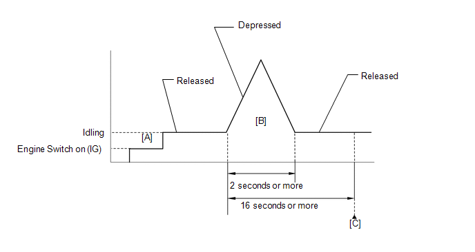
CONFIRMATION DRIVING PATTERN
HINT:
Click here 
Click here
HINT:
|
Techstream Display |
Description |
|---|---|
|
NORMAL |
|
|
ABNORMAL |
|
|
INCOMPLETE |
|
HINT:
The normal judgment procedure is used to complete DTC judgment and also used when clearing permanent DTCs.
CAUTION / NOTICE / HINT
NOTICE:
After turning engine switch off, waiting time may be required before disconnecting the cable from the negative (-) battery terminal. Therefore, make sure to read the disconnecting the cable from the negative (-) battery terminal notices before proceeding with work.
Click here
HINT:
Read freeze frame data using the Techstream. The ECM records vehicle and driving condition information as freeze frame data the moment a DTC is stored. When troubleshooting, freeze frame data can help determine if the vehicle was moving or stationary, if the engine was warmed up or not, if the air fuel ratio was lean or rich, and other data from the time the malfunction occurred.
PROCEDURE
| 1. |
CLEAR DTC |
(a) Connect the Techstream to the DLC3.
(b) Turn the engine switch on (IG).
(c) Turn the Techstream on.
(d) Clear the DTC.
Powertrain > Engine > Clear DTCs(e) Turn the engine switch off.
|
| 2. |
READ OUTPUT DTC (DTC P160700) |
(a) Disconnect the cable from the negative (-) battery terminal and wait for 1 minute.
(b) Connect the cable to the negative (-) battery terminal.
(c) Connect the Techstream to the DLC3.
(d) Turn the engine switch on (IG) and turn the Techstream on.
(e) Wait 16 seconds or more.
(f) Enter the following menus: Powertrain / Engine / Trouble Codes.
(g) Read the DTCs.
Powertrain > Engine > Trouble Codes|
Result | Proceed to |
|---|---|
|
DTCs are not output | A |
|
DTC P160700 is output |
B |
| A |
 | CHECK FOR INTERMITTENT PROBLEMS |
| B |
| REPLACE ECM |
DESCRIPTION
The throttle actuator is operated by the ECM and opens and closes the throttle valve using gears.
The opening angle of the throttle valve is detected by the throttle position sensor, which is mounted on the throttle body with motor assembly. The throttle position sensor provides feedback to the ECM. This feedback allows the ECM to appropriately control the throttle actuator and monitor the throttle opening angle as the ECM responds to driver inputs.
HINT:
This Electronic Throttle Control System (ETCS) does not use a throttle cable.
|
DTC No. | Detection Item |
DTC Detection Condition | Trouble Area |
MIL | Memory |
Note |
|---|---|---|---|---|---|---|
| P210014 |
Throttle Actuator "A" Control Motor Circuit Short to Ground or Open |
Both of the following conditions are met for 2 seconds (1 trip detection logic):
|
| Comes on |
DTC stored | SAE Code: P2102 |
|
P210015 | Throttle Actuator "A" Control Motor Circuit Short to Battery or Open |
Either of the following conditions is met (1 trip detection logic):
|
| Comes on |
DTC stored | SAE Code: P2103 |
MONITOR DESCRIPTION
The ECM monitors the electrical current through the electronic actuator, and detects malfunctions and open circuits in the throttle actuator based on this value. If the current is outside the standard range, the ECM determines that there is a malfunction in the throttle actuator. In addition, if the throttle valve does not function properly (for example, stuck on), the ECM determines that there is a malfunction. The ECM then illuminates the MIL and stores a DTC.
MONITOR STRATEGY
|
Related DTCs | P2102: Electronic throttle actuator control motor range check (low current) P2103: Electronic throttle actuator control motor range check (high current) |
|
Required Sensors/Components (Main) | Throttle actuator (throttle body with motor assembly) |
|
Required Sensors/Components (Related) |
- |
| Frequency of Operation |
Continuous |
| Duration |
2 seconds: P2102 0.1 seconds: P2103 (case 1) 0.6 seconds: P2103 (case 2) |
|
MIL Operation | Immediate |
|
Sequence of Operation | None |
TYPICAL ENABLING CONDITIONS
All|
Monitor runs whenever the following DTCs are not stored |
None |
|
All of the following conditions are met |
- |
| Command to electronic throttle actuator |
On |
| Output duty cycle |
80% or higher |
| Electronic throttle actuator power supply voltage |
8 V or higher |
| Motor current change during last 0.016 seconds |
Less than 0.2 A |
|
Both of the following conditions are met |
- |
| Command to electronic throttle actuator power |
On |
| Either of the following conditions is met |
1 or 2 |
| 1. Electronic throttle actuator power supply voltage |
8 V or higher |
| 2. Electronic throttle actuator power |
On |
TYPICAL MALFUNCTION THRESHOLDS
P2102|
Throttle actuator current | Less than 0.5 A |
|
Motor driver IC high current limiter monitor input |
Fail |
|
Motor driver IC high current inhibit signal | On |
CONFIRMATION DRIVING PATTERN
HINT:
Click here 
Click here
HINT:
|
Techstream Display |
Description |
|---|---|
|
NORMAL |
|
|
ABNORMAL |
|
|
INCOMPLETE |
|
HINT:
The normal judgment procedure is used to complete DTC judgment and also used when clearing permanent DTCs.
FAIL-SAFE
When any of these DTCs or other DTCs relating to Electronic Throttle Control System (ETCS) malfunctions are stored, the ECM enters fail-safe mode. During fail-safe mode, the ECM cuts the current to the throttle actuator, and the throttle valve is returned to a 7° throttle valve opening angle by the return spring. The ECM then adjusts the engine output by controlling the fuel injection (intermittent fuel-cut) and ignition timing, in accordance with the accelerator pedal opening angle, to allow the vehicle to continue running at a minimal speed. If the accelerator pedal is depressed firmly and gently, the vehicle can be driven slowly.
Fail-safe mode continues until a pass condition is detected, and the engine switch is then turned off.
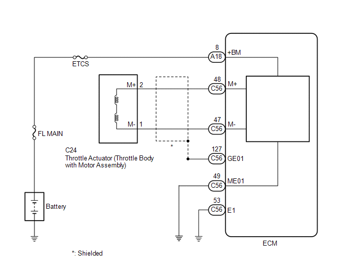
WIRING DIAGRAM
CAUTION / NOTICE / HINT
NOTICE:
Inspect the fuses for circuits related to this system before performing the following procedure.
HINT:
PROCEDURE
|
1. | INSPECT THROTTLE BODY WITH MOTOR ASSEMBLY (RESISTANCE OF THROTTLE ACTUATOR) |
(a) Inspect the throttle body with motor assembly.
Click here
HINT:
Perform "Inspection After Repair" after replacing the throttle body with motor assembly.
Click here
| NG |  | REPLACE THROTTLE BODY WITH MOTOR ASSEMBLY |
|
| 2. |
CHECK HARNESS AND CONNECTOR (THROTTLE BODY WITH MOTOR ASSEMBLY - ECM) |
(a) Disconnect the throttle body with motor assembly connector.
(b) Disconnect the ECM connector.
(c) Measure the resistance according to the value(s) in the table below.
Standard Resistance:
|
Tester Connection | Condition |
Specified Condition |
|---|---|---|
|
C24-2 (M+) - C56-48 (M+) |
Always | Below 1 Ω |
|
C24-1 (M-) - C56-47 (M-) |
Always | Below 1 Ω |
|
C24-2 (M+) or C56-48 (M+) - Body ground and other terminals |
Always | 10 kΩ or higher |
|
C24-1 (M-) or C56-47 (M-) - Body ground and other terminals |
Always | 10 kΩ or higher |
| NG | | REPAIR OR REPLACE HARNESS OR CONNECTOR |
|
| 3. |
INSPECT THROTTLE BODY WITH MOTOR ASSEMBLY (VISUALLY CHECK THROTTLE VALVE) |
(a) Check for foreign matter between the throttle valve and the housing.
OK:
No foreign matter between the throttle valve and housing.
HINT:
Perform "Inspection After Repair" after replacing the throttle body with motor assembly.
Click here
| NG | | REMOVE FOREIGN MATTER AND CLEAN THROTTLE BODY WITH MOTOR ASSEMBLY |
|
| 4. |
INSPECT THROTTLE BODY WITH MOTOR ASSEMBLY (THROTTLE VALVE) |
(a) Check if the throttle valve opens and closes smoothly.
OK:
Throttle valve opens and closes smoothly.
HINT:
Perform "Inspection After Repair" after replacing the throttle body with motor assembly.
Click here
| OK | | REPLACE ECM |
| NG | | REPLACE THROTTLE BODY WITH MOTOR ASSEMBLY |
Toyota Avalon (XX50) 2019-2022 Service & Repair Manual > Electronically Controlled Brake System(for Gasoline Model): Speed Sensor Rotor Faulty (C1237)
DESCRIPTION The skid control ECU (brake actuator assembly) measures the speed of each wheel by receiving signals from each speed sensor. These signals are used for recognizing that all four wheels are operating properly. Therefore, signals from all wheels must be equal. DTC No. Detection Item DTC De ...


