DTC SUMMARY
|
DTC No. | Detection Item |
DTC Detection Condition | Trouble Area |
MIL | Memory |
Note |
|---|---|---|---|---|---|---|
| P261029 |
ECM/PCM Engine Off Timer Performance Signal Invalid |
ECM internal malfunction |
ECM | Comes on |
DTC stored | SAE Code: P2610 |
|
P261093 | ECM/PCM Engine Off Timer Performance No Operation |
ECM internal malfunction |
ECM | Comes on |
DTC stored | SAE Code: P2610 |
|
DTC No. | Monitoring Item |
Detection Timing | Detection Logic |
|---|---|---|---|
|
P261029 | Soak timer (built into ECM) |
EVAP monitoring (engine switch off) |
2 trip |
| P261093 |
Soak timer (built into ECM) | Engine switch on (IG) |
2 trip |
DESCRIPTION
The soak timer operates after the engine switch is turned off. When a certain amount of time has elapsed after turning the engine switch off, the soak timer activates the ECM to perform malfunction checks which can only be performed after the engine is stopped. The soak timer is built into the ECM.
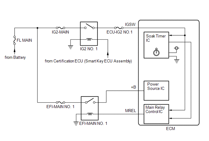
MONITOR DESCRIPTION
If the soak timer activates the ECM even though only a short amount of time has elapsed since the engine switch was turned off, or if the soak timer does not activate the ECM even though a considerable amount of time has elapsed since the engine switch was turned off, the ECM determines that the soak timer is malfunctioning, illuminates the MIL and stores a DTC the next time the engine switch is turned on (IG).
MONITOR STRATEGY
|
Related DTC | P2610: ECM internal engine off timer performance |
|
Required Sensors/Components (Main) | ECM |
|
Required Sensors/Components (Related) |
- |
| Frequency of Operation |
Once per driving cycle |
| Duration |
2 times: Case 1 -: Case 2 and 3 |
|
MIL Operation | 2 driving cycles |
|
Sequence of Operation | None |
TYPICAL ENABLING CONDITIONS
All|
Monitor runs whenever the following DTCs are not stored |
None |
|
All of the following conditions are met |
- |
| Battery voltage |
8 V or higher |
| Engine switch |
Off |
| Internal Engine OFF Timer clear record |
Off |
|
All of the following conditions are met |
- |
| Internal engine off timer (elapsed time from engine stop) |
10 minutes or more, and less than 30 minutes |
|
Battery voltage | 8 V or higher |
|
Engine switch | On (IG) |
|
Starter | Off |
|
All of the following conditions are met |
- |
| Internal engine off timer (elapsed time from engine stop) |
40 minutes or more |
| Battery voltage |
8 V or higher |
| Engine switch |
On (IG) |
| Starter |
Off |
TYPICAL MALFUNCTION THRESHOLDS
Case 1|
One of the following conditions is met | A, B or C |
|
A. Both of the following conditions are met |
- |
| Internal engine off timer |
9.375 seconds or more |
| CPU clock elapsed time |
1.96608 seconds or more, and less than 8.323072 seconds |
|
B. Both of the following conditions are met |
- |
| Internal engine off timer |
18.75 seconds or more |
| CPU clock elapsed time |
8.323072 to 10.42022 seconds |
|
C. Both of the following conditions are met |
- |
| Internal engine off timer |
Less than 9.375 seconds |
| CPU clock elapsed time |
More than 10.42022 seconds |
|
ECM started by internal engine off timer last trip |
Yes |
|
ECM started by internal engine off timer last trip |
No |
CONFIRMATION DRIVING PATTERN
HINT:
Click here 
Click here
HINT:
|
Techstream Display |
Description |
|---|---|
|
NORMAL |
|
|
ABNORMAL |
|
|
INCOMPLETE |
|
HINT:
The normal judgment procedure is used to complete DTC judgment and also used when clearing permanent DTCs.
CAUTION / NOTICE / HINT
HINT:
PROCEDURE
|
1. | REPLACE ECM |
(a) Replace the ECM.
Click here
|
| 2. |
CLEAR DTC |
(a) Connect the Techstream to the DLC3.
(b) Turn the engine switch on (IG).
(c) Turn the Techstream on.
(d) Clear the DTC.
Powertrain > Engine > Clear DTCs(e) Turn the engine switch off and wait for at least 30 seconds.
|
| 3. |
CHECK WHETHER DTC OUTPUT RECURS (DTC P261029 OR P261093) |
(a) Drive the vehicle in accordance with the driving pattern described in Confirmation Driving Pattern.
(b) Enter the following menus: Powertrain / Engine / Trouble Codes / Pending.
Powertrain > Engine > Trouble Codes(c) If no pending DTC is output, the repair has been successfully completed.
| NEXT |  | END |
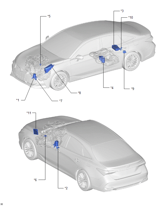
PARTS LOCATION
ILLUSTRATION
|
*1 | FRONT ENGINE MOUNTING INSULATOR |
*2 | REAR ENGINE MOUNTING INSULATOR |
|
*3 | CANISTER |
*4 | FUEL PUMP (for Low Pressure Side) |
|
*5 | MASS AIR FLOW METER SUB-ASSEMBLY |
*6 | PARK / NEUTRAL POSITION SWITCH ASSEMBLY |
|
*7 | VACUUM SWITCHING VALVE (for Active Control Engine Mount System) |
*8 | NO. 1 ENGINE ROOM RELAY BLOCK AND NO. 1 JUNCTION BLOCK ASSEMBLY |
|
*9 | CANISTER PUMP MODULE |
*10 | FUEL PUMP CONTROL ECU |
|
*11 | ECM |
- | - |
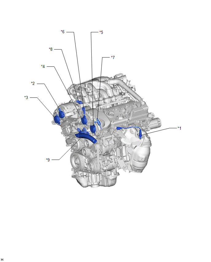
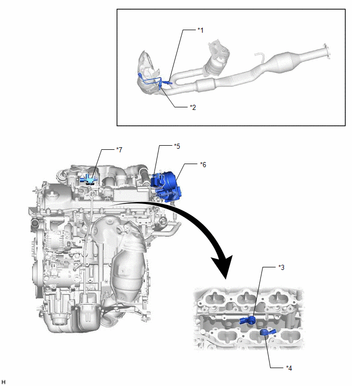
ILLUSTRATION
|
*1 | AIR FUEL RATIO SENSOR (Bank 2 Sensor 1) |
*2 | CAM TIMING OIL CONTROL SOLENOID ASSEMBLY (for Intake Camshaft of Bank 1) |
|
*3 | CAM TIMING OIL CONTROL SOLENOID ASSEMBLY (for Exhaust Camshaft of Bank 1) |
*4 | CAM TIMING OIL CONTROL SOLENOID ASSEMBLY (for Intake Camshaft of Bank 2) |
|
*5 | CAM TIMING OIL CONTROL SOLENOID ASSEMBLY (for Exhaust Camshaft of Bank 2) |
*6 | FUEL INJECTOR ASSEMBLY (for Port Injection) |
|
*7 | FUEL INJECTOR ASSEMBLY (for Direct Injection) |
*8 | FUEL PRESSURE SENSOR (for Low Pressure Side) |
|
*9 | WATER INLET WITH THERMOSTAT SUB-ASSEMBLY |
- | - |
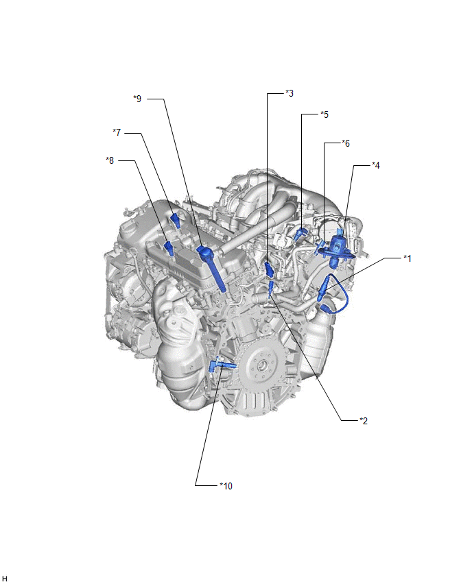
ILLUSTRATION
|
*1 | AIR FUEL RATIO SENSOR (Bank 1 Sensor 1) |
*2 | ENGINE COOLANT TEMPERATURE SENSOR |
|
*3 | FUEL PRESSURE SENSOR (for High Pressure Side) |
*4 | FUEL PUMP ASSEMBLY (for High Pressure Side) |
|
*5 | VVT SENSOR (for Intake Camshaft of Bank 1) |
*6 | VVT SENSOR (for Exhaust Camshaft of Bank 1) |
|
*7 | VVT SENSOR (for Intake Camshaft of Bank 2) |
*8 | VVT SENSOR (for Exhaust Camshaft of Bank 2) |
|
*9 | IGNITION COIL ASSEMBLY |
*10 | CRANKSHAFT POSITION SENSOR |
ILLUSTRATION
|
*1 | HEATED OXYGEN SENSOR (Bank 2 Sensor 2) |
*2 | HEATED OXYGEN SENSOR (Bank 1 Sensor 2) |
|
*3 | KNOCK CONTROL SENSOR (Bank 1) |
*4 | KNOCK CONTROL SENSOR (Bank 2) |
|
*5 | PURGE VSV |
*6 | THROTTLE BODY WITH MOTOR ASSEMBLY |
|
*7 | NO. 1 VACUUM SWITCHING VALVE (for Intake Air Control Valve Sub-assembly) |
- | - |
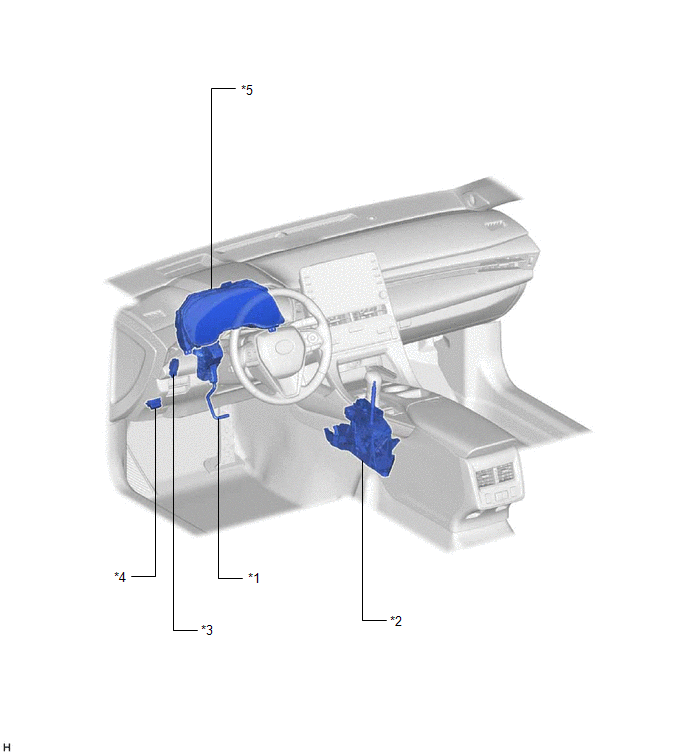
ILLUSTRATION
|
*1 | ACCELERATOR PEDAL SENSOR ASSEMBLY |
*2 | TRANSMISSION CONTROL SWITCH (SHIFT LOCK CONTROL UNIT ASSEMBLY) |
|
*3 | STOP LIGHT SWITCH ASSEMBLY |
*4 | DLC3 |
|
*5 | COMBINATION METER ASSEMBLY |
- | - |
PRECAUTION
INITIALIZATION
NOTICE:
Click here 
Click here
Click here
Click here
|
System Name |
See Procedure |
|---|---|
|
Lane Departure Alert System (w/ Steering Control) |
|
|
Intelligent Clearance Sonar System |
|
|
Parking Assist Monitor System |
|
|
Panoramic View Monitor System |
|
|
Pre-collision System |
|
|
Lighting System (for Gasoline Model with Cornering Light) |
WHEN USING TECHSTREAM
CAUTION:
Observe the following items for safety reasons:
Toyota Avalon (XX50) 2019-2022 Service & Repair Manual > Audio And Visual System(for Hv Model): Touch Panel Switch does not Function. Sending Malfunction (Navigation to APGS) (U0073,U0100,U0129,U0140,U0155,U0164,U0198,U0265,U0293). USB Audio System Recognition/Play Error
Touch Panel Switch does not Function CAUTION / NOTICE / HINT NOTICE: Depending on the parts that are replaced during vehicle inspection or maintenance, performing initialization, registration or calibration may be needed. Refer to Precaution for Audio and Visual System. Click here When replacing the ...


