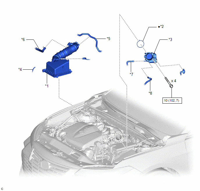
COMPONENTS
ILLUSTRATION
|
*1 | AIR CLEANER CAP WITH AIR CLEANER HOSE |
*2 | THROTTLE BODY GASKET |
|
*3 | THROTTLE BODY WITH MOTOR ASSEMBLY |
*4 | VACUUM HOSE |
|
*5 | NO. 1 FUEL VAPOR FEED HOSE |
*6 | NO. 2 VENTILATION HOSE |
|
*7 | NO. 2 WATER BY-PASS HOSE |
*8 | NO. 3 WATER BY-PASS HOSE |
 |
N*m (kgf*cm, ft.*lbf): Specified torque |
● | Non-reusable part |
INSPECTION
PROCEDURE
1. INSPECT THROTTLE BODY WITH MOTOR ASSEMBLY
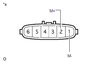
| (a) Measure the resistance according to the value(s) in the table below. Standard Resistance:
If the result is not as specified, replace the throttle body with motor assembly. |
|
INSTALLATION
PROCEDURE
1. INSTALL THROTTLE BODY GASKET
| (a) Install a new throttle body gasket to the intake air surge tank assembly with the protrusion of the throttle body gasket oriented as shown in the illustration. |
|
2. INSTALL THROTTLE BODY WITH MOTOR ASSEMBLY
HINT:
Perform "Inspection After Repair" after replacing the throttle body with motor assembly.
Click here 
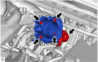
(a) Install the throttle body with motor assembly to the intake air surge tank assembly with the 4 bolts.
Torque:
10 N·m {102 kgf·cm, 7 ft·lbf}
NOTICE:
If the throttle body with motor assembly has been struck or dropped, replace it.
(b) Connect the throttle body with motor assembly connector.
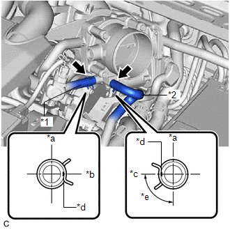
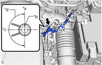
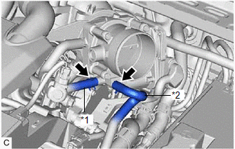
| (c) Connect the No. 2 water by-pass hose and No. 3 water by-pass hose to the throttle body with motor assembly and slide the 2 clips to secure them. NOTICE: Make sure to position each clip as shown in the illustration. |
|
3. INSTALL AIR CLEANER CAP WITH AIR CLEANER HOSE
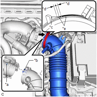
| (a) Install the air cleaner cap with air cleaner hose to the throttle body with motor assembly. NOTICE: Align the cutout of the air cleaner hose assembly with the protrusion of the throttle body with motor assembly. |
|
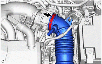
(b) Tighten the hose clamp in the position shown in the illustration.
NOTICE:
Make sure that the end of the hose clamp is positioned as shown in the illustration.
(c) Engage the 2 guides.
(d) Engage the 2 air cleaner cap clamps to install the air cleaner cap sub-assembly to the air cleaner case sub-assembly.
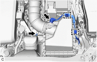
| (e) Connect the No. 2 ventilation hose to the air cleaner hose and slide the clip to secure it. NOTICE: Make sure to position the clip as shown in the illustration. |
|
(f) Engage the 2 clamps to connect the No. 1 fuel vapor feed hose to the air cleaner hose.
(g) Connect the vacuum hose to the air cleaner hose.
(h) Engage the 2 wire harness clamps.
(i) Connect the mass air flow meter sub-assembly connector.
4. ADD ENGINE COOLANT
Click here
5. INSPECT FOR COOLANT LEAK
Click here
6. PERFORM INITIALIZATION
NOTICE:
(a) Connect the Techstream to the DLC3.
(b) Turn the engine switch on (IG).
(c) Turn the Techstream on.
(d) Clear the DTCs.
Powertrain > Engine > Clear DTCs(e) Perform "Inspection After Repair".
Click here
(f) Start the engine and check that the MIL is not illuminated. After the engine is warmed up, check that the idle speed is within the specified range with the A/C switch off.
Standard Idle Speed:
600 to 700 rpm
NOTICE:
(g) Enter the following menus: Powertrain / Engine / Data List / Throttle Position Sensor No.1 Voltage %.
Powertrain > Engine > Data List|
Tester Display |
|---|
| Throttle Position Sensor No.1 Voltage % |
(h) Fully depress the accelerator pedal and check that the value is 60% or higher.
(i) Perform a road test and confirm that there are no abnormalities.
ON-VEHICLE INSPECTION
PROCEDURE
1. INSPECT THROTTLE BODY WITH MOTOR ASSEMBLY
(a) Check the idle speed.
(1) Start the engine and check that the MIL is not illuminated. After the engine is warmed up, check that the idle speed is within the specified range with the A/C switch off.
Standard Idle Speed:
600 to 700 rpm
NOTICE:
(2) Perform a road test and confirm that there are no abnormalities.
(b) Inspect the throttle position sensor.
(1) Connect the Techstream to the DLC3.
(2) Start the engine.
(3) Turn the Techstream on.
(4) Enter the following menus: Powertrain / Engine / Data List / Throttle Position Sensor No.1 Voltage %.
Powertrain > Engine > Data List|
Tester Display |
|---|
| Throttle Position Sensor No.1 Voltage % |
(5) Fully depress the accelerator pedal and check that the value is 60% or higher.
If the percentage is less than 60%, check the throttle body with motor assembly, wire harness and ECM.
REMOVAL
CAUTION / NOTICE / HINT
The necessary procedures (adjustment, calibration, initialization, or registration) that must be performed after parts are removed and installed, or replaced during throttle body with motor assembly removal/installation are shown below.
Necessary Procedures After Parts Removed/Installed/Replaced|
Replaced Part or Performed Procedure |
Necessary Procedure | Effect/Inoperative Function when Necessary Procedure not Performed |
Link |
|---|---|---|---|
| Inspection after repair |
|
|
PROCEDURE
1. DRAIN ENGINE COOLANT
Click here 
2. REMOVE AIR CLEANER CAP WITH AIR CLEANER HOSE
| (a) Disconnect the mass air flow meter sub-assembly connector. |
|
(b) Disengage the 2 wire harness clamps.
(c) Disconnect the vacuum hose from the air cleaner hose.
| (d) Disengage the 2 clamps to disconnect the No. 1 fuel vapor feed hose from the air cleaner hose. |
|
(e) Slide the clip and disconnect the No. 2 ventilation hose from the air cleaner hose.
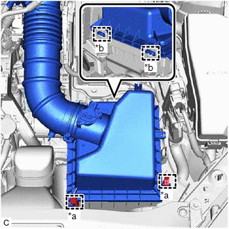
| (f) Disengage the 2 air cleaner cap clamps. |
|
(g) Disengage the 2 guides to separate the air cleaner cap sub-assembly from the air cleaner case sub-assembly.
| (h) Loosen the hose clamp and remove the air cleaner cap with air cleaner hose from the throttle body with motor assembly. |
|
3. REMOVE THROTTLE BODY WITH MOTOR ASSEMBLY
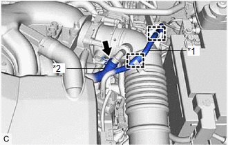
| (a) Slide the 2 clips and disconnect the No. 2 water by-pass hose and No. 3 water by-pass hose from the throttle body with motor assembly. |
|
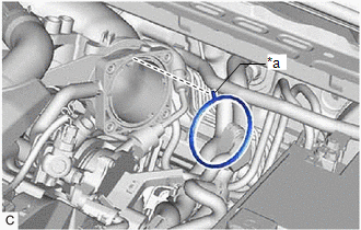
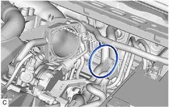
| (b) Disconnect the throttle body with motor assembly connector. |
|
(c) Remove the 4 bolts and throttle body with motor assembly from the intake air surge tank assembly.
NOTICE:
If the throttle body with motor assembly has been struck or dropped, replace it.
4. REMOVE THROTTLE BODY GASKET
| (a) Remove the throttle body gasket from the intake air surge tank assembly. |
|
Toyota Avalon (XX50) 2019-2022 Owners Manual > Steps to take in an
emergency: If the electronic key
does not operate
properly
If communication between the electronic key and vehicle is interrupted or the electronic key cannot be used because the battery is depleted, the smart key system and wireless remote control cannot be used. In such cases, the doors and trunk can be opened and the engine can be started by following t ...