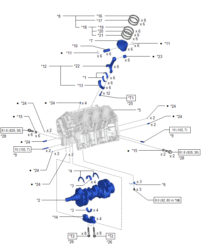
COMPONENTS
ILLUSTRATION
|
*1 | CONNECTING ROD BEARING |
*2 | CRANKSHAFT |
|
*3 | CRANKSHAFT BEARING |
*4 | CRANKSHAFT THRUST WASHER SET |
|
*5 | CYLINDER BLOCK SUB-ASSEMBLY |
*6 | NO. 1 OIL NOZZLE SUB-ASSEMBLY |
|
*7 | PISTON |
*8 | PISTON RING SET |
|
*9 | STUD BOLT |
*10 | PISTON PIN |
|
*11 | PISTON PIN HOLE SNAP RING |
*12 | CONNECTING ROD SUB-ASSEMBLY |
|
*13 | CONNECTING ROD CAP |
*14 | CRANKSHAFT BEARING CAP |
|
*15 | SEAL WASHER |
*16 | NO. 1 COMPRESSION RING |
|
*17 | NO. 2 COMPRESSION RING |
*18 | OIL RING |
|
*19 | UPPER SIDE RAIL |
*20 | OIL RING EXPANDER |
|
*21 | LOWER SIDE RAIL |
*22 | CONNECTING ROD |
|
*23 | CONNECTING ROD SMALL END BUSH |
*24 | STRAIGHT PIN |
|
*25 | CONNECTING ROD BOLT |
*26 | CRANKSHAFT BEARING CAP SET BOLT |
 |
N*m (kgf*cm, ft.*lbf): Specified torque |
● | Non-reusable part |
|
*T1 | 1st: 24.5 (250, 18) 2nd: Turn 90° | *T2 |
1st: 61 (622, 45) 2nd: Turn 90° |
DISASSEMBLY
CAUTION / NOTICE / HINT
The necessary procedures (adjustment, calibration, initialization or registration) that must be performed after parts are removed and installed, or replaced during engine unit removal/installation are shown below.
Necessary Procedure After Parts Removed/Installed/Replaced|
Replaced Part or Performed Procedure |
Necessary Procedure | Effect/Inoperative Function when Necessary Procedure not Performed |
Link |
|---|---|---|---|
|
Battery terminal is disconnected/reconnected |
Perform steering sensor zero point calibration |
Lane departure alert system (w/ Steering Control) |
|
|
Pre-collision system | |||
|
Intelligent Clearance Sonar System*1 | |||
|
Lighting System (for Gasoline Model with Cornering Light) | |||
|
Memorize steering angle neutral point |
Parking Assist Monitor System |
| |
|
Panoramic View Monitor System |
| ||
|
Replacement of ECM | Vehicle Identification Number (VIN) registration |
MIL comes on |
|
|
ECU communication ID registration (Immobiliser system) |
Engine start function |
| |
| Inspection after repair |
|
|
|
Replacement of automatic transaxle assembly |
|
|
|
|
Replacement of ECM (If transaxle compensation code read from ECM) |
| ||
| Replacement of ECM (If transaxle compensation code not read from ECM) |
| ||
| Replacement of automatic transaxle fluid |
ATF thermal degradation estimate reset |
The value of the Data List item "ATF Thermal Degradation Estimate" is not estimated correctly |
|
|
Replacement of ECM | Code registration (Smart Key System (for Start Function)) |
|
|
|
Suspension, tires, etc. |
|
|
|
|
Rear television camera assembly optical axis adjustment (Back camera position setting) |
Parking Assist Monitor System |
| |
| Panoramic View Monitor System |
| |
|
Perform headlight ECU sub-assembly LH initialization |
Lighting system (for Gasoline Model with Cornering Light) |
| |
|
Front wheel alignment adjustment |
Perform system variant learning and acceleration sensor zero point calibration. |
|
|
Click here 
PROCEDURE
1. REMOVE PISTON SUB-ASSEMBLY WITH CONNECTING ROD
(a) Check that the matchmarks on the connecting rod sub-assembly and connecting rod cap are aligned.
HINT:
The matchmarks on the connecting rod sub-assembly and connecting rod cap are guides for correct reassembly.
(b) Remove the 2 connecting rod bolts.
 | Front of Engine |
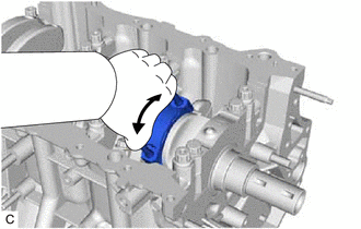
| (c) Using the 2 removed connecting rod bolts, remove the connecting rod cap and lower connecting rod bearing by wiggling the connecting rod cap right and left. HINT: Keep the lower connecting rod bearing installed to the connecting rod cap. |
|
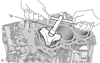
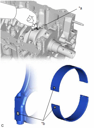
| (d) Using a ridge reamer, remove all of the carbon from the top of the cylinder. |
|
(e) Push the piston, connecting rod sub-assembly and upper connecting rod bearing through the top of the cylinder block sub-assembly.
HINT:
2. REMOVE CONNECTING ROD BEARING
(a) Remove the connecting rod bearings from the connecting rod sub-assembly and connecting rod cap.
HINT:
Arrange the removed parts in such a way that they can be reinstalled to their original locations.
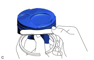
3. REMOVE PISTON RING SET
| (a) Using a piston ring expander, remove the No. 1 compression ring and No. 2 compression ring. |
|
(b) Remove the oil ring expander and 2 side rails by hand.
HINT:
Arrange the removed parts in such a way that they can be reinstalled to their original locations.
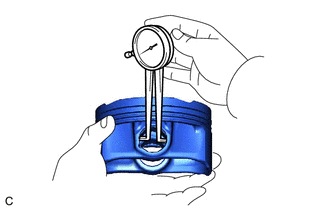
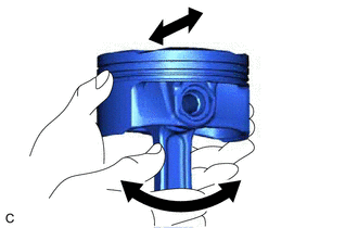
4. REMOVE PISTON
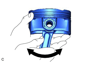
| (a) Check the fitting condition between the piston and piston pin. (1) Try to move the piston back and forth on the piston pin. HINT: If abnormal movement is felt, replace the piston and piston pin as a set. |
|
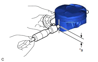
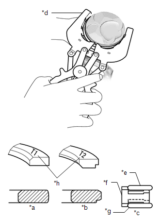
(b) Remove the connecting rod sub-assembly from the piston.
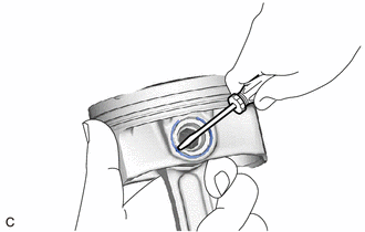
(1) Using a screwdriver, pry out the piston pin hole snap ring (front side).
NOTICE:
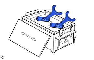
| (2) Gradually heat the piston to approximately 80°C (176°F). CAUTION: Be sure to wear protective gloves. |
|
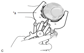
| (3) Using a brass bar and a hammer, lightly tap out the piston pin and remove the connecting rod sub-assembly. HINT:
|
|
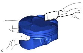
| (c) Using a gasket scraper, remove any carbon from the piston top. NOTICE: Be careful not to scratch the piston. |
|
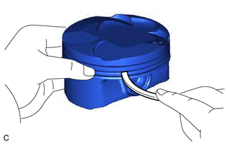
| (d) Using a groove cleaning tool or a broken ring, clean the piston ring grooves. |
|
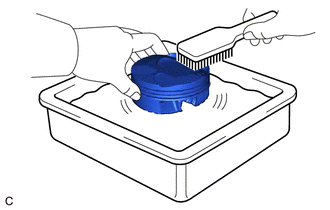
| (e) Using solvent and a brush, thoroughly clean the piston. NOTICE: Do not use a wire brush. |
|
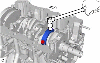
5. REMOVE CRANKSHAFT
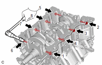
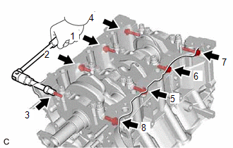
| (a) Uniformly loosen and remove the 8 crankshaft bearing cap set bolts and 8 seal washers in several steps in the order shown in the illustration. |
|
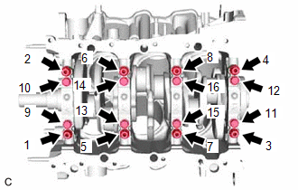
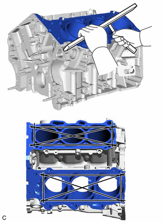
| (b) Uniformly loosen the 16 crankshaft bearing cap set bolts in several steps in the order shown in the illustration. |
|
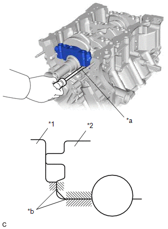
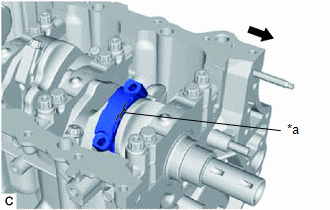
| (c) Using a screwdriver with its tip wrapped with protective tape, pry out the crankshaft bearing caps. Remove the 4 crankshaft bearing caps and 4 lower crankshaft bearings as a set. NOTICE:
|
|
(d) Remove the crankshaft.
6. REMOVE CRANKSHAFT BEARING
(a) Remove the upper crankshaft bearings and lower crankshaft bearings.
HINT:
Arrange the removed parts in such a way that they can be reinstalled to their original locations.
7. REMOVE CRANKSHAFT THRUST WASHER SET
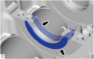
| (a) Remove the crankshaft thrust washer set from the cylinder block sub-assembly. |
|
8. REMOVE NO. 1 OIL NOZZLE SUB-ASSEMBLY
| (a) Using a 5 mm hexagon socket wrench, remove the 3 bolts and 3 No. 1 oil nozzle sub-assemblies. |
|
(b) Check the 3 No. 1 oil nozzle sub-assemblies for damage or clogging.
HINT:
If there is damage or clogs, replace the No. 1 oil nozzle sub-assembly.
INSPECTION
PROCEDURE
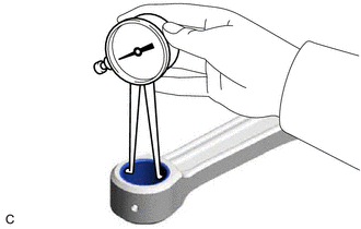
1. INSPECT CONNECTING ROD THRUST CLEARANCE
(a) Install the connecting rod cap.
Click here

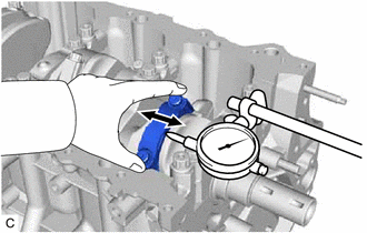
| (b) Using a dial indicator, measure the thrust clearance while moving the connecting rod back and forth. Standard Thrust Clearance: 0.15 to 0.40 mm (0.00591 to 0.0157 in.) Maximum Thrust Clearance: 0.50 mm (0.0197 in.) HINT: If the thrust clearance is more than the maximum, replace the connecting rod sub-assembly. If necessary, replace the crankshaft. |
|
2. INSPECT CONNECTING ROD OIL CLEARANCE
(a) Clean the crank pin and connecting rod bearing.
(b) Check the crank pin and connecting rod bearing for pitting or scratches.
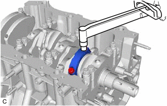
| (c) Lay a strip of Plastigage on the crank pin. |
|
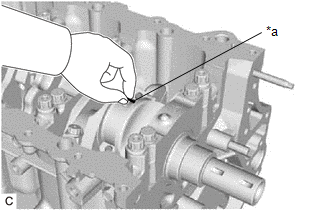
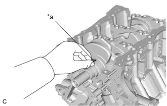
(d) Ensure that the front mark of the connecting rod cap is facing forward.
|
*a | Front Mark |
 |
Front of Engine |
(e) Install the connecting rod cap with the 2 bolts.
Click here
NOTICE:
Do not turn the crankshaft.
(f) Remove the 2 bolts and connecting rod cap.
Click here
| (g) Measure the Plastigage at its widest point. Standard Oil Clearance: 0.045 to 0.067 mm (0.00177 to 0.00264 in.) Maximum Oil Clearance: 0.070 mm (0.00276 in.) HINT:
Standard Connecting Rod Diameter:
Standard Connecting Rod Bearing Center Wall Thickness:
Standard Crankshaft Pin Diameter: 52.992 to 53.000 mm (2.08630 to 2.08661 in.) NOTICE: Completely remove the Plastigage after the measurement. |
|
3. INSPECT CYLINDER BLOCK FOR WARPAGE
| (a) Using a precision straightedge and feeler gauge, check the surfaces which contact the cylinder head gasket for warpage. Maximum Warpage: 0.07 mm (0.00276 in.) HINT: If the warpage is more than the maximum, replace the cylinder block sub-assembly. |
|
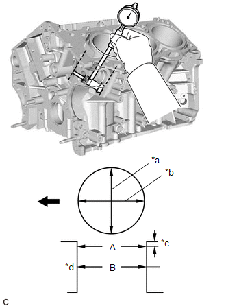
4. INSPECT CYLINDER BORE
(a) Using a cylinder gauge, measure the cylinder bore diameter at the positions (A) and (B) in the thrust and axial directions.
|
*a | Thrust Direction |
|
*b | Axial Direction |
|
*c | 10 mm (0.394 in.) |
|
*d | Center |
|
|
Front of Engine |
Reference Diameter (New Parts):
94.000 to 94.012 mm (3.70078 to 3.70125 in.)
Maximum Diameter:
94.130 mm (3.70590 in.)
HINT:
If the average diameter of 4 positions is more than the maximum, replace the cylinder block sub-assembly.
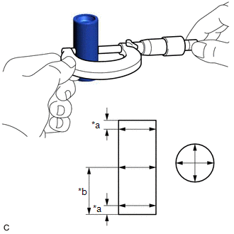
5. INSPECT PISTON
| (a) Using a micrometer, measure the piston diameter at a right angle to the piston center line where the distance from the bottom of the piston is as specified. Distance: 9.2 mm (0.362 in.) Reference Diameter (New Parts): 93.962 to 93.992 mm (3.69928 to 3.70047 in.) Minimum Diameter: 93.830 mm (3.69409 in.) HINT: If the piston diameter is less than the minimum, replace the piston and piston pin as a set. |
|
6. INSPECT PISTON OIL CLEARANCE
(a) Measure the cylinder bore diameter in the thrust direction.
(b) Subtract the piston diameter measurement from the cylinder bore diameter measurement.
Reference Oil Clearance (New Parts):
0.008 to 0.050 mm (0.000315 to 0.00197 in.)
Maximum Oil Clearance:
0.075 mm (0.00295 in.)
HINT:
If the oil clearance is more than the maximum, replace all the pistons. If necessary, replace the cylinder block sub-assembly.
7. INSPECT RING GROOVE CLEARANCE
| (a) Using a feeler gauge, measure the clearance between a new piston ring set and the wall of the ring groove. Standard Ring Groove Clearance:
HINT: If the clearance is not as specified, replace the piston. |
|
8. INSPECT PISTON PIN OIL CLEARANCE
| (a) Using a caliper gauge, measure the inside diameter of the piston pin hole. Standard Piston Pin Hole Inside Diameter:
|
|
| (b) Using a micrometer, measure the piston pin diameter. Standard Piston Pin Diameter:
|
|
(c) Subtract the piston pin diameter measurement from the piston pin hole diameter measurement.
Standard Oil Clearance:
-0.002 to 0.004 mm (-0.0000787 to 0.000157 in.)
Maximum Oil Clearance:
0.015 mm (0.000591 in.)
HINT:
If the oil clearance is more than the maximum, replace the piston and piston pin as a set.
| (d) Using a caliper gauge, measure the inside diameter of the connecting rod small end bush. Standard Bushing Inside Diameter:
|
|
| (e) Subtract the piston pin diameter measurement from the bushing inside diameter measurement. Standard Oil Clearance: 0.005 to 0.011 mm (0.000197 to 0.000433 in.) Maximum Oil Clearance: 0.030 mm (0.00118 in.) HINT:
|
|
9. INSPECT PISTON RING END GAP
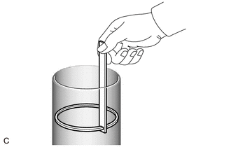
(a) Insert the piston ring into the cylinder bore.
| (b) Using a piston, push in the piston ring slightly beyond the bottom of the ring travel, 110 mm (4.33 in.) from the top of the cylinder block sub-assembly. |
|
| (c) Using a feeler gauge, measure the end gap. Standard End Gap:
Maximum End Gap:
HINT: If the end gap is more than the maximum, replace the piston ring. If the end gap is more than the maximum even with a new piston ring, replace the cylinder block sub-assembly. |
|
10. INSPECT CRANKSHAFT THRUST CLEARANCE
(a) Install the crankshaft bearing caps.
Click here
| (b) Using a dial indicator, measure the thrust clearance while prying the crankshaft back and forth with a screwdriver. Standard Thrust Clearance: 0.04 to 0.24 mm (0.00157 to 0.00945 in.) Maximum Thrust Clearance: 0.30 mm (0.0118 in.) Standard Thrust Washer Thickness: 2.43 to 2.48 mm (0.0957 to 0.0976 in.) HINT: If the thrust clearance is more than the maximum, replace the crankshaft thrust washer set. If necessary, replace the crankshaft. |
|
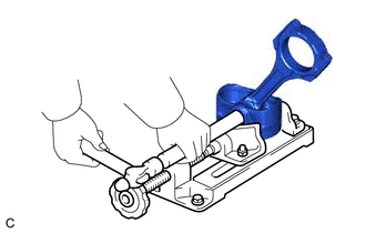
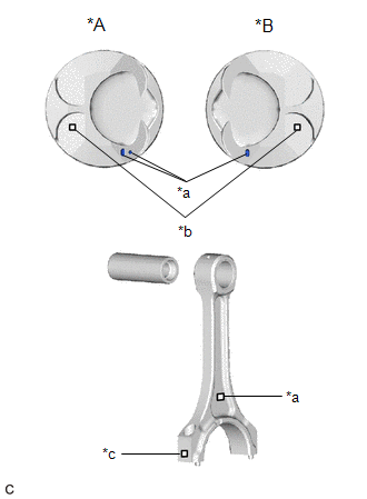
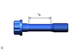
11. INSPECT CONNECTING ROD BOLT
| (a) Using a vernier caliper, measure the diameter of the connecting rod bolt at several points within the area shown in the illustration. Standard Diameter: 7.2 to 7.3 mm (0.283 to 0.287 in.) Minimum Diameter: 7.0 mm (0.276 in.) HINT:
|
|
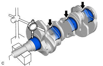
12. INSPECT CRANKSHAFT
(a) Inspect for runout.
(1) Clean the crank journal.
(2) Place the crankshaft on V-blocks.
| (3) Using a dial indicator, measure the runout at the center of each journal. Maximum Runout: 0.06 mm (0.00236 in.) HINT: If the runout is more than the maximum, replace the crankshaft. |
|
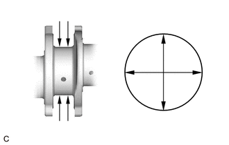
(b) Inspect the main journals.
| (1) Using a micrometer, measure the diameter of each main journal. Standard Journal Diameter: 60.988 to 61.000 mm (2.40110 to 2.40157 in.) HINT: If the diameter is not as specified, check the oil clearance. If necessary, replace the crankshaft. |
|
(2) Check each main journal for taper and out-of-round as shown in the illustration.
Maximum Taper and Out-of-round:
0.02 mm (0.000787 in.)
HINT:
If the taper or out-of-round is more than the maximum, replace the crankshaft.
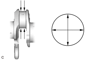
(c) Inspect the crank pins.
| (1) Using a micrometer, measure the diameter of each crank pin. Standard Crank Pin Diameter: 52.992 to 53.000 mm (2.08630 to 2.08661 in.) HINT: If the diameter is not as specified, check the oil clearance. If necessary, replace the crankshaft. |
|
(2) Check each crank pin for taper and out-of-round as shown in the illustration.
Maximum Taper and Out-of-round:
0.02 mm (0.000787 in.)
HINT:
If the taper or out-of-round is more than the maximum, replace the crankshaft.
13. INSPECT CRANKSHAFT OIL CLEARANCE
(a) Check the crank journal and crankshaft bearing for pitting or scratches.
(b) Install the crankshaft bearings.
Click here
(c) Install the crankshaft thrust washer set.
Click here
(d) Place the crankshaft on the cylinder block sub-assembly.
| (e) Lay a strip of Plastigage across each journal. |
|
(f) Confirm the front marks and numbers, and install the crankshaft bearing caps on the cylinder block sub-assembly.
HINT:
A number is marked on each crankshaft bearing cap to indicate its installation position.
(g) Install the crankshaft bearing caps.
Click here
NOTICE:
Do not turn the crankshaft.
(h) Remove the crankshaft bearing caps.
Click here
| (i) Measure the Plastigage at its widest point. Standard Oil Clearance:
Maximum Oil Clearance:
NOTICE: Completely remove the Plastigage after the measurement. HINT: If the oil clearance is more than the maximum, replace the crankshaft bearings. If necessary, replace the crankshaft. |
|
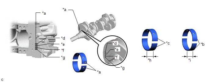
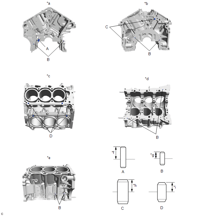
(j) If replacing a crankshaft bearing, select a new one with the same number. If the number of the crankshaft bearing cannot be determined, select the correct crankshaft bearing by adding together the numbers imprinted on the cylinder block sub-assembly and crankshaft. Then refer to the following table for the appropriate crankshaft bearing number. There are 5 sizes of standard crankshaft bearings, marked "1", "2", "3", "4" or "5" accordingly.
|
*a | Number Mark |
*b | No. 2 and No. 3 Crankshaft Bearing |
|
*c | No. 1 and No. 4 Crankshaft Bearing |
*d | No. 1 |
|
*e | No. 2 |
*f | No. 3 |
|
*g | No. 4 |
*h | 20.9 mm (0.823 in.) |
|
*i | 17.9 mm (0.705 in.) |
- | - |
Crankshaft Bearings:
|
Cylinder block sub-assembly+ Crankshaft |
Upper crankshaft bearing to be used |
Lower crankshaft bearing to be used |
|---|---|---|
|
0 to 3 | "1" |
"1" |
| 4 to 6 |
"1" | "2" |
|
7 to 9 | "2" |
"2" |
| 10 to 12 |
"2" | "3" |
|
13 to 15 | "3" |
"3" |
| 16 to 18 |
"3" | "4" |
|
19 to 21 | "4" |
"4" |
| 22 to 24 |
"4" | "5" |
|
25 to 28 | "5" |
"5" |
HINT:
EXAMPLE: Cylinder block sub-assembly "12" + Crankshaft "06" = Total number 18 (Use upper bearing "3" and lower bearing "4")
Crankshaft Main Journal Diameter:
|
Mark | Diameter |
|---|---|
|
"00" | 60.999 to 61.000 mm (2.40153 to 2.40157 in.) |
|
"01" | 60.998 to 60.999 mm (2.40149 to 2.40153 in.) |
|
"02" | 60.997 to 60.998 mm (2.40145 to 2.40149 in.) |
|
"03" | 60.996 to 60.997 mm (2.40141 to 2.40145 in.) |
|
"04" | 60.995 to 60.996 mm (2.40137 to 2.40141 in.) |
|
"05" | 60.994 to 60.995 mm (2.40133 to 2.40137 in.) |
|
"06" | 60.993 to 60.994 mm (2.40129 to 2.40133 in.) |
|
"07" | 60.992 to 60.993 mm (2.40126 to 2.40129 in.) |
|
"08" | 60.991 to 60.992 mm (2.40122 to 2.40126 in.) |
|
"09" | 60.990 to 60.991 mm (2.40118 to 2.40122 in.) |
|
"10" | 60.989 to 60.990 mm (2.40114 to 2.40118 in.) |
|
"11" | 60.988 to 60.989 mm (2.40110 to 2.40114 in.) |
Standard Upper Crankshaft Bearing Center Wall Thickness (No. 1 and No. 4 journal):
|
Mark | Specified Condition |
|---|---|
|
"1" | 2.497 to 2.500 mm (0.09831 to 0.09843 in.) |
|
"2" | 2.501 to 2.503 mm (0.09846 to 0.09854 in.) |
|
"3" | 2.504 to 2.506 mm (0.09858 to 0.09866 in.) |
|
"4" | 2.507 to 2.509 mm (0.09870 to 0.09878 in.) |
|
"5" | 2.510 to 2.512 mm (0.09882 to 0.09890 in.) |
Standard Lower Crankshaft Bearing Center Wall Thickness (No. 1 and No. 4 journal):
|
Mark | Specified Condition |
|---|---|
|
"1" | 2.478 to 2.481 mm (0.09756 to 0.09768 in.) |
|
"2" | 2.482 to 2.484 mm (0.09772 to 0.09780 in.) |
|
"3" | 2.485 to 2.487 mm (0.09783 to 0.09791 in.) |
|
"4" | 2.488 to 2.490 mm (0.09795 to 0.09803 in.) |
|
"5" | 2.491 to 2.493 mm (0.09807 to 0.09815 in.) |
Standard Upper Crankshaft Bearing Center Wall Thickness (No. 2 and No. 3 journal):
|
Mark | Specified Condition |
|---|---|
|
"1" | 2.476 to 2.479 mm (0.09748 to 0.09760 in.) |
|
"2" | 2.480 to 2.482 mm (0.09764 to 0.09772 in.) |
|
"3" | 2.483 to 2.485 mm (0.09776 to 0.09783 in.) |
|
"4" | 2.486 to 2.488 mm (0.09787 to 0.09795 in.) |
|
"5" | 2.489 to 2.491 mm (0.09799 to 0.09807 in.) |
Standard Lower Crankshaft Bearing Center Wall Thickness (No. 2 and No. 3 journal):
|
Mark | Specified Condition |
|---|---|
|
"1" | 2.493 to 2.496 mm (0.09815 to 0.09827 in.) |
|
"2" | 2.497 to 2.499 mm (0.09831 to 0.09839 in.) |
|
"3" | 2.500 to 2.502 mm (0.09843 to 0.09850 in.) |
|
"4" | 2.503 to 2.505 mm (0.09854 to 0.09862 in.) |
|
"5" | 2.506 to 2.508 mm (0.09866 to 0.09874 in.) |
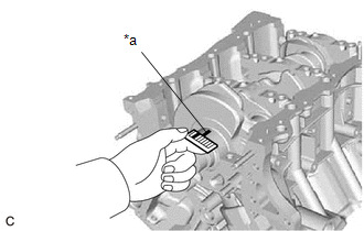
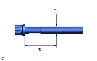
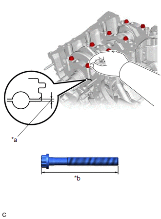
14. INSPECT CRANKSHAFT BEARING CAP SET BOLT
| (a) Using a vernier caliper, measure the diameter of the threads at the measurement point. Standard Diameter: 10.8 to 11.0 mm (0.425 to 0.433 in.) Minimum Diameter: 10.7 mm (0.421 in.) Measurement Point (Distance from the Seat): 40 mm (1.57 in.) HINT:
|
|
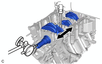
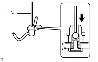
15. INSPECT NO. 1 OIL NOZZLE SUB-ASSEMBLY
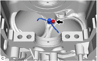
| (a) Push the check valve with a pin to check that it is not stuck. HINT: If the check valve is stuck, replace the No. 1 oil nozzle sub-assembly. |
|
(b) Push the check valve with a pin to check if it moves smoothly.
HINT:
If the check valve does not move smoothly, clean or replace the No. 1 oil nozzle sub-assembly.
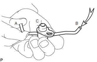
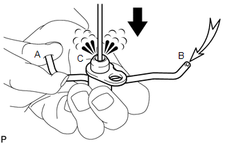
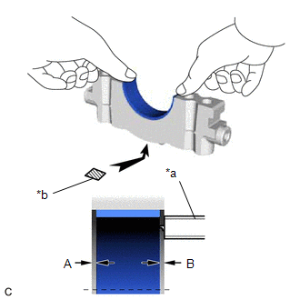
| (c) While covering (A), blow air into (B). Check that air does not leak through (C). Perform the check again while covering (B) and blowing air into (A). HINT: If air leaks, clean or replace the No. 1 oil nozzle sub-assembly. |
|
| (d) Push the check valve while covering (A), and blow air into (B). Check that air passes through (C). Perform the check again while covering (B), pushing the check valve and blowing air into (A). HINT: If air does not pass through (C), clean or replace the No. 1 oil nozzle sub-assembly. |
|
PRECAUTION
HINT:
REASSEMBLY
PROCEDURE
1. INSTALL NO. 1 OIL NOZZLE SUB-ASSEMBLY
| (a) Using a 5 mm hexagon socket wrench, install the 3 No. 1 oil nozzle sub-assemblies to the cylinder block sub-assembly with the 3 bolts. Torque: 9.0 N·m {92 kgf·cm, 80 in·lbf} |
|
2. INSTALL PISTON
HINT:
Perform this procedure only when replacement of the piston pin hole snap ring (rear side) is necessary.
(a) Using a screwdriver, install a new piston pin hole snap ring (rear side) at one end of the piston pin hole.
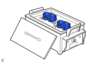
| (b) Gradually heat the piston to approximately 80°C (176°F). |
|
(c) Coat the piston pin with engine oil.
CAUTION:
Be sure to wear protective gloves.
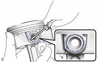
| (d) Align the front marks of the piston and connecting rod sub-assembly, and push in the piston pin with your thumb. HINT: The piston and piston pin are a matched set. |
|
| (e) Using a screwdriver, install a new piston pin hole snap ring at the other end of the piston pin hole. NOTICE: Make sure that the end gap of the piston pin hole snap ring is not aligned with the cutout of the piston pin hole. |
|
| (f) Check the fitting condition between the piston and piston pin. (1) Move the connecting rod back and forth on the piston pin. Check the fitting condition. HINT: If abnormal movement is felt, replace the piston and piston pin as a set. (2) Rotate the piston back and forth on the piston pin. Check the fitting condition. HINT:
|
|
3. INSTALL PISTON RING SET
(a) Install the oil ring expander and 2 side rails by hand.
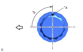
| (b) Using a piston ring expander, install the No. 1 compression ring and No. 2 compression ring as shown in the illustration. NOTICE:
|
|
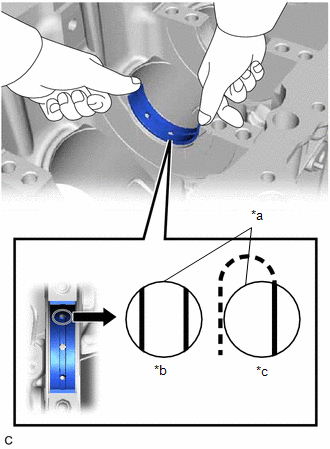
| (c) Position the piston ring set so that the ring ends are as shown in the illustration. NOTICE: Do not align the ring ends. HINT: Perform Inspection After Repair after replacing the piston ring. Click here |
|
4. INSTALL CRANKSHAFT BEARING
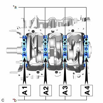
| (a) Clean the main journals and both surfaces of the crankshaft bearings. NOTICE: Crankshaft bearings come in widths of 17.9 mm (0.705 in.) and 20.9 mm (0.823 in.). Install the 20.9 mm (0.823 in.) crankshaft bearings to the No. 1 and No. 4 cylinder block journal positions. Install the 17.9 mm (0.705 in.) crankshaft bearings to the No. 2 and No. 3 positions. |
|
| (b) Install the upper crankshaft bearings. (1) Install the upper crankshaft bearings to the cylinder block sub-assembly as shown in the illustration. NOTICE:
|
|
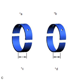
| (c) Install the lower crankshaft bearings. (1) Install the lower crankshaft bearings to the crankshaft bearing caps. (2) Using a vernier caliper, measure the distance between the crankshaft bearing cap edge and lower crankshaft bearing edge. Difference Between (A) and (B): 0.7 mm (0.0276 in.) or less NOTICE:
|
|
5. INSTALL CRANKSHAFT THRUST WASHER SET
(a) Apply engine oil to the crankshaft thrust washer set.
| (b) Install the crankshaft thrust washer set under the No. 2 journal position of the cylinder block sub-assembly with the oil grooves facing outward. |
|
6. INSTALL CRANKSHAFT
(a) Apply engine oil to the crankshaft bearings, then place the crankshaft on the cylinder block sub-assembly.
| (b) Confirm the projections and numbers of the crankshaft bearing caps and install the 4 crankshaft bearing caps to the cylinder block sub-assembly. HINT: A number is marked on each crankshaft bearing cap to indicate its installation position. |
|
(c) Apply a light coat of engine oil to the threads and under the heads of the crankshaft bearing cap set bolts.
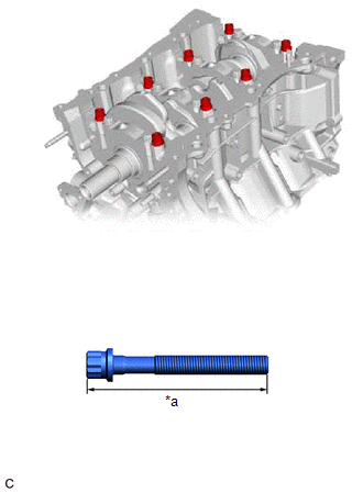
| (d) Temporarily install the 8 crankshaft bearing cap set bolts to the inside positions. Bolt Length: 100 to 102 mm (3.94 to 4.02 in.) |
|
(e) Push the crankshaft bearing cap with your hand until the clearance between the crankshaft bearing cap and the cylinder block sub-assembly is less than 6 mm (0.236 in.) by using the 2 inside crankshaft bearing cap set bolts as a guide.
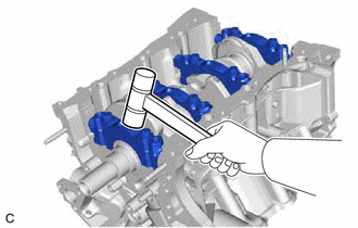
|
(f) Using a plastic hammer, lightly tap the crankshaft bearing cap to ensure a proper fit. |
|
(g) Apply a light coat of engine oil to the threads and under the heads of the 8 crankshaft bearing cap set bolts.
| (h) Temporarily install the 8 crankshaft bearing cap set bolts to the outside positions. Bolt Length: 105.5 to 107.5 mm (4.15 to 4.23 in.) |
|
(i) Install the crankshaft bearing cap set bolts.
HINT:
The crankshaft bearing cap set bolts are tightened in 2 progressive steps.
(j) Step 1:
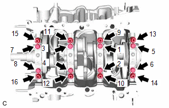
| (1) Uniformly tighten the 16 crankshaft bearing cap set bolts in several steps in the order shown in the illustration. Torque: 61 N·m {622 kgf·cm, 45 ft·lbf} HINT: If a crankshaft bearing cap bolt cannot be tightened to the specified torque, replace it. |
|
(k) Step 2:
(1) Mark the front of the crankshaft bearing cap set bolts with paint.
|
*a | Paint Mark |
|
*b | Turn 90° |
 |
Front of Engine |
(2) Tighten the crankshaft bearing cap set bolts 90° in the order shown in the illustration.
(3) Check that the paint marks are now at a 90° angle to the front.
| (l) Install 8 new seal washers and uniformly tighten the 8 crankshaft bearing cap set bolts in several steps in the order shown in the illustration. Torque: 51.5 N·m {525 kgf·cm, 38 ft·lbf} |
|
(m) Check that the crankshaft turns smoothly.
(n) Check the crankshaft thrust clearance.
Click here 
7. INSTALL CONNECTING ROD BEARING
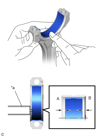
(a) Install the connecting rod bearings to the connecting rod sub-assembly and connecting rod cap.
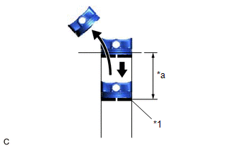
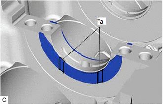
| (b) Using a vernier caliper, measure the distance between the connecting rod sub-assembly, connecting rod cap edges and the connecting rod bearing edge. Difference Between (A) and (B): 0.7 mm (0.0276 in.) or less NOTICE: Do not apply engine oil to the connecting rod bearings or the contact surfaces. |
|
8. INSTALL PISTON SUB-ASSEMBLY WITH CONNECTING ROD
(a) Apply engine oil to the cylinder walls, the pistons, and the surfaces of the connecting rod bearings.
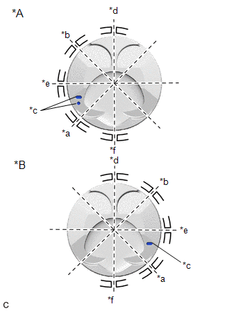
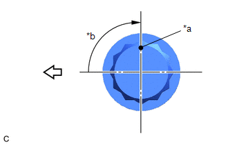
| (b) Position the piston ring set so that the ring ends are as shown in the illustration. NOTICE: Do not align the ring ends. |
|
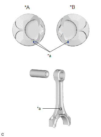
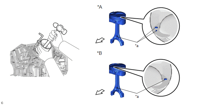
(c) Using a piston ring compressor, push the piston and connecting rod sub-assembly into the cylinder with the front mark of the piston facing the front of the engine.
|
*A | for Bank 1 |
*B | for Bank 2 |
|
*a | Front Mark |
- | - |
|
|
Front of Engine | - |
- |
NOTICE:
Match the connecting rod cap with the connecting rod sub-assembly.
(d) Check that the front mark of the connecting rod cap is facing the front of the engine.
|
*a | Front Mark |
|
|
Front of Engine |
(e) Apply a light coat of engine oil to the threads and under the heads of the connecting rod bolts.
(f) Install the 2 connecting rod bolts.
HINT:
The connecting rod bolts are tightened in 2 progressive steps.
(g) Step 1:
| (1) Alternately tighten the 2 connecting rod bolts in several steps. Torque: 24.5 N·m {250 kgf·cm, 18 ft·lbf} |
|
(h) Step 2:
|
*a | Paint Mark |
|
*b | Turn 90° |
|
|
Front of Engine |
(1) Mark the front of each connecting rod bolt with paint.
(2) Further tighten the connecting rod bolts 90° as shown in the illustration.
(3) Check that the paint marks are now at a 90° angle to the front.
(i) Confirm that the crankshaft turns smoothly.
(j) Check the connecting rod thrust clearance.
Click here
REPLACEMENT
PROCEDURE
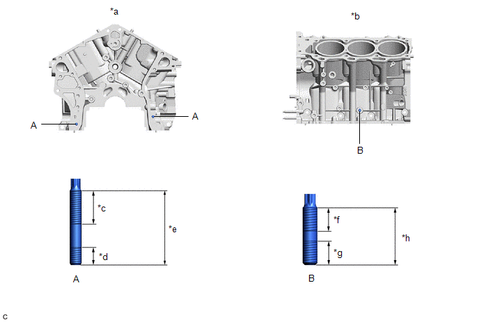
1. REPLACE STRAIGHT PIN
NOTICE:
If a straight pin is deformed, replace it.
(a) Using a plastic hammer, tap in new straight pins to the cylinder block sub-assembly.
|
*a | Front Side |
*b | Rear Side |
|
*c | Top Side |
*d | Bottom Side |
|
*e | RH Side |
*f | 23 mm (0.906 in.) |
|
*g | 6 mm (0.236 in.) |
*h | 11 mm (0.433 in.) |
|
*i | 9 mm (0.354 in.) |
- | - |
Standard Protrusion Height:
|
Item | Specified Condition |
|---|---|
|
Pin (A) | 23 mm (0.906 in.) |
|
Pin (B) | 6 mm (0.236 in.) |
|
Pin (C) | 11 mm (0.433 in.) |
|
Pin (D) | 9 mm (0.354 in.) |
2. REPLACE STUD BOLT
NOTICE:
If a stud bolt is deformed or its threads are damaged, replace it.
(a) Using E8 and E10 "TORX" socket wrenches, install the stud bolts to the cylinder block sub-assembly.
|
*a | Front Side |
*b | LH Side |
|
*c | 24 mm (0.9449 in.) |
*d | 12 mm (0.4724 in.) |
|
*e | 52 mm (2.05 in.) |
*f | 23 mm (0.906 in.) |
|
*g | 15 mm (0.591 in.) |
*h | 40 mm (1.57 in.) |
Torque:
10 N·m {102 kgf·cm, 7 ft·lbf}
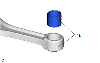
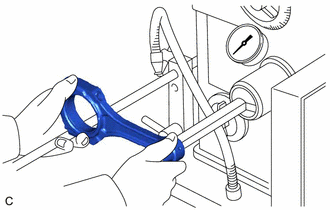
3. REPLACE CONNECTING ROD SMALL END BUSH
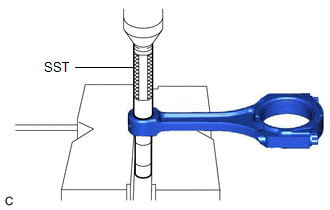
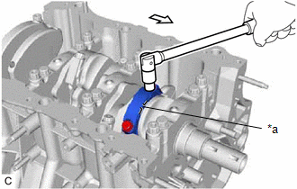
| (a) Using SST and a press, press out the connecting rod small end bush. SST: 09222-30010 |
|
| (b) Align the oil hole of a new connecting rod small end bush with the oil hole of the connecting rod. |
|
| (c) Using SST and a press, push in the connecting rod small end bush. SST: 09222-30010 |
|
| (d) Using a pin hole grinder, hone the connecting rod small end bush to obtain the standard oil clearance between the connecting rod small end bush and piston pin. Standard Oil Clearance: 0.005 to 0.011 mm (0.000197 to 0.000433 in.) |
|
(e) Coat the piston pin with engine oil, and push it into the connecting rod with your thumb.
HINT:
Check that the piston pin fits at a normal room temperature.
Toyota Avalon (XX50) 2019-2022 Service & Repair Manual > Electronically Controlled Brake System(for Hv Model): VSC does not Operate or VSC does not Operate Correctly. VSC OFF Switch Circuit
VSC does not Operate or VSC does not Operate Correctly DESCRIPTION When ABS, TRAC or VSC is operating, the skid control ECU (brake booster with master cylinder assembly) blinks the slip indicator light to inform the driver that slippage occurred. When a communication malfunction with the hybrid vehi ...