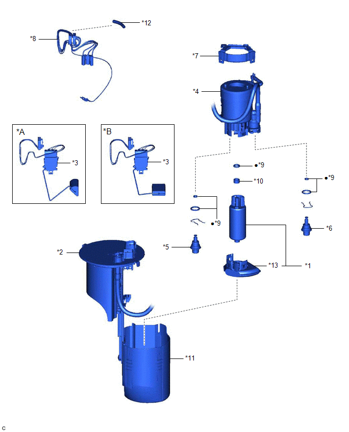
COMPONENTS
ILLUSTRATION
|
*A | Type A |
*B | Type B |
|
*1 | FUEL PUMP |
*2 | FUEL SUCTION PLATE SUB-ASSEMBLY |
|
*3 | FUEL SENDER GAUGE ASSEMBLY |
*4 | FUEL FILTER |
|
*5 | FUEL MAIN VALVE ASSEMBLY (for Low Pressure) |
*6 | FUEL MAIN VALVE ASSEMBLY (for High Pressure) |
|
*7 | NO. 1 FUEL SUCTION SUPPORT |
*8 | FUEL PUMP HARNESS |
|
*9 | O-RING |
*10 | FUEL PUMP SPACER |
|
*11 | FUEL SUB-TANK |
*12 | HARNESS PROTECTOR |
|
*13 | SUCTION FILTER |
- | - |
|
● | Non-reusable part |
- | - |
REPLACEMENT
CAUTION / NOTICE / HINT
The necessary procedures (adjustment, calibration, initialization or registration) that must be performed after parts are removed and installed, or replaced during fuel filter removal/installation are shown below.
Necessary Procedures After Parts Removed/Installed/Replaced|
Replaced Part or Performed Procedure |
Necessary Procedure | Effect/Inoperative Function when Necessary Procedure not Performed |
Link |
|---|---|---|---|
|
*: When performing learning using the Techstream.
Click here | |||
|
Battery terminal is disconnected/reconnected |
Perform steering sensor zero point calibration |
Lane Departure Alert System (w/ Steering Control) |
|
|
Pre-collision System | |||
|
Intelligent Clearance Sonar System* | |||
|
Lighting System (for Gasoline Model with Cornering Light) | |||
|
Memorize steering angle neutral point |
Parking Assist Monitor System |
| |
|
Panoramic View Monitor System |
| ||
|
Replacement of fuel pump |
Inspection after repair |
|
|
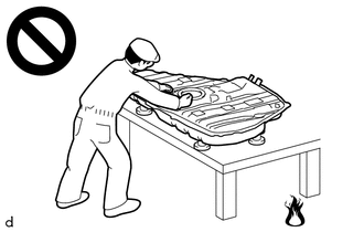
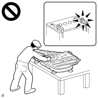
CAUTION:
PROCEDURE
1. REMOVE FUEL SUCTION TUBE WITH PUMP AND GAUGE ASSEMBLY
Click here 
2. REMOVE FUEL SENDER GAUGE ASSEMBLY
Click here
3. REMOVE FUEL PUMP
Click here
4. REMOVE FUEL MAIN VALVE ASSEMBLY
Click here
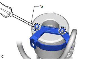
5. REMOVE NO. 1 FUEL SUCTION SUPPORT
| (a) Using a screwdriver with its tip wrapped with protective tape, disengage the 2 claws and remove the No. 1 fuel suction support from the fuel filter. |
|
6. INSTALL NO. 1 FUEL SUCTION SUPPORT
(a) Engage the 2 claws to install the No. 1 fuel suction support to the fuel filter.
7. INSTALL FUEL MAIN VALVE ASSEMBLY
Click here
8. INSTALL FUEL PUMP
Click here
9. INSTALL FUEL SENDER GAUGE ASSEMBLY
Click here
10. INSTALL FUEL SUCTION TUBE WITH PUMP AND GAUGE ASSEMBLY
Click here
Toyota Avalon (XX50) 2019-2022 Service & Repair Manual > Brake System (other): Brake Master Cylinder(for Gasoline Model)
Components COMPONENTS ILLUSTRATION *1 BRAKE MASTER CYLINDER O-RING *2 BRAKE MASTER CYLINDER SUB-ASSEMBLY *3 BRAKE LINE *4 CONNECTOR *5 BRAKE BOOSTER ASSEMBLY - - Tightening torque for "Major areas involving basic vehicle performance such as moving/turning/stopping" : N*m (kgf*cm, ft.*lbf) * For use ...