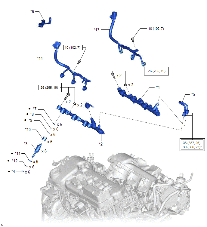
COMPONENTS
ILLUSTRATION
|
*1 | FUEL DELIVERY PIPE RH |
*2 | FUEL DELIVERY PIPE WITH SENSOR ASSEMBLY LH |
|
*3 | FUEL INJECTOR ASSEMBLY |
*4 | FUEL INJECTOR SEAL |
|
*5 | NO. 2 FUEL PIPE SUB-ASSEMBLY |
*6 | WIRE HARNESS CLAMP BRACKET |
|
*7 | NO. 3 FUEL INJECTOR BACK-UP RING |
*8 | O-RING |
|
*9 | NO. 1 FUEL INJECTOR BACK-UP RING |
*10 | NOZZLE HOLDER CLAMP |
|
*11 | INJECTOR VIBRATION INSULATOR |
*12 | C-RING |
|
*13 | NO. 6 ENGINE WIRE |
*14 | NO. 7 ENGINE WIRE |
 |
Tightening torque for "Major areas involving basic vehicle performance such as moving/turning/stopping": N*m (kgf*cm, ft.*lbf) |
 |
N*m (kgf*cm, ft.*lbf): Specified torque |
|
* | For use with a union nut wrench |
● | Non-reusable part |
INSPECTION
PROCEDURE
1. INSPECT FUEL INJECTOR ASSEMBLY
NOTICE:
This inspection is for checking the fuel injector assembly for an open or short. Because the fuel injector assembly of this vehicle is a high-pressure type, fuel injection volume cannot be checked.
| (a) Measure the resistance according to the value(s) in the table below. Standard Resistance:
If the result is not as specified, replace the fuel injector assembly. |
|
INSTALLATION
PROCEDURE
1. INSTALL FUEL INJECTOR SEAL
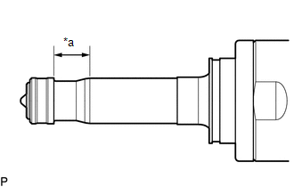
| (a) Apply engine conditioner to the area shown in the illustration. Using a piece of cloth, clean carbon deposits from the fuel injector assembly and its grooves. NOTICE:
|
|
| (b) Apply engine oil to the fuel injector assembly contact surface of SST (guide), then attach SST (guide) to the fuel injector assembly with the chamfer facing the tip of the fuel injector assembly as shown in the illustration. SST: 09260-39021 09261-03020 |
|
| (c) Install a new fuel injector seal to SST (holder). SST: 09260-39021 09261-03011 NOTICE: Be careful not to install the fuel injector seal to SST (holder) at an angle. Doing so will stretch the fuel injector seal. |
|
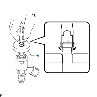
| (d) Install SST (holder) with the fuel injector seal to the tip of the fuel injector assembly. Slide the fuel injector seal downward into the fuel injector assembly groove with your fingers as shown in the illustration. SST: 09260-39021 09261-03011 09261-03020 HINT: Check that the fuel injector seal is seated in the fuel injector assembly groove as shown in the illustration. |
|
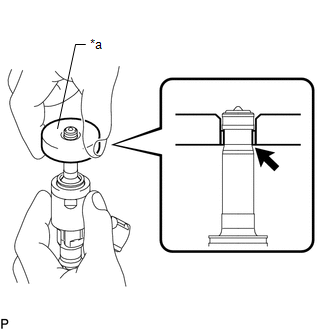
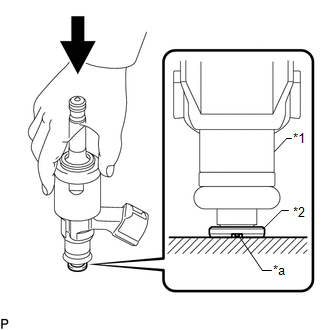
| (e) Slowly slide SST (guide) toward the tip of the fuel injector assembly. When the fuel injector assembly contact surface of SST (guide) aligns with the fuel injector seal as shown in the illustration, hold the position for 5 seconds or more to fully seat the fuel injector seal into the fuel injector assembly groove. SST: 09260-39021 09261-03020 NOTICE: Make sure the fuel injector seal is not pinched between SST (guide) and the edge of the fuel injector assembly groove. Replace the fuel injector seal if it becomes damaged. HINT:
|
|
| (f) After installing the fuel injector seals, check that they are not scratched, deformed or protruding from the fuel injector assembly groove. NOTICE: If a fuel injector seal is scratched, deformed or protruding from the groove, replace it with a new one. HINT: Use the same procedure to install the other fuel injector seals. |
|
2. INSTALL FUEL INJECTOR ASSEMBLY
HINT:
Perform "Inspection After Repair" after replacing a fuel injector assembly.
Click here 
| (a) Install a new injector vibration insulator and a new C-ring to each fuel injector assembly. NOTICE:
|
|
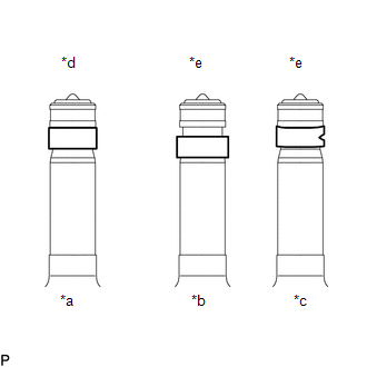
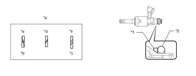
(b) Install a new O-ring and a new No. 1 fuel injector back-up ring to each fuel injector assembly as shown in the illustration.
|
*1 | No. 1 Fuel Injector Back-up Ring |
*2 | O-ring |
|
*a | No. 1 Fuel Injector Back-up Ring Opening |
*b | Overlapped |
|
*c | Stretched |
*d | Correct |
|
*e | Incorrect |
- | - |
NOTICE:
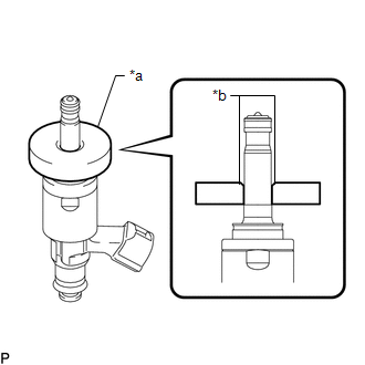
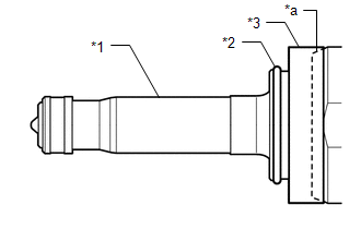
| (c) With the notch of a new No. 3 fuel injector back-up ring facing downward, install the No. 3 fuel injector back-up ring to each fuel injector assembly as shown in the illustration. NOTICE:
|
|
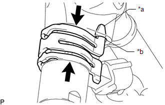
(d) Install the nozzle holder clamp to each fuel injector assembly.
(e) Align the protrusion of the nozzle holder clamp with the positioning hole of the fuel delivery pipe with sensor assembly LH and fuel delivery pipe RH, and insert the fuel injector assembly.
|
*a | Protrusion |
|
*b | Positioning Hole |
 |
No Gap |
NOTICE:
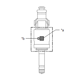
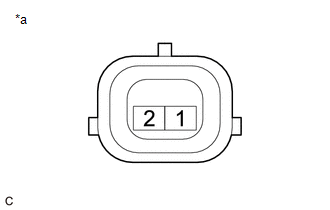
|
*a |
QR Code |
|
*b |
Flow Classification Number |
3. INSTALL FUEL DELIVERY PIPE RH
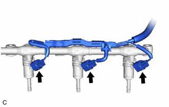
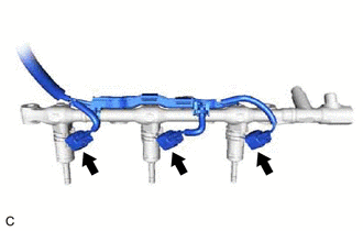
(a) Connect the 3 fuel injector assembly connectors.
(b) Apply lubricant to the fuel injector assembly installation holes of the cylinder head sub-assembly.
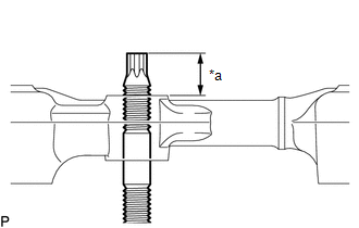
| (c) Temporarily install the fuel delivery pipe RH to the cylinder head sub-assembly so that the stud bolts protrude enough to install the nuts. NOTICE:
|
|
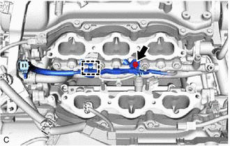
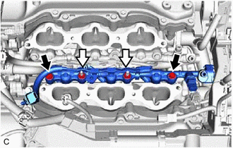
(d) Install the fuel delivery pipe RH by uniformly tightening the 2 bolts and 2 nuts in the order shown in the illustration.
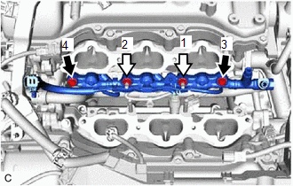
|
| Bolt |
 |
Nut |
Torque:
26 N·m {265 kgf·cm, 19 ft·lbf}
(e) Engage the clamp to connect the No. 6 engine wire to the fuel delivery pipe RH.
(f) Install the bolt.
Torque:
10 N·m {102 kgf·cm, 7 ft·lbf}
4. INSTALL FUEL DELIVERY PIPE WITH SENSOR ASSEMBLY LH
(a) Connect the 3 fuel injector assembly connectors.
(b) Apply lubricant to the fuel injector assembly installation holes of the cylinder head LH.
| (c) Temporarily install the fuel delivery pipe with sensor assembly LH to the cylinder head LH so that the stud bolts protrude enough to install the nuts. NOTICE:
|
|
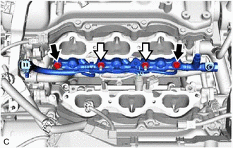
(d) Install the fuel delivery pipe with sensor assembly LH by uniformly tightening the 2 bolts and 2 nuts in the order shown in the illustration.
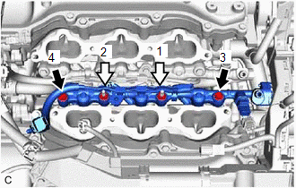
|
| Bolt |
|
|
Nut |
Torque:
26 N·m {265 kgf·cm, 19 ft·lbf}
(e) Engage the clamp to connect the No. 7 engine wire to the fuel delivery pipe with sensor assembly LH.
(f) Install the bolt.
Torque:
10 N·m {102 kgf·cm, 7 ft·lbf}
(g) Connect the fuel pressure sensor connector.
5. INSTALL WIRE HARNESS CLAMP BRACKET
(a) Engage the 2 clamps to install the wire harness clamp bracket.
(b) Connect the No. 6 engine wire connector and No. 7 engine wire connector.
6. INSTALL NO. 2 FUEL PIPE SUB-ASSEMBLY
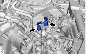
(a) Temporarily install the No. 2 fuel pipe sub-assembly to the fuel delivery pipe with sensor assembly LH and fuel delivery pipe RH and tighten the 2 union nuts by hand.
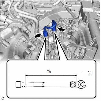
| (b) Using a 17 mm union nut wrench, tighten the 2 union nuts of the No. 2 fuel pipe sub-assembly. Torque: Specified tightening torque : 35 N·m {357 kgf·cm, 26 ft·lbf} NOTICE:
HINT:
|
|
7. INSTALL FUEL PUMP ASSEMBLY (for High Pressure)
Click here
8. PERFORM INITIALIZATION
(a) Perform "Inspection After Repair" after replacing a fuel injector assembly.
Click here
REMOVAL
CAUTION / NOTICE / HINT
The necessary procedures (adjustment, calibration, initialization or registration) that must be performed after parts are removed and installed, or replaced during fuel injector assembly removal/installation are shown below.
Necessary Procedures After Parts Removed/Installed/Replaced|
Replaced Part or Performed Procedure |
Necessary Procedure | Effect/Inoperative Function when Necessary Procedure not Performed |
Link |
|---|---|---|---|
|
*: When performing learning using the Techstream.
Click here | |||
|
Battery terminal is disconnected/reconnected |
Perform steering sensor zero point calibration |
Lane Departure Alert System (w/ Steering Control) |
|
|
Pre-collision System | |||
|
Intelligent Clearance Sonar System* | |||
|
Lighting System (for Gasoline Model with Cornering Light) | |||
|
Memorize steering angle neutral point |
Parking Assist Monitor System |
| |
|
Panoramic View Monitor System |
| ||
| Inspection after repair |
|
|
CAUTION:
PROCEDURE
1. REMOVE FUEL PUMP ASSEMBLY (for High Pressure)
Click here 
2. REMOVE NO. 2 FUEL PIPE SUB-ASSEMBLY
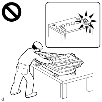
CAUTION:
To prevent serious injury due to fuel spray from the high-pressure fuel lines, always discharge fuel system pressure before removing any fuel system components.
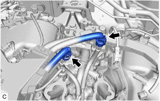
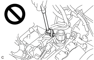
| (a) Using a 17 mm union nut wrench, loosen the 2 union nuts of the No. 2 fuel pipe sub-assembly. |
|
(b) Remove the No. 2 fuel pipe sub-assembly from the fuel delivery pipe with sensor assembly LH and fuel delivery pipe RH.
3. REMOVE WIRE HARNESS CLAMP BRACKET
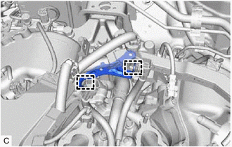
| (a) Disconnect the No. 6 engine wire connector and No. 7 engine wire connector. |
|
| (b) Disengage the 2 clamps to remove the wire harness clamp bracket. |
|
4. REMOVE FUEL DELIVERY PIPE WITH SENSOR ASSEMBLY LH
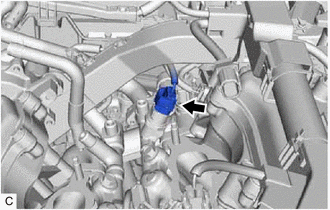
| (a) Disconnect the fuel pressure sensor connector. |
|
| (b) Remove the bolt. |
|
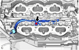
(c) Disengage the clamp to disconnect the No. 7 engine wire from the fuel delivery pipe with sensor assembly LH.
(d) Remove the 2 bolts, 2 nuts and fuel delivery pipe with sensor assembly LH with the 3 fuel injector assemblies from the cylinder head LH.
 |
Bolt |
 |
Nut |
NOTICE:
| (e) Disconnect the 3 fuel injector assembly connectors. |
|
5. REMOVE FUEL DELIVERY PIPE RH
| (a) Remove the bolt. |
|
(b) Disengage the clamp to disconnect the No. 6 engine wire from the fuel delivery pipe RH.
(c) Remove the 2 bolts, 2 nuts and fuel delivery pipe RH with the 3 fuel injector assemblies from the cylinder head sub-assembly.
|
|
Bolt |
|
|
Nut |
NOTICE:
| (d) Disconnect the 3 fuel injector assembly connectors. |
|
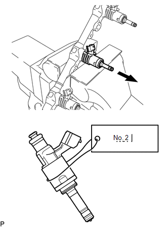
6. REMOVE FUEL INJECTOR ASSEMBLY
| (a) Secure the fuel delivery pipe with sensor assembly LH and fuel delivery pipe RH in a vise between aluminum plates and pull out the 6 fuel injector assemblies. NOTICE:
|
|
(b) Remove the nozzle holder clamp from each fuel injector assembly.
(c) Using needle nose pliers, remove the No. 3 fuel injector back-up ring from each fuel injector assembly.
NOTICE:
Do not damage the area that contacts the O-ring.
(d) Remove the O-ring and No. 1 fuel injector back-up ring from each fuel injector assembly.
(e) Remove the C-ring and injector vibration insulator from each fuel injector assembly.
7. REMOVE FUEL INJECTOR SEAL
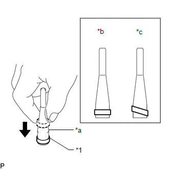
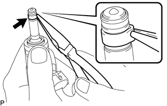
| (a) Using the tip of needle nose pliers, pinch and pull the fuel injector seal at several points to stretch it. NOTICE:
|
|
(b) Remove the fuel injector seal from each fuel injector assembly.
Toyota Avalon (XX50) 2019-2022 Service & Repair Manual > Wiper / Washer: Washer Motor
ComponentsCOMPONENTS ILLUSTRATION *1 FRONT FENDER SPLASH SHIELD SUB-ASSEMBLY RH *2 FRONT WHEEL OPENING EXTENSION PAD RH *3 WINDSHIELD WASHER MOTOR AND PUMP ASSEMBLY - - InspectionINSPECTION PROCEDURE 1. INSPECT WINDSHIELD WASHER MOTOR AND PUMP ASSEMBLY *a Component without harness connected (Windsh ...