COMPONENTS
ILLUSTRATION
|
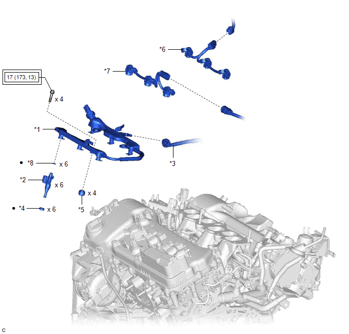
*1 | FUEL DELIVERY PIPE WITH SENSOR ASSEMBLY |
*2 | FUEL INJECTOR ASSEMBLY |
|
*3 | FUEL TUBE SUB-ASSEMBLY |
*4 | INJECTOR VIBRATION INSULATOR |
|
*5 | NO. 1 DELIVERY PIPE SPACER |
*6 | NO. 5 ENGINE WIRE (for Bank 1) |
|
*7 | NO. 5 ENGINE WIRE (for Bank 2) |
*8 | O-RING |
 |
Tightening torque for "Major areas involving basic vehicle performance such as moving/turning/stopping": N*m (kgf*cm, ft.*lbf) |
● | Non-reusable part |
INSPECTION
PROCEDURE
1. INSPECT FUEL INJECTOR ASSEMBLY
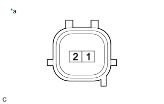
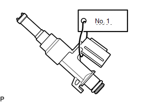
(a) Check the resistance.
| (1) Measure the resistance according to the value(s) in the table below. Standard Resistance:
If the result is not as specified, replace the fuel injector assembly. |
|
(b) Check the operation.
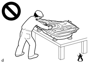
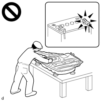
CAUTION:
Perform the inspection in a well-ventilated area.
Do not perform the inspection near an open flame.
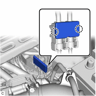
| (1) Disengage the 2 claws to remove the No. 2 fuel pipe clamp. |
|
| (2) Remove the No. 1 fuel pipe clamp from the fuel tube connector. |
|
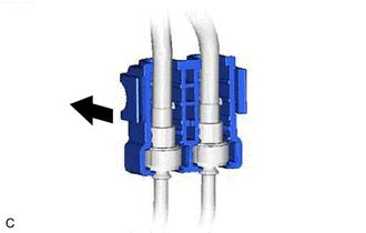
| (3) Disconnect the fuel tube sub-assembly. Click here
|
|
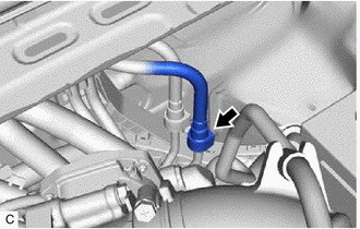
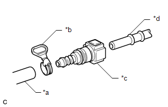
| (4) Connect SST (fuel tube connector) to SST (hose) with SST (hose band), and then connect them to the fuel pipe (vehicle side). SST: 09268-31015 09268-41500 09268-41700 95336-08070 NOTICE: Make sure the SST (fuel tube connector) O-rings are not damaged and are free of foreign matter as they are used to seal the connections between the fuel tube connector and fuel pipe. |
|
(5) Apply a light coat of gasoline to a new O-ring, and then install the O-ring to the fuel injector assembly.
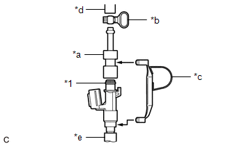
| (6) Connect SST (adapter) and SST (hose) to the fuel injector assembly, and hold the fuel injector assembly and union with SST (clamp). SST: 09268-31015 09268-41600 09268-41300 09268-41700 95336-08070 |
|
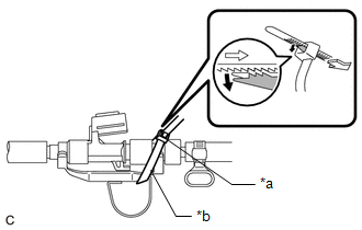
| (7) Tie SST (clamp) and SST (adapter) together with SST (tie band) as shown in the illustration. SST: 09268-31015 09268-41800 NOTICE:
HINT: When removing SST (tie band), disengage the lock. |
|
(8) Check that SST (clamp) and SST (adapter) cannot be easily separated.
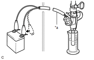
(9) Install a vinyl tube to the fuel injector assembly.
CAUTION:
Install a suitable vinyl tube to the fuel injector assembly to prevent fuel from spraying.
(10) Set the fuel injector assembly into a graduated cylinder.
(11) Connect the Techstream to the DLC3.
(12) Turn the engine switch on (IG).
NOTICE:
Do not start the engine.
(13) Turn the Techstream on.
(14) Enter the following menus: Powertrain / Engine / Active Test / Activate the Circuit Relay.
Powertrain > Engine > Active Test|
Tester Display |
|---|
| Activate the Circuit Relay |
| (15) Connect SST (EFI inspection wire I) to the fuel injector assembly and battery for 15 seconds, and measure the injection volume with the graduated cylinder. Test each fuel injector assembly 2 or 3 times. SST: 09842-30090 Standard Injection Volume:
Difference between Each Fuel Injector Assembly: 14 cc (0.9 cu. in.) or less NOTICE:
If the injection volume is not as specified, replace the fuel injector assembly. |
|
(16) Turn the engine switch off.
(17) Disconnect the Techstream from the DLC3.
(c) Check for leaks.
(1) Disconnect SST (EFI inspection wire I) from the battery and check for fuel leaks from the fuel injector assembly.
Standard Fuel Drop:
1 drop or less per 20 minutes
If the result is not as specified, replace the fuel injector assembly.
(2) Connect the fuel tube sub-assembly.
Click here

(3) Install the No. 1 fuel pipe clamp to the fuel tube connector.
(4) Engage the 2 claws to install the No. 2 fuel pipe clamp.
(5) Check for fuel leaks.
Click here
INSTALLATION
PROCEDURE
1. INSTALL FUEL INJECTOR ASSEMBLY
HINT:
Perform "Inspection After Repair" after replacing a fuel injector assembly.
Click here 
(a) Apply a light coat of spindle oil or gasoline to 6 new O-rings, and install one to each fuel injector assembly.
NOTICE:
Check that there is no damage or foreign matter on the groove of the fuel injector assembly when installing the O-ring to each fuel injector assembly.
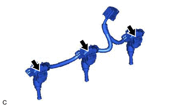
(b) for Bank 1:
(1) Connect the 3 fuel injector assembly connectors.
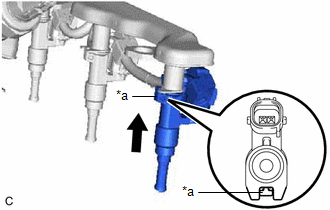
| (2) Install the 3 fuel injector assemblies to the fuel delivery pipe with sensor assembly. NOTICE:
|
|
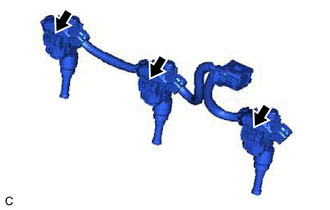
(3) Engage the clamp to connect the No. 5 engine wire to the fuel delivery pipe with sensor assembly.
(c) for Bank 2:
(1) Connect the 3 fuel injector assembly connectors.
| (2) Install the 3 fuel injector assemblies to the fuel delivery pipe with sensor assembly. NOTICE:
|
|
(3) Engage the clamp to connect the No. 5 engine wire to the fuel delivery pipe with sensor assembly.
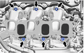
2. INSTALL INJECTOR VIBRATION INSULATOR
(a) Install 6 new injector vibration insulators to the intake manifold.
3. INSTALL NO. 1 DELIVERY PIPE SPACER
(a) Install the 4 No. 1 delivery pipe spacers to the intake manifold.
4. INSTALL FUEL DELIVERY PIPE WITH SENSOR ASSEMBLY
(a) Place the fuel delivery pipe with sensor assembly with the 6 fuel injector assemblies onto the intake manifold.
NOTICE:
Be careful not to drop the fuel injector assemblies when installing the fuel delivery pipe with sensor assembly.
(b) Install the fuel delivery pipe with sensor assembly with the 6 fuel injector assemblies to the intake manifold with the 4 bolts.
Torque:
17 N·m {173 kgf·cm, 13 ft·lbf}
(c) Connect the 2 No. 5 engine wire connectors.
(d) Connect the fuel pressure sensor connector.
5. CONNECT FUEL TUBE SUB-ASSEMBLY
(a) Connect the fuel tube sub-assembly to the fuel delivery pipe with sensor assembly.
Click here
6. INSTALL INTAKE AIR SURGE TANK ASSEMBLY
Click here
7. CONNECT CABLE TO NEGATIVE BATTERY TERMINAL
Click here
8. INSPECT FOR FUEL LEAK
Click here
9. PERFORM INITIALIZATION
(a) Perform "Inspection After Repair" after replacing a fuel injector assembly.
Click here
REMOVAL
CAUTION / NOTICE / HINT
The necessary procedures (adjustment, calibration, initialization or registration) that must be performed after parts are removed and installed, or replaced during fuel injector assembly removal/installation are shown below.
Necessary Procedures After Parts Removed/Installed/Replaced|
Replaced Part or Performed Procedure |
Necessary Procedure | Effect/Inoperative Function when Necessary Procedure not Performed |
Link |
|---|---|---|---|
|
*: When performing learning using the Techstream.
Click here | |||
|
Battery terminal is disconnected/reconnected |
Perform steering sensor zero point calibration |
Lane Departure Alert System (w/ Steering Control) |
|
|
Pre-collision System | |||
|
Intelligent Clearance Sonar System* | |||
|
Lighting System (for Gasoline Model with Cornering Light) | |||
|
Memorize steering angle neutral point |
Parking Assist Monitor System |
| |
|
Panoramic View Monitor System |
| ||
| Inspection after repair |
|
|
CAUTION:
PROCEDURE
1. PRECAUTION
NOTICE:
After turning the engine switch off, waiting time may be required before disconnecting the cable from the negative (-) battery terminal. Therefore, make sure to read the disconnecting the cable from the negative (-) battery terminal notices before proceeding with work.
Click here

2. DISCHARGE FUEL SYSTEM PRESSURE
Click here
3. DISCONNECT CABLE FROM NEGATIVE BATTERY TERMINAL
Click here
4. REMOVE INTAKE AIR SURGE TANK ASSEMBLY
Click here
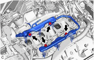
5. DISCONNECT FUEL TUBE SUB-ASSEMBLY
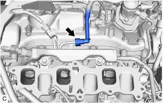
| (a) Disconnect the fuel tube sub-assembly from the fuel delivery pipe with sensor assembly. Click here |
|
6. REMOVE FUEL DELIVERY PIPE WITH SENSOR ASSEMBLY
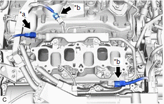
| (a) Disconnect the fuel pressure sensor connector. |
|
(b) Disconnect the 2 No. 5 engine wire connectors.
| (c) Remove the 4 bolts and fuel delivery pipe with sensor assembly with the 6 fuel injector assemblies from the intake manifold. NOTICE:
|
|
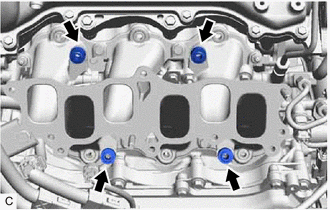
7. REMOVE NO. 1 DELIVERY PIPE SPACER
| (a) Remove the 4 No. 1 delivery pipe spacers from the intake manifold. |
|
8. REMOVE INJECTOR VIBRATION INSULATOR
| (a) Remove the 6 injector vibration insulators from the intake manifold. |
|
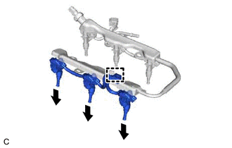
9. REMOVE FUEL INJECTOR ASSEMBLY
(a) for Bank 2:
| (1) Disengage the clamp to disconnect the No. 5 engine wire from the fuel delivery pipe with sensor assembly. |
|
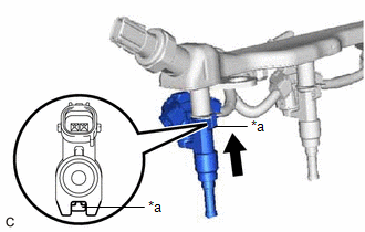
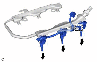
(2) Pull the 3 fuel injector assemblies out of the fuel delivery pipe with sensor assembly.
| (3) Disconnect the 3 fuel injector assembly connectors. |
|
(b) for Bank 1:
| (1) Disengage the clamp to disconnect the No. 5 engine wire from the fuel delivery pipe with sensor assembly. |
|
(2) Pull the 3 fuel injector assemblies out of the fuel delivery pipe with sensor assembly.
| (3) Disconnect the 3 fuel injector assembly connectors. |
|
(c) Remove the O-ring from each fuel injector assembly.
| (d) Attach a tag or label with the corresponding cylinder number to each fuel injector assembly so that they can be installed to their original locations. NOTICE: Cover the fuel injector assemblies with plastic bags to prevent damage and contamination. |
|
Toyota Avalon (XX50) 2019-2022 Service & Repair Manual > Door / Hatch: Hood
Adjustment ADJUSTMENT CAUTION / NOTICE / HINT *a Centering Bolt *b Standard Bolt HINT: Centering bolts are used to install the hood hinges and hood lock. The hood and hood lock cannot be adjusted with the centering bolts installed. Substitute the centering bolts with standard bolts with washers when ...