COMPONENTS
ILLUSTRATION
|
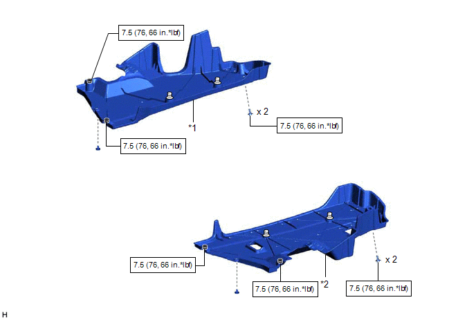
*1 | NO. 1 FLOOR UNDER COVER |
*2 | NO. 2 FLOOR UNDER COVER |
 |
N*m (kgf*cm, ft.*lbf): Specified torque |
- | - |
ILLUSTRATION
|
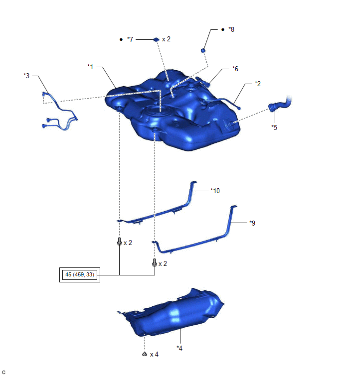
*1 | FUEL TANK ASSEMBLY |
*2 | FUEL TANK BREATHER TUBE SUB-ASSEMBLY |
|
*3 | FUEL TANK MAIN TUBE SUB-ASSEMBLY |
*4 | NO. 1 FUEL TANK PROTECTOR |
|
*5 | FUEL TANK TO FILLER PIPE HOSE |
*6 | FUEL TANK VENT HOSE SUB-ASSEMBLY |
|
*7 | NO. 1 FUEL TANK CUSHION |
*8 | NO. 6 FUEL TANK CUSHION |
|
*9 | NO. 1 FUEL TANK BAND SUB-ASSEMBLY LH |
*10 | NO. 1 FUEL TANK BAND SUB-ASSEMBLY RH |
 |
Tightening torque for "Major areas involving basic vehicle performance such as moving/turning/stopping": N*m (kgf*cm, ft.*lbf) |
● | Non-reusable part |
INSTALLATION
PROCEDURE
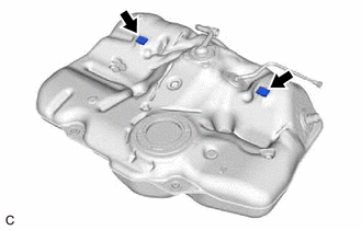
1. INSTALL NO. 1 FUEL TANK CUSHION
(a) Install 2 new No. 1 fuel tank cushions to the fuel tank assembly.
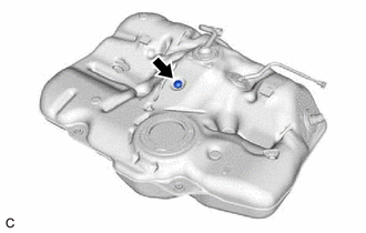
2. INSTALL NO. 6 FUEL TANK CUSHION
(a) Install a new No. 6 fuel tank cushion to the fuel tank assembly.
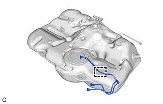
3. INSTALL FUEL TANK MAIN TUBE SUB-ASSEMBLY
(a) Engage the clamp to install the fuel tank main tube sub-assembly to the fuel tank assembly.
4. INSTALL FUEL TANK ASSEMBLY
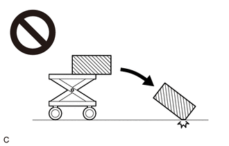
CAUTION:
The fuel tank assembly is very heavy. Be sure to follow the procedure described in the repair manual, or the fuel tank assembly may fall off the engine lifter.
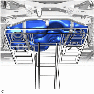
(a) Set the fuel tank assembly on an engine lifter.
NOTICE:
Using height adjustment attachments and plate lift attachments, keep the fuel tank assembly horizontal.
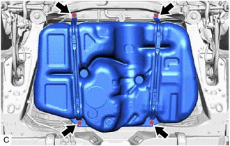
| (b) Using the engine lifter, slowly raise the fuel tank assembly, and then install the fuel tank assembly, No. 1 fuel tank band sub-assembly LH and No. 1 fuel tank band sub-assembly RH with the 4 bolts in the order shown in the illustration. Torque: 45 N·m {459 kgf·cm, 33 ft·lbf} NOTICE:
|
|
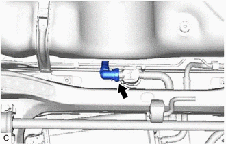
(c) Connect the fuel tank vent hose sub-assembly to the fuel outlet valve assembly.
Click here 
5. CONNECT FUEL TANK TO FILLER PIPE HOSE
(a) Connect the fuel tank to filler pipe hose to the fuel tank assembly.
Click here
6. CONNECT FUEL TANK BREATHER TUBE SUB-ASSEMBLY
(a) Connect the fuel tank breather tube sub-assembly to the fuel pipe.
Click here
7. CONNECT FUEL TANK MAIN TUBE SUB-ASSEMBLY
(a) Connect the fuel tank main tube sub-assembly to the fuel pipe.
Click here
8. INSTALL NO. 1 FUEL TANK PROTECTOR
(a) Install the No. 1 fuel tank protector to the fuel tank assembly with the 4 clips.
9. INSTALL NO. 1 FLOOR UNDER COVER
Click here
10. INSTALL NO. 2 FLOOR UNDER COVER
Click here
11. INSTALL CENTER EXHAUST PIPE ASSEMBLY
Click here
12. INSTALL FUEL SUCTION TUBE WITH PUMP AND GAUGE ASSEMBLY
Click here
13. ADD FUEL
REMOVAL
CAUTION / NOTICE / HINT
The necessary procedures (adjustment, calibration, initialization or registration) that must be performed after parts are removed and installed, or replaced during fuel tank assembly removal/installation are shown below.
Necessary Procedures After Parts Removed/Installed/Replaced|
Replaced Part or Performed Procedure |
Necessary Procedure | Effect/Inoperative Function when Necessary Procedure not Performed |
Link |
|---|---|---|---|
|
*: When performing learning using the Techstream.
Click here | |||
|
Battery terminal is disconnected/reconnected |
Perform steering sensor zero point calibration |
Lane Departure Alert System (w/ Steering Control) |
|
|
Pre-collision System | |||
|
Intelligent Clearance Sonar System* | |||
|
Lighting System (for Gasoline Model with Cornering Light) | |||
|
Memorize steering angle neutral point |
Parking Assist Monitor System |
| |
|
Panoramic View Monitor System |
| ||
|
Gas leak from exhaust system is repaired |
Inspection after repair |
|
|
CAUTION:

PROCEDURE
1. REMOVE FUEL SUCTION TUBE WITH PUMP AND GAUGE ASSEMBLY
Click here 
2. DRAIN FUEL
3. REMOVE CENTER EXHAUST PIPE ASSEMBLY
Click here
4. REMOVE NO. 2 FLOOR UNDER COVER
Click here
5. REMOVE NO. 1 FLOOR UNDER COVER
Click here
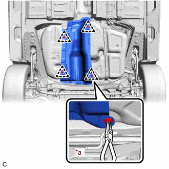
6. REMOVE NO. 1 FUEL TANK PROTECTOR
| (a) Using needle nose pliers, remove the 4 clips and No. 1 fuel tank protector from the fuel tank assembly. |
|
7. DISCONNECT FUEL TANK MAIN TUBE SUB-ASSEMBLY
| (a) Disconnect the fuel tank main tube sub-assembly from the fuel pipe. Click here |
|
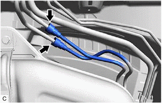
8. DISCONNECT FUEL TANK BREATHER TUBE SUB-ASSEMBLY
| (a) Disconnect the fuel tank breather tube sub-assembly from the fuel pipe. Click here |
|
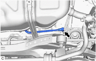
9. DISCONNECT FUEL TANK TO FILLER PIPE HOSE
| (a) Disconnect the fuel tank to filler pipe hose from the fuel tank assembly. Click here |
|
10. REMOVE FUEL TANK ASSEMBLY
CAUTION:
The fuel tank assembly is very heavy. Be sure to follow the procedure described in the repair manual, or the fuel tank assembly may fall off the engine lifter.
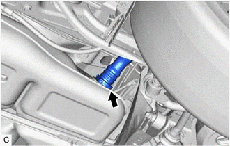
| (a) Disconnect the fuel tank vent hose sub-assembly from the fuel outlet valve assembly. Click here |
|
| (b) Support the fuel tank assembly using an engine lifter. HINT: Using height adjustment attachments and plate lift attachments, keep the fuel tank assembly horizontal. |
|
| (c) Remove the 4 bolts, No. 1 fuel tank band sub-assembly LH and No. 1 fuel tank band sub-assembly RH. |
|
(d) Lower the engine lifter to remove the fuel tank assembly.
NOTICE:
11. REMOVE FUEL TANK MAIN TUBE SUB-ASSEMBLY
| (a) Disengage the clamp to remove the fuel tank main tube sub-assembly from the fuel tank assembly. |
|
12. REMOVE NO. 6 FUEL TANK CUSHION
| (a) Remove the No. 6 fuel tank cushion from the fuel tank assembly. |
|
13. REMOVE NO. 1 FUEL TANK CUSHION
| (a) Remove the 2 No. 1 fuel tank cushions from the fuel tank assembly. |
|
Toyota Avalon (XX50) 2019-2022 Owners Manual > Opening, closing and
locking the doors: Doors
Unlocking and locking the doors from the outside Smart key system Carry the electronic key to enable this function. Grip the driver's door handle to unlock the door. Holding the driver's door handle for approximately 2 seconds unlocks all the doors. Grip the front passenger's door handle to unlock a ...