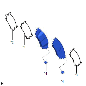
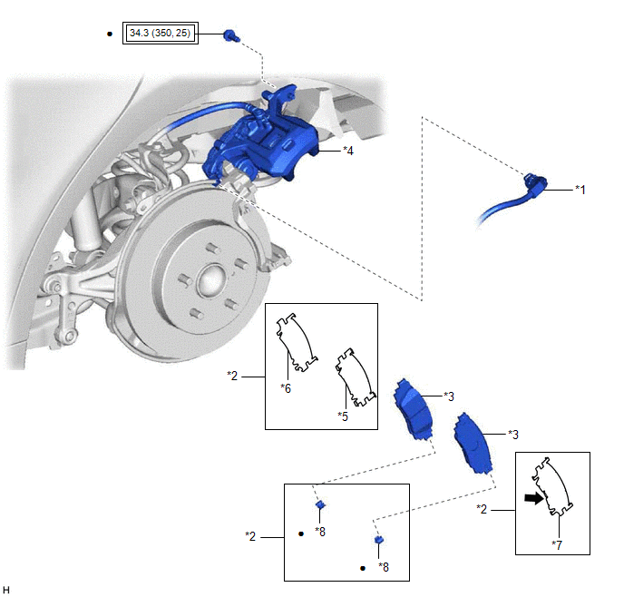
COMPONENTS
ILLUSTRATION
|
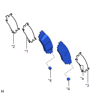
*1 | NO. 2 PARKING BRAKE WIRE ASSEMBLY |
*2 | REAR DISC BRAKE ANTI-SQUEAL SHIM KIT |
|
*3 | REAR DISC BRAKE PAD |
*4 | REAR DISC BRAKE CYLINDER ASSEMBLY |
|
*5 | REAR NO. 1 DISC BRAKE ANTI-SQUEAL SHIM |
*6 | REAR NO. 2 DISC BRAKE ANTI-SQUEAL SHIM |
|
*7 | REAR DISC BRAKE ANTI-SQUEAL SHIM |
*8 | REAR DISC BRAKE PAD WEAR INDICATOR PLATE |
 |
Tightening torque for "Major areas involving basic vehicle performance such as moving/turning/stopping": N*m (kgf*cm, ft.*lbf) |
● | Non-reusable part |
 |
Disc brake grease | - |
- |
INSTALLATION
CAUTION / NOTICE / HINT
NOTICE:
HINT:
PROCEDURE
1. INSTALL REAR DISC BRAKE ANTI-SQUEAL SHIM KIT
NOTICE:
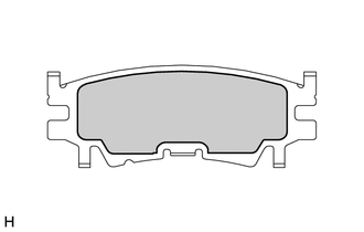
| (a) Check the rear disc brake pad. HINT: If the rear disc brake pad has an identification mark, be sure to confirm the installation location. |
|
(b) Apply disc brake grease to the inner side of the rear disc brake anti-squeal shim as shown in the illustration.
 |
Disc Brake Grease |
| (c) Install the rear No. 1 disc brake anti-squeal shim to the rear disc brake pad (inside). |
|
(d) Install the rear No. 2 disc brake anti-squeal shim to the rear disc brake pad (inside).
(e) Install the rear disc brake anti-squeal shim to the rear disc brake pad (outside).
NOTICE:
Install the rear disc brake anti-squeal shim so that its claws are toward the outside of the vehicle.
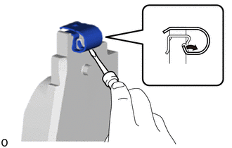
(f) Install a new rear disc brake pad wear indicator plate to each rear disc brake pad.
2. INSTALL REAR DISC BRAKE PAD
CAUTION:
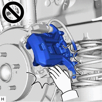
(a) Push in the rear disc brake piston.
NOTICE:
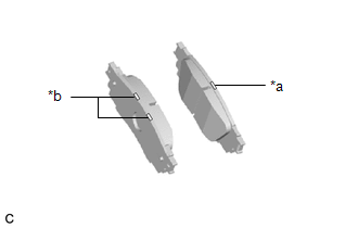
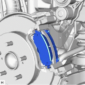
(b) Install the 2 rear disc brake pads to the rear disc brake cylinder mounting.
NOTICE:
HINT:
If the rear disc brake pad has an identification mark, be sure to confirm the installation location.

|
*a | Inner Side (White) |
|
*b | Outer Side (White) |
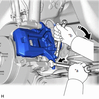
(c) Hold the rear No. 1 disc brake cylinder slide pin and install the rear disc brake cylinder assembly to the rear disc brake cylinder mounting with a new bolt.
Torque:
34.3 N·m {350 kgf·cm, 25 ft·lbf}
(d) Depress the brake pedal several times. (for Gasoline Model)
3. CONNECT NO. 2 PARKING BRAKE WIRE ASSEMBLY
Click here

4. CONNECT CABLE TO NEGATIVE AUXILIARY BATTERY TERMINAL (for HV Model)
(a) Connect the reservoir level switch connector.
(b) Connect the cable to the negative (-) auxiliary battery terminal.
Click here
(c) Turn the power switch on (READY).
(d) Depress the brake pedal and release it.
(e) Clear the DTCs.
Click here
5. INSPECT BRAKE FLUID LEVEL IN RESERVOIR
for Gasoline Model: Click here
for HV Model: Click here
6. INSTALL REAR WHEEL
Click here
7. NORMAL CONDITION RECOVERY
for Gasoline Model: Click here
for HV Model: Click here
REMOVAL
CAUTION / NOTICE / HINT
The necessary procedures (adjustment, calibration, initialization, or registration) that must be performed after parts are removed and installed, or replaced during rear disc brake pad removal/installation are shown below.
Necessary Procedures After Parts Removed/Installed/Replaced|
Replaced Part or Performed Procedure |
Necessary Procedure | Effect/Inoperative Function when Necessary Procedure not Performed |
Link |
|---|---|---|---|
|
*1: for HV Model
*2: When performing learning using the Techstream. Click here
| |||
|
Auxiliary battery terminal is disconnected/reconnected*1 |
Perform steering sensor zero point calibration |
Lane Departure Alert System (w/ Steering Control) |
|
|
Pre-collision System | |||
|
Intelligent Clearance Sonar System*2 | |||
|
Lighting System (for HV Model with Cornering Light) | |||
|
Memorize steering angle neutral point |
Parking Assist Monitor System |
| |
|
Panoramic View Monitor System |
| ||
NOTICE:
HINT:
PROCEDURE
1. PRECAUTION (for HV Model)
NOTICE:
Click here 
Click here
2. REMOVE REAR WHEEL
Click here
3. PERFORM REAR BRAKE PAD REPLACEMENT MODE
for Gasoline Model: Click here
for HV Model: Click here
4. DISABLE BRAKE CONTROL (for HV Model)
Click here
5. DISCONNECT NO. 2 PARKING BRAKE WIRE ASSEMBLY
Click here
6. REMOVE REAR DISC BRAKE PAD
CAUTION:

| (a) Hold the rear No. 1 disc brake cylinder slide pin and remove the bolt. |
|
(b) Pull the rear disc brake cylinder assembly upward.
| (c) Remove the 2 rear disc brake pads from the rear disc brake cylinder mounting. |
|
7. REMOVE REAR DISC BRAKE ANTI-SQUEAL SHIM KIT
| (a) Remove the rear No. 2 disc brake anti-squeal shim from the rear disc brake pad (inside). |
|
(b) Remove the rear No. 1 disc brake anti-squeal shim from the rear disc brake pad (inside).
(c) Remove the rear disc brake anti-squeal shim from the rear disc brake pad (outside).
| (d) Remove the rear disc brake pad wear indicator plate from each rear disc brake pad. |
|
Toyota Avalon (XX50) 2019-2022 Service & Repair Manual > Sfi System: System Too Lean Bank 1 (P017100,P017200,P017400,P017500,P117000,P117B00)
DESCRIPTION The fuel trim is related to the feedback compensation value, not to the basic injection duration. The fuel trim consists of both the short-term and long-term fuel trims. The short-term fuel trim is fuel compensation that is used to constantly maintain the air fuel ratio at stoichiometric ...