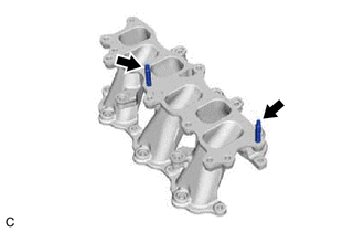
INSTALLATION PROCEDURE 1. INSTALL STUD BOLT HINT: If a stud bolt is deformed or the threads are damaged, replace it.
2. INSTALL NO. 1 INTAKE MANIFOLD TO HEAD GASKET (a) Install 2 new No. 1 intake manifold to head gaskets to each cylinder head sub-assembly. NOTICE:
3. INSTALL INTAKE MANIFOLD (a) Temporarily install the intake manifold to the cylinder head sub-assembly with the 4 bolts and 4 nuts. (b) Tighten the 4 bolts and 4 nuts in the order shown in the illustration. 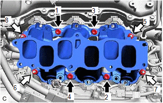
Torque: 21 N·m {214 kgf·cm, 15 ft·lbf} 4. INSTALL INJECTOR VIBRATION INSULATOR Click here
5. INSTALL NO. 1 DELIVERY PIPE SPACER Click here 6. INSTALL FUEL DELIVERY PIPE WITH SENSOR ASSEMBLY Click here 7. CONNECT FUEL TUBE SUB-ASSEMBLY Click here 8. INSTALL NO. 2 ENGINE MOUNTING STAY RH
(b) Install the No. 2 engine mounting stay RH to the engine mounting insulator sub-assembly RH with the bolt and 2 nuts. 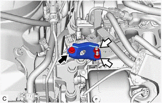
Torque: 20 N·m {204 kgf·cm, 15 ft·lbf} (c) Connect the wire harness clamp bracket to the No. 2 engine mounting stay RH with the bolt. Torque: 10 N·m {102 kgf·cm, 7 ft·lbf} (d) Connect the wire harness clamp to the wire harness clamp bracket with the bolt. Torque: 10 N·m {102 kgf·cm, 7 ft·lbf} 9. INSTALL NO. 1 V-BANK COVER BRACKET HINT: Perform this procedure only when replacement of the No. 1 V-bank cover bracket is necessary. (a) Install the 2 No. 1 V-bank cover brackets to the intake air surge tank assembly. Torque: 9.0 N·m {92 kgf·cm, 80 in·lbf} 10. INSTALL AIR SURGE TANK TO INTAKE MANIFOLD GASKET (a) Install a new air surge tank to intake manifold gasket to the intake air surge tank assembly. 11. INSTALL INTAKE AIR SURGE TANK ASSEMBLY NOTICE: Do not apply oil to the bolts and nuts as listed below:
(a) Install the plug to the intake air surge tank assembly. (b) Temporarily install the intake air surge tank assembly to the intake manifold with the 5 bolts and 2 nuts. (c) Temporarily install the No. 2 surge tank stay to the intake air surge tank assembly and camshaft housing RH with the 2 bolts. (d) Tighten the 5 bolts and 2 nuts in the order shown in the illustration. Torque: 21 N·m {214 kgf·cm, 15 ft·lbf} 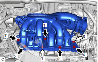
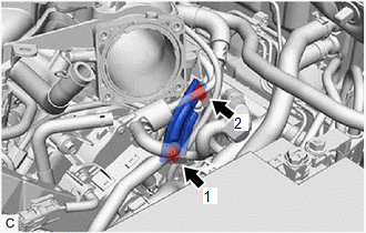
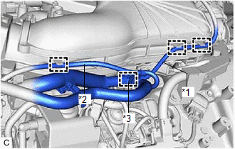
(g) Engage the clamp to connect the vacuum hose to the intake air surge tank assembly. (h) Engage the 2 clamps to connect the vacuum hose sub-assembly to the intake air surge tank assembly.
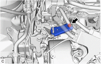
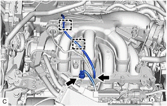
(j) Connect the vacuum switching valve (for ACIS) connector. 12. CONNECT PURGE VALVE (PURGE VSV) (a) Connect the purge valve (purge VSV) to the intake air surge tank assembly with the bolt. Torque: 21 N·m {214 kgf·cm, 15 ft·lbf} (b) Connect the No. 1 fuel vapor feed hose to the intake air surge tank assembly. 13. CONNECT VENTILATION HOSE (a) Connect the ventilation hose to the intake air surge tank assembly and slide the clip to secure it. 14. INSTALL THROTTLE BODY WITH MOTOR ASSEMBLY Click here
15. INSTALL FRONT CENTER UPPER SUSPENSION BRACE SUB-ASSEMBLY Click here 16. INSTALL COWL TOP VENTILATOR LOUVER SUB-ASSEMBLY Click here 17. CONNECT CABLE TO NEGATIVE BATTERY TERMINAL NOTICE: When disconnecting the cable, some systems need to be initialized after the cable is reconnected. Click here 18. INSPECT FOR FUEL LEAK Click here 19. INSTALL V-BANK COVER SUB-ASSEMBLY Click here |
Toyota Avalon (XX50) 2019-2022 Service & Repair Manual > Navigation System(for Gasoline Model): Satellite Radio Broadcast cannot be Received
CAUTION / NOTICE / HINT NOTICE: Some satellite radio broadcasts require payment. A contract must be made between a satellite radio company and the user. If the contract expires, it will not be possible to listen to the broadcast. PROCEDURE 1. CHECK SURROUNDINGS (a) Check if the vehicle is in an envi ...