DESCRIPTION
Refer to DTC P26CA12.
Click here

|
DTC No. | Detection Item |
DTC Detection Condition | Trouble Area |
MIL | Memory |
Note |
|---|---|---|---|---|---|---|
| P26CA14 |
Engine Coolant Pump Circuit Short to Ground or Open |
The operation duty ratio (WPO) of the monitoring water inlet housing with water pump sub-assembly becomes a certain amount or less when water inlet housing with water pump sub-assembly operation command is output (1 trip detection logic). |
| Comes on |
DTC stored | SAE Code: P26CC |
|
DTC No. | Data List |
|---|---|
|
P26CA14 |
|
MONITOR DESCRIPTION
The ECM outputs an operation duty signal (WPO) to steplessly control the speed of the water inlet housing with water pump sub-assembly. The ECM outputs an operation duty signal (WPO) to the water inlet housing with water pump sub-assembly and monitors the actual duty signal (WPO) being output. When the operation duty signal (WPO) is being output to the to the water inlet housing with water pump sub-assembly and the actual operation duty signal (WPO) is a certain value or less, the ECM detects a malfunction and stores a DTC.
MONITOR STRATEGY
|
Related DTCs | P26CC: Engine water pump circuit range check (Low voltage) |
|
Required Sensors/Components (Main) | Water inlet housing with water pump sub-assembly |
|
Required Sensors/Components (Related) |
- |
| Frequency of Operation |
Continuous |
| Duration |
3 seconds |
| MIL Operation |
Immediate |
| Sequence of Operation |
None |
TYPICAL ENABLING CONDITIONS
|
All of the following conditions are met |
- |
| Auxiliary battery voltage |
8 V or higher |
|
Power switch | On (IG) |
|
Time after power switch off to on (IG) |
0.5 seconds or more |
|
Output duty cycle | 30 to 85% |
|
Engine water pump circuit pulse input fail (P26CA) |
Not detected |
TYPICAL MALFUNCTION THRESHOLDS
|
Both of the following conditions are met |
- |
| Water inlet housing with water pump sub-assembly output terminal voltage level |
Low |
| Water inlet housing with water pump sub-assembly output signal |
No signal |
CONFIRMATION DRIVING PATTERN
HINT:
Click here
Click here
Click here
HINT:
|
Techstream Display |
Description |
|---|---|
|
NORMAL |
|
|
ABNORMAL |
|
|
INCOMPLETE |
|
HINT:
The normal judgment procedure is used to complete DTC judgment and also used when clearing permanent DTCs.
WIRING DIAGRAM
Refer to DTC P26CA12.
Click here
CAUTION / NOTICE / HINT
NOTICE:
Click here
(Select Powertrain in Health Check and then check the time stamp data.)
Click here
Click here
HINT:
Read Freeze Frame Data using the Techstream. The ECM records vehicle and driving condition information as Freeze Frame Data the moment a DTC is stored. When troubleshooting, Freeze Frame Data can help determine if the vehicle was moving or stationary, if the engine was warmed up or not, if the air fuel ratio was lean or rich, and other data from the time the malfunction occurred.
PROCEDURE
| 1. |
INSPECT ECM (INTERNAL CIRCUIT) |
|
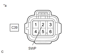
*a | Front view of wire harness connector (to Water Inlet Housing with Water Pump Sub-assembly) |
(a) Disconnect the water inlet housing with water pump sub-assembly connector.
(b) Turn the power switch on (IG).
(c) Measure the resistance according to the value(s) in the table below.
Standard:
|
Tester Connection | Condition |
Specified Condition |
|---|---|---|
|
C39-2 (SWP) - Body ground |
Power switch on (IG) |
Resistance fluctuates* |
HINT:
| NG |  | REPLACE ECM |
|
| 2. |
CHECK HARNESS AND CONNECTOR (WATER INLET HOUSING WITH WATER PUMP SUB-ASSEMBLY - ECM) |
(a) Disconnect the water inlet housing with water pump sub-assembly connector.
(b) Disconnect the ECM connector.
(c) Measure the resistance according to the value(s) in the table below.
Standard Resistance:
|
Tester Connection | Condition |
Specified Condition |
|---|---|---|
|
C39-2 (SWP) - C55-50 (WPO) |
Always | Below 1 Ω |
|
C39-2 (SWP) or C55-50 (WPO) - Body ground |
Always | 10 kΩ or higher |
| OK | | REPLACE WATER INLET HOUSING WITH WATER PUMP SUB-ASSEMBLY |
| NG | | REPAIR OR REPLACE HARNESS OR CONNECTOR |
DESCRIPTION
Refer to DTC P26CA12.
Click here

|
DTC No. | Detection Item |
DTC Detection Condition | Trouble Area |
MIL | Memory |
Note |
|---|---|---|---|---|---|---|
| P26CA31 |
Engine Coolant Pump No Signal |
The speed of the water inlet housing with water pump sub-assembly calculated from the WPI signal is less than 10 rpm (open or short in the WPI circuit) (1 trip detection logic). |
| Comes on |
DTC stored | SAE Code: P26CA |
|
DTC No. | Data List |
|---|---|
|
P26CA31 |
|
MONITOR DESCRIPTION
The ECM receives a frequency signal (WPI) from the water inlet housing with water pump sub-assembly and calculates the speed of the water inlet housing with water pump sub-assembly. As the frequency signal (WPI) is 4 Hz when the water inlet housing with water pump sub-assembly is stopped to enable the ECM to detect an open or short in the signal line, the water inlet housing with water pump sub-assembly speed will be displayed as approximately 160 rpm even when the pump is stopped. If the water inlet housing with water pump sub-assembly speed is calculated to be less than 10 rpm, the ECM judges that there is an open or short in the WPI circuit and stores this DTC.
MONITOR STRATEGY
|
Related DTCs | P26CA: Engine water pump circuit verify pulse input |
|
Required Sensors/Components (Main) | Water inlet housing with water pump sub-assembly |
|
Required Sensors/Components (Related) |
- |
| Frequency of Operation |
Continuous |
| Duration |
15 seconds |
| MIL Operation |
Immediate |
| Sequence of Operation |
None |
TYPICAL ENABLING CONDITIONS
|
Monitor runs whenever the following DTCs are not stored |
None |
| All of the following conditions are met |
- |
| Auxiliary battery voltage |
8 V or higher |
|
Power switch | On (IG) |
|
Time after power switch off to on (IG) |
0.5 seconds or more |
TYPICAL MALFUNCTION THRESHOLDS
|
Engine water pump speed | Less than 10 rpm |
CONFIRMATION DRIVING PATTERN
HINT:
Click here
Click here
Click here
HINT:
|
Techstream Display |
Description |
|---|---|
|
NORMAL |
|
|
ABNORMAL |
|
|
INCOMPLETE |
|
HINT:
The normal judgment procedure is used to complete DTC judgment and also used when clearing permanent DTCs.
WIRING DIAGRAM
Refer to DTC P26CA12.
Click here
CAUTION / NOTICE / HINT
NOTICE:
Click here
(Select Powertrain in Health Check and then check the time stamp data.)
Click here
Click here
HINT:
Read Freeze Frame Data using the Techstream. The ECM records vehicle and driving condition information as Freeze Frame Data the moment a DTC is stored. When troubleshooting, Freeze Frame Data can help determine if the vehicle was moving or stationary, if the engine was warmed up or not, if the air fuel ratio was lean or rich, and other data from the time the malfunction occurred.
PROCEDURE
| 1. |
CHECK TERMINAL VOLTAGE (POWER SOURCE OF WATER INLET HOUSING WITH WATER PUMP SUB-ASSEMBLY) |
|
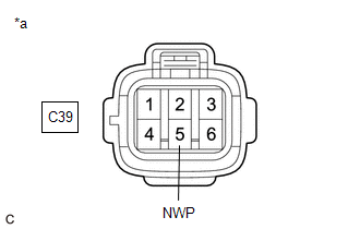
*a | Front view of wire harness connector (to Water Inlet Housing with Water Pump Sub-assembly) |
(a) Disconnect the water inlet housing with water pump sub-assembly connector.
(b) Turn the power switch on (IG).
(c) Measure the voltage according to the value(s) in the table below.
Standard Voltage:
|
Tester Connection | Condition |
Specified Condition |
|---|---|---|
|
C39-5 (NWP) - Body ground |
Power switch on (IG) |
11 to 14 V |
| NG |  | GO TO STEP 8 |
|
| 2. |
CHECK HARNESS AND CONNECTOR (WATER INLET HOUSING WITH WATER PUMP SUB-ASSEMBLY - BODY GROUND) |
(a) Disconnect the water inlet housing with water pump sub-assembly connector.
(b) Measure the resistance according to the value(s) in the table below.
Standard Resistance:
|
Tester Connection | Condition |
Specified Condition |
|---|---|---|
|
C39-3 (PGN2) - Body ground |
Always | Below 1 Ω |
|
C39-6 (PGND) - Body ground |
Always | Below 1 Ω |
| NG | | REPAIR OR REPLACE HARNESS OR CONNECTOR |
|
| 3. |
CHECK TERMINAL VOLTAGE (POWER SOURCE OF WATER INLET HOUSING WITH WATER PUMP SUB-ASSEMBLY) |
|
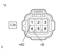
*a | Front view of wire harness connector (to Water Inlet Housing with Water Pump Sub-assembly) |
(a) Disconnect the water inlet housing with water pump sub-assembly connector.
(b) Turn the power switch on (IG).
(c) Measure the voltage according to the value(s) in the table below.
Standard Voltage:
|
Tester Connection | Condition |
Specified Condition |
|---|---|---|
|
C39-1 (+B2) - Body ground |
Power switch on (IG) |
11 to 14 V |
|
C39-4 (+B) - Body ground |
Power switch on (IG) |
11 to 14 V |
| OK | | REPLACE WATER INLET HOUSING WITH WATER PUMP SUB-ASSEMBLY |
|
| 4. |
INSPECT EFI-MAIN NO. 3 RELAY |
(a) Inspect the EFI-MAIN NO. 3 relay.
Click here
| NG | | REPLACE EFI-MAIN NO. 3 RELAY |
|
| 5. |
CHECK HARNESS AND CONNECTOR (POWER SOURCE OF EFI-MAIN NO. 3 RELAY) |
|
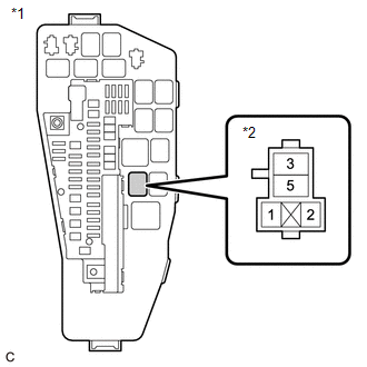
*1 | No. 1 Engine Room Relay Block and No. 1 Junction Block Assembly |
|
*2 | EFI-MAIN NO. 3 Relay |
(a) Remove the EFI-MAIN NO. 3 relay from the No. 1 engine room relay block and No. 1 junction block assembly.
(b) Measure the voltage according to the value(s) in the table below.
Standard Voltage:
|
Tester Connection | Condition |
Specified Condition |
|---|---|---|
|
3 (EFI-MAIN NO. 3 relay) - Body ground |
Always | 11 to 14 V |
| NG | | REPAIR OR REPLACE HARNESS OR CONNECTOR (AUXILIARY BATTERY - EFI-MAIN NO. 3 RELAY) |
|
| 6. |
CHECK HARNESS AND CONNECTOR (EFI-MAIN NO. 3 RELAY - BODY GROUND) |
(a) Remove the EFI-MAIN NO. 3 relay from the No. 1 engine room relay block and No. 1 junction block assembly.
(b) Measure the resistance according to the value(s) in the table below.
Standard Resistance:
|
Tester Connection | Condition |
Specified Condition |
|---|---|---|
|
1 (EFI-MAIN NO. 3 relay) - Body ground |
Always | Below 1 Ω |
| NG | | REPAIR OR REPLACE HARNESS OR CONNECTOR |
|
| 7. |
CHECK HARNESS AND CONNECTOR (EFI-MAIN NO. 3 RELAY - WATER INLET HOUSING WITH WATER PUMP SUB-ASSEMBLY) |
(a) Remove the EFI-MAIN NO. 3 relay from the No. 1 engine room relay block and No. 1 junction block assembly.
(b) Disconnect the water inlet housing with water pump sub-assembly connector.
(c) Measure the resistance according to the value(s) in the table below.
Standard Resistance:
|
Tester Connection | Condition |
Specified Condition |
|---|---|---|
|
5 (EFI-MAIN NO. 3 relay) - C39-1 (+B2) |
Always | Below 1 Ω |
|
5 (EFI-MAIN NO. 3 relay) - C39-4 (+B) |
Always | Below 1 Ω |
|
5 (EFI-MAIN NO. 3 relay), C39-1 (+B2) or C39-4 (+B) - Body ground and other terminals |
Always | 10 kΩ or higher |
| OK | | REPAIR OR REPLACE HARNESS OR CONNECTOR (EFI-MAIN NO. 1 RELAY - EFI-MAIN NO. 3 RELAY) |
| NG | | REPAIR OR REPLACE HARNESS OR CONNECTOR |
| 8. |
CHECK HARNESS AND CONNECTOR (WATER INLET HOUSING WITH WATER PUMP SUB-ASSEMBLY - ECM) |
(a) Disconnect the water inlet housing with water pump sub-assembly connector.
(b) Disconnect the ECM connector.
(c) Measure the resistance according to the value(s) in the table below.
Standard Resistance:
|
Tester Connection | Condition |
Specified Condition |
|---|---|---|
|
C39-5 (NWP) - C55-51 (WPI) |
Always | Below 1 Ω |
|
C39-5 (NWP) or C55-51 (WPI) - Body ground and other terminals |
Always | 10 kΩ or higher |
| OK | | REPLACE ECM |
| NG | | REPAIR OR REPLACE HARNESS OR CONNECTOR |
DESCRIPTION
Refer to DTC P26CA12.
Click here

|
DTC No. | Detection Item |
DTC Detection Condition | Trouble Area |
MIL | Memory |
Note |
|---|---|---|---|---|---|---|
| P26CB71 |
Engine Coolant Pump Actuator Stuck |
Even though an operation request signal is being output, the water inlet housing with water pump sub-assembly does not rotate* (1 trip detection logic). |
| Comes on |
DTC stored | SAE Code: P26CB |
*: As the frequency signal (WPI) is 4 Hz when the water inlet housing with water pump sub-assembly is stopped to enable the ECM to detect an open or short in the signal line, the water inlet housing with water pump sub-assembly speed will be displayed as approximately 160 rpm even when the pump is stopped. If there is an open in the WPI circuit, the water inlet housing with water pump sub-assembly speed will be displayed as 0 rpm.
Related Data List|
DTC No. | Data List |
|---|---|
|
P26CB71 |
|
MONITOR DESCRIPTION
The ECM receives a frequency signal (WPI) from the water inlet housing with water pump sub-assembly and calculates the speed of the water inlet housing with water pump sub-assembly. The ECM outputs an operation duty signal (WPO) to steplessly control the speed of the water inlet housing with water pump sub-assembly. If the duty signal (WPI) indicates that the water inlet housing with water pump sub-assembly is stopped even though the ECM is outputting an operation duty signal (WPO), the ECM judges that the water inlet housing with water pump sub-assembly is stuck and stores this DTC.
As the frequency signal (WPI) is 4 Hz when the water inlet housing with water pump sub-assembly is stopped to enable the ECM to detect an open or short in the signal line, the water inlet housing with water pump sub-assembly speed will be displayed as approximately 160 rpm even when the pump is stopped.
MONITOR STRATEGY
|
Related DTCs | P26CB: Engine water pump motor lock |
|
Required Sensors/Components (Main) | Water inlet housing with water pump sub-assembly |
|
Required Sensors/Components (Related) |
- |
| Frequency of Operation |
Continuous |
| Duration |
Less than 30 seconds |
| MIL Operation |
Immediate |
| Sequence of Operation |
None |
TYPICAL ENABLING CONDITIONS
|
All of the following conditions are met |
- |
| Engine coolant temperature |
-10°C (-50°F) or higher |
|
Engine water pump output duty ratio |
30 to 85% |
| Auxiliary battery voltage |
Higher than 8 V |
|
Engine coolant temperature sensor malfunction (P0117, P0118) |
Not detected |
|
Engine water pump (IN) malfunction (P26CA) |
Not detected |
|
Engine water pump (OUT) malfunction (P26CC, P26CD) |
Not detected |
TYPICAL MALFUNCTION THRESHOLDS
|
Fail Counter* | 15 seconds or more |
|
*: Count up fail counter when both of the following conditions are met |
(a) and (b) |
|
(a) Engine water pump (IN) motor speed |
100 rpm or higher |
| (b) Engine water pump (IN) motor speed |
Less than 170 rpm |
CONFIRMATION DRIVING PATTERN
HINT:
Click here
Click here
Click here
HINT:
|
Techstream Display |
Description |
|---|---|
|
NORMAL |
|
|
ABNORMAL |
|
|
INCOMPLETE |
|
HINT:
The normal judgment procedure is used to complete DTC judgment and also used when clearing permanent DTCs.
WIRING DIAGRAM
Refer to DTC P26CA12.
Click here
CAUTION / NOTICE / HINT
NOTICE:
Click here
(Select Powertrain in Health Check and then check the time stamp data.)
Click here
Click here
HINT:
PROCEDURE
|
1. | CHECK ANY OTHER DTCS OUTPUT (IN ADDITION TO DTC P26CB71) |
(a) Connect the Techstream to the DLC3.
(b) Turn the power switch on (IG).
(c) Turn the Techstream on.
(d) Enter the following menus: Powertrain / Engine / Trouble Codes.
(e) Read the DTCs.
Powertrain > Engine > Trouble Codes|
Result | Proceed to |
|---|---|
|
DTC P26CB71 is output |
A |
| DTC P26CB71 and P26CE37 are output | |
|
DTC P26CB71 and other DTCs are output |
B |
HINT:
If any DTCs other than P26CB71 are output, troubleshoot those DTCs first.
| B |
 | GO TO DTC CHART |
|
| 2. |
CHECK ENGINE COOLANT LEVEL IN RESERVOIR TANK |
(a) Check that the engine coolant level is between the FULL and LOW lines.
Click here
|
Result | Proceed to |
|---|---|
|
Engine coolant level is above the LOW line |
A |
| Engine coolant level is below the LOW line |
B |
| A |
| GO TO STEP 6 |
|
| 3. |
CHECK FOR ENGINE COOLANT LEAKS |
(a) Check the areas around the engine and heater for engine coolant leaks.
Click here
HINT:
If the engine oil is cloudy during the engine oil level gauge check, it means that engine coolant has entered the engine lubrication system.
OK:
No leaks.
| NG | | GO TO STEP 5 |
|
| 4. |
ADD ENGINE COOLANT |
(a) Fill the reservoir tank up to the FULL line with engine coolant.
NOTICE:
Make sure not to add engine coolant when the engine is hot.
| NEXT | | GO TO STEP 6 |
| 5. |
REPAIR OR REPLACE MALFUNCTIONING PARTS, COMPONENT AND AREA |
(a) Repair any engine coolant leaks.
HINT:
Add engine coolant and perform air bleeding after repair.
|
| 6. |
PERFORM ACTIVE TEST USING TECHSTREAM (ACTIVATE THE ELECTRIC WATER PUMP) |
(a) Connect the Techstream to the DLC3.
(b) Turn the power switch on (IG).
(c) Turn the Techstream on.
(d) Enter the following menus: Powertrain / Engine / Active Test / Activate the Electric Water Pump / Data List / Electric Water Pump Speed.
Powertrain > Engine > Active Test|
Active Test Display |
|---|
|
Activate the Electric Water Pump |
|
Data List Display |
|---|
|
Electric Water Pump Speed |
(e) According to the display on the Techstream, read the Data List while performing the Active Test.
Standard:
|
Active Test Operation | Electric Water Pump Speed |
|---|---|
|
3000 rpm | 2000 rpm or higher |
| OK | | GO TO STEP 8 |
|
| 7. |
INSPECT ECM (INTERNAL CIRCUIT) |

|
*a | Front view of wire harness connector (to Water Inlet Housing with Water Pump Sub-assembly) |
(a) Disconnect the water inlet housing with water pump sub-assembly connector.
(b) Turn the power switch on (IG).
(c) Measure the resistance according to the value(s) in the table below.
Standard:
|
Tester Connection | Condition |
Specified Condition |
|---|---|---|
|
C39-2 (SWP) - Body ground |
Power switch on (IG) |
Resistance fluctuates* |
HINT:
| NG | | REPLACE ECM |
|
| 8. |
REPLACE WATER INLET HOUSING WITH WATER PUMP SUB-ASSEMBLY |
(a) Replace the water inlet housing with water pump sub-assembly.
Click here
HINT:
When replacing any cooling system parts, if excessive deposits of rust or scale exist or the concentration of the engine coolant is abnormal, replace the engine coolant.
|
| 9. |
CLEAR DTC |
(a) Connect the Techstream to the DLC3.
(b) Turn the power switch on (IG).
(c) Turn the Techstream on.
(d) Clear the DTCs.
Powertrain > Engine > Clear DTCs(e) Turn the power switch off and wait for at least 30 seconds.
|
| 10. |
CHECK WHETHER DTC OUTPUT RECURS (DTC P26CB71) |
(a) Drive the vehicle in accordance with the driving pattern described in Confirmation Driving Pattern.
(b) Enter the following menus: Powertrain / Engine / Trouble Codes.
(c) Read the DTCs.
Powertrain > Engine > Trouble CodesHINT:
If no DTC is output, the repair has been successfully completed.
| NEXT | | END |
Toyota Avalon (XX50) 2019-2022 Service & Repair Manual > Alignment / Handling Diagnosis: Rear Wheel Alignment
Adjustment ADJUSTMENT CAUTION / NOTICE / HINT The necessary procedures (adjustment, calibration, initialization, or registration) that must be performed after completing the rear wheel alignment procedure are shown below. Necessary Procedures After Procedure Performed Replaced Part or Performed Proc ...


