DESCRIPTION Refer to DTC P019011. Click here
 |
DTC No. | Detection Item |
DTC Detection Condition | Trouble Area |
MIL | Memory |
Note | | P01902A |
Fuel Rail Pressure Sensor "A" Signal Stuck in Range |
When
target high pressure side fuel pressure changes, the change in fuel
pressure sensor value is abnormal (2 trip detection logic). |
- Fuel pressure
- Fuel pressure sensor (for high pressure side)
- Open or short in fuel pressure sensor (for high pressure side) circuit
- ECM
| Comes on |
DTC stored | SAE Code: P0191 | |
P019064 | Fuel Rail Pressure Sensor "A" Signal Plausibility Failure |
Although
engine has been stopped and left as is for a long time, high pressure
side fuel pressure is higher or lower than threshold (2 trip detection
logic). |
- Fuel pressure
- Fuel pressure sensor (for high pressure side)
- Open or short in fuel pressure sensor (for high pressure side) circuit
- ECM
| Comes on |
DTC stored | SAE Code: P0191 | MONITOR DESCRIPTION Fuel Pressure Sensor Stuck Monitor
If
the fuel pressure sensor (for high pressure side) value does not follow
the change in the target high pressure side fuel pressure, it is judged
as a malfunction. If this malfunction is detected in 2 consecutive
driving cycles, the ECM will illuminate the MIL and store DTC P01902A. Fuel Pressure Sensor Correlation Monitor with Barometric Pressure
If
the fuel pressure sensor (for high pressure side) value is less than or
higher than the threshold value when a cold start is performed after
the engine has been warmed up and then stopped, it is judged as a
malfunction has occurred. If this malfunction is detected for 2
consecutive driving cycles, the ECM will illuminate the MIL and store
DTC P019064. MONITOR STRATEGY |
Related DTCs | P0191: Fuel pressure sensor rationality (stuck monitor)
P0191: Fuel pressure sensor rationality (correlation monitor with barometric pressure) | |
Required Sensors/Components (Main) | Fuel pressure sensor (for high pressure side) | |
Required Sensors/Components (Related) |
Atmospheric pressure sensor (ECM) | |
Frequency of Operation | Continuous | |
Duration | Within 30 seconds: Stuck monitor
Within 10 seconds: Correlation monitor with barometric pressure | |
MIL Operation | 2 driving cycles | |
Sequence of Operation | None | TYPICAL ENABLING CONDITIONS Stuck Monitor |
All of the following conditions are met |
- | | Fuel pressure sensor (for high pressure side) circuit malfunction (P0192, P0193) |
Not detected | |
High pressure fuel pump malfunction (P1235) |
Not detected | | Engine coolant temperature sensor malfunction (P0117, P0118) |
Not detected | | Barometric pressure sensor malfunction (P106C, P2228, P2229) |
Not detected | | Auxiliary battery voltage |
11 V or higher | | Fuel cut |
Off | | Injection mode |
NOT PFI (Port fuel injection) | Correlation Monitor with Barometric Pressure |
All of the following conditions are met |
- | | Fuel pressure sensor (for high pressure side) circuit malfunction (P0192, P0193) |
Not detected | |
High pressure fuel pump malfunction (P1235) |
Not detected | | Engine coolant temperature sensor malfunction (P0117, P0118) |
Not detected | | Barometric pressure sensor malfunction (P106C, P2228, P2229) |
Not detected | |
Soak timer malfunction (P2610) |
Not detected | | Auxiliary battery voltage |
8 V or higher | | Power switch |
Off | | Soak time |
5, 7 or 9.5 hours | | Atmospheric pressure |
76 kPa(abs) [11 psi(abs)] or higher | TYPICAL MALFUNCTION THRESHOLDS Stuck Monitor |
Malfunction counter | 5 times or more | |
Fuel pressure sensor (for high pressure side) output deviation |
Less than 0.3 MPa (3.1 kgf/cm2, 43.5 psi) | Correlation Monitor with Barometric Pressure |
Malfunction counter | 5 seconds or more | |
Fuel pressure sensor (for high pressure side) output |
Less than -1.15 MPa (-11.7 kgf/cm2, -167 psi), or higher than 1.769 MPa (18 kgf/cm2, 257 psi) | CONFIRMATION DRIVING PATTERN
HINT:
- After repair has been completed, clear the DTC and then check that the
vehicle has returned to normal by performing the following All Readiness
check procedure.
Click here
- When clearing the permanent DTCs, refer to the "CLEAR PERMANENT DTC" procedure.
Click here
- Connect the Techstream to the DLC3.
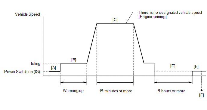
- Turn the power switch on (IG).
- Turn the Techstream on.
- Clear the DTCs (even if no DTCs are stored, perform the clear DTC procedure).
- Turn the power switch off and wait for at least 30 seconds.
- Turn the power switch on (IG) [A].
- Turn the Techstream on.
- Put the engine in Inspection Mode (Maintenance Mode).
Click here
- Start the engine and warm it up until the engine coolant temperature reaches 75°C (167°F) or higher [B].
- With the engine running, drive the vehicle for 15 minutes or more [C].
CAUTION:
When performing the confirmation driving pattern, obey all speed limits and traffic laws.
HINT:
If the engine stops, further depress the accelerator pedal to restart the engine.
- Turn the power switch off.
- With the engine stopped, leave the vehicle as is for 5 hours or more [D].
- Turn the power switch on (IG) [E].
- Turn the Techstream on.
- Enter the following menus: Powertrain / Engine / Trouble Codes [F].
- Read the pending DTCs.
HINT:
- If a pending DTC is output, the system is malfunctioning.
- If a pending DTC is not output, perform the following procedure.
- Enter the following menus: Powertrain / Engine / Utility / All Readiness.
- Input the DTC: P01902A or P019064.
- Check the DTC judgment result.
|
Techstream Display |
Description |
|
NORMAL |
- DTC judgment completed
- System normal
|
|
ABNORMAL |
- DTC judgment completed
- System abnormal
|
|
INCOMPLETE |
- DTC judgment not completed
- Perform driving pattern after confirming DTC enabling conditions
|
HINT:
WIRING DIAGRAM Refer to DTC P019011. Click here
CAUTION / NOTICE / HINT
NOTICE:
HINT: Read
Freeze Frame Data using the Techstream. The ECM records vehicle and
driving condition information as Freeze Frame Data the moment a DTC is
stored. When troubleshooting, Freeze Frame Data can help determine if
the vehicle was moving or stationary, if the engine was warmed up or
not, if the air fuel ratio was lean or rich, and other data from the
time the malfunction occurred. PROCEDURE
| 1. |
CHECK ANY OTHER DTCS OUTPUT (IN ADDITION TO DTC P01902A OR P019064) |
(a) Connect the Techstream to the DLC3. (b) Turn the power switch on (IG).
(c) Turn the Techstream on. (d) Enter the following menus: Powertrain / Engine / Trouble Codes.
(e) Read the DTCs. Powertrain > Engine > Trouble Codes
|
Result | Proceed to | |
DTC P01902A or P019064 is output |
A | | DTC P01902A or P019064 and P008700, P008800, P017100 or P017200 are output | |
DTC P01902A or P019064 and other DTCs are output |
B |
HINT:
- If DTC P01902A or P019064 and P008700, P008800, P017100 or P017200 are
output simultaneously, troubleshoot for DTC P01902A or P019064 first.
- If any DTCs other than P01902A or P019064 are output, troubleshoot those DTCs first.
| B |
 | GO TO DTC CHART |
|
A |
 | |
(a) Check around and beneath the vehicle for fuel leaks, fumes, etc.
OK: No fuel leaks present.
| NG |
| GO TO STEP 11 |
|
OK | |
| |
| 3. |
PERFORM ACTIVE TEST USING TECHSTREAM (CONTROL THE TARGET FUEL PRESSURE OFFSET) |
(a) Connect the Techstream to the DLC3. (b) Turn the power switch on (IG).
(c) Turn the Techstream on. (d) Put the engine in Inspection Mode (Maintenance Mode). Powertrain > Hybrid Control > Utility
|
Tester Display | | Inspection Mode |
(e) Start the engine and warm it up until the engine coolant temperature reaches 75°C (167°F) or higher.
(f)
Enter the following menus: Powertrain / Engine / Active Test / Control
the Target Fuel Pressure Offset / Data List / Coolant Temperature and
High Fuel Pressure Sensor. Powertrain > Engine > Active Test
|
Active Test Display | |
Control the Target Fuel Pressure Offset |
|
Data List Display | |
Coolant Temperature | |
High Fuel Pressure Sensor | (g)
Check the value of the Data List item "High Fuel Pressure Sensor" when
the target fuel pressure is increased and decreased using the Active
Test. |
Result | Proceed to | |
"High Fuel Pressure Sensor" value follows the change in target fuel pressure |
A | | "High Fuel Pressure Sensor" value does not follow the change in target fuel pressure |
B |
| B |
| GO TO STEP 10 |
|
A | |
| |
| 4. |
CHECK HARNESS AND CONNECTOR (FUEL PRESSURE SENSOR (FOR HIGH PRESSURE SIDE) - ECM) |
(a) Disconnect the fuel pressure sensor (for high pressure side) connector.
(b) Disconnect the ECM connector. (c) Measure the resistance according to the value(s) in the table below.
Standard Resistance: |
Tester Connection | Condition |
Specified Condition | |
U1-3 (PR) - C55-97 (PR) |
Always | Below 1 Ω | |
U1-2 (E2) - C55-96 (EPR) |
Always | Below 1 Ω | |
U1-3 (PR) or C55-97 (PR) - Body ground and other terminals |
Always | 10 kΩ or higher |
| NG |
| GO TO STEP 8 |
|
OK | |
| |
| 5. |
REPLACE FUEL PRESSURE SENSOR (FOR HIGH PRESSURE SIDE) |
(a) Replace the fuel pressure sensor (for high pressure side). Click here
HINT: Perform "Inspection After Repair" after replacing the fuel pressure sensor (for high pressure side).
Click here
|
NEXT | |
| |
(a) Connect the Techstream to the DLC3.
(b) Turn the power switch on (IG). (c) Turn the Techstream on. (d) Clear the DTCs. Powertrain > Engine > Clear DTCs
(e) Turn the power switch off and wait for at least 30 seconds.
|
NEXT | |
| |
| 7. |
CHECK WHETHER DTC OUTPUT RECURS (DTC P01902A OR P019064) |
(a) Drive the vehicle in accordance with the driving pattern described in Confirmation Driving Pattern.
(b) Enter the following menus: Powertrain / Engine / Trouble Codes. (c) Read the pending DTCs. Powertrain > Engine > Trouble Codes
|
Result | Proceed to | |
DTCs are not output | A | |
DTC P01902A or P019064 is output |
B |
| A |
| END |
| B |
| GO TO STEP 9 |
| 8. |
REPAIR OR REPLACE HARNESS OR CONNECTOR |
(a) Repair or replace the wire harness or connector.
| NEXT |
| GO TO STEP 12 |
(a) Replace the ECM.
Click here
| NEXT |
| GO TO STEP 12 |
| 10. |
REPLACE FUEL PRESSURE SENSOR (FOR HIGH PRESSURE SIDE) |
(a) Replace the fuel pressure sensor (for high pressure side). Click here
HINT: Perform "Inspection After Repair" after replacing the fuel pressure sensor (for high pressure side).
Click here
| NEXT |
| GO TO STEP 12 |
| 11. |
REPAIR OR REPLACE FUEL LEAK POINT | (a) Repair or replace the fuel leak point.
|
NEXT | |
| |
(a) Connect the Techstream to the DLC3.
(b) Turn the power switch on (IG). (c) Turn the Techstream on. (d) Clear the DTCs. Powertrain > Engine > Clear DTCs
(e) Turn the power switch off and wait for at least 30 seconds.
|
NEXT | |
| |
| 13. |
CHECK WHETHER DTC OUTPUT RECURS (DTC P01902A OR P019064) |
(a) Drive the vehicle in accordance with the driving pattern described in Confirmation Driving Pattern.
(b) Enter the following menus: Powertrain / Engine / Trouble Codes. (c) Read the pending DTCs. Powertrain > Engine > Trouble Codes
OK: DTCs are not output.
| NEXT | |
END | | 

