DESCRIPTION
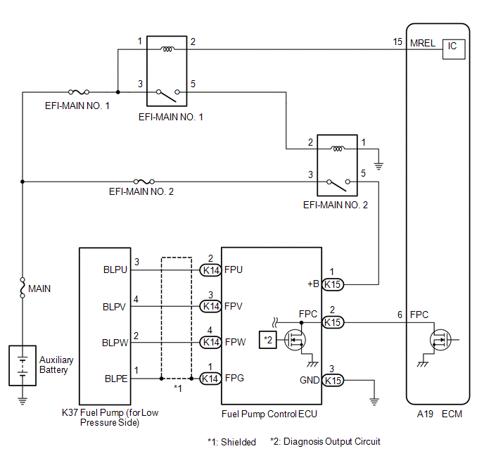
The fuel pump control ECU performs PWM (Pulse Width Modulation) control to control the fuel pump (for low pressure side) speed steplessly over a wide range.
The fuel pump control ECU controls the speed of the fuel pump (for low pressure side) by switching the current of FPU, FPV and FPW based on operation signals output from the ECM.
|
DTC No. | Detection Item |
DTC Detection Condition | Trouble Area |
MIL | Memory |
Note |
|---|---|---|---|---|---|---|
| P062712 |
Fuel Pump "A" Control Circuit Short to Battery |
When the fuel pump control ECU operation duty ratio is 3 to 65%, the FPC terminal voltage is at a certain value or more for 3 seconds or more (1 trip detection logic). |
| Comes on |
DTC stored | SAE Code: P0629 |
|
DTC No. | Data List |
|---|---|
|
P062712 | Fuel Pump Control Duty Ratio |
MONITOR DESCRIPTION
The ECM monitors the fuel pump control ECU operation signals.
When the output duty ratio of the operation signal from the ECM is 3 to 65% and the FPC terminal voltage is a certain value or more for 3 seconds or more, the ECM stores a DTC.
MONITOR STRATEGY
|
Related DTCs | P0629: Fuel pump control circuit range check (high voltage) |
|
Required Sensors/Components (Main) | Fuel pump control ECU |
|
Required Sensors/Components (Related) |
- |
| Frequency of Operation |
Continuous |
| Duration |
3 seconds |
| MIL Operation |
Immediate |
| Sequence of Operation |
None |
TYPICAL ENABLING CONDITIONS
|
Monitor runs whenever the following DTCs are not stored |
None |
| All of the following conditions are met |
- |
| Output duty cycle |
3 to 65% |
| Auxiliary battery voltage |
10.5 V or higher |
| Power switch |
On (IG) |
TYPICAL MALFUNCTION THRESHOLDS
|
Fuel pump control module terminal voltage level |
High for 0.3 seconds or more |
CONFIRMATION DRIVING PATTERN
HINT:
Click here 
Click here
Click here
HINT:
|
Techstream Display |
Description |
|---|---|
|
NORMAL |
|
|
ABNORMAL |
|
|
INCOMPLETE |
|
HINT:
The normal judgment procedure is used to complete DTC judgment and also used when clearing permanent DTCs.
WIRING DIAGRAM
CAUTION / NOTICE / HINT
NOTICE:
Click here
(Select Powertrain in Health Check and then check the time stamp data.)
Click here
Click here
HINT:
Read Freeze Frame Data using the Techstream. The ECM records vehicle and driving condition information as Freeze Frame Data the moment a DTC is stored. When troubleshooting, Freeze Frame Data can help determine if the vehicle was moving or stationary, if the engine was warmed up or not, if the air fuel ratio was lean or rich, and other data from the time the malfunction occurred.
PROCEDURE
| 1. |
INSPECT ECM (CHECK FOR SHORT) |
|
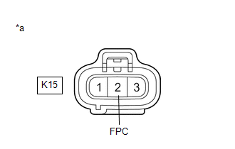
*a | Front view of wire harness connector (to Fuel Pump Control ECU) |
(a) Disconnect the fuel pump control ECU connector.
(b) Turn the power switch on (IG).
(c) Measure the voltage according to the value(s) in the table below.
Standard Voltage:
|
Tester Connection | Condition |
Specified Condition |
|---|---|---|
|
K15-2 (FPC) - Body ground |
Power switch on (IG) |
Below 1 V |
| OK |  | REPLACE FUEL PUMP CONTROL ECU |
|
| 2. |
CHECK HARNESS AND CONNECTOR (FUEL PUMP CONTROL ECU - ECM) |
(a) Disconnect the fuel pump control ECU connector.
(b) Disconnect the ECM connector.
(c) Measure the resistance according to the value(s) in the table below.
Standard Resistance:
|
Tester Connection | Condition |
Specified Condition |
|---|---|---|
|
K15-2 (FPC) or A19-6 (FPC) - Other terminals |
Always | 10 kΩ or higher |
| OK | | REPLACE ECM |
| NG | | REPAIR OR REPLACE HARNESS OR CONNECTOR |
DESCRIPTION
Refer to DTC P062712.
Click here

|
DTC No. | Detection Item |
DTC Detection Condition | Trouble Area |
MIL | Memory |
Note |
|---|---|---|---|---|---|---|
| P062714 |
Fuel Pump "A" Control Circuit Short to Ground or Open |
When the fuel pump control ECU operation duty ratio is 3 to 65%, the FPC terminal voltage is a certain value or less for 3 seconds or more (1 trip detection logic). |
| Comes on |
DTC stored | SAE Code: P0628 |
|
DTC No. | Data List |
|---|---|
|
P062714 | Fuel Pump Control Duty Ratio |
MONITOR DESCRIPTION
The ECM monitors the fuel pump control ECU operation signals.
When the output duty ratio of the operation signal from the ECM is 3 to 65% and the FPC terminal voltage is a certain value or less for 3 seconds or more, the ECM stores a DTC.
MONITOR STRATEGY
|
Related DTCs | P0628: Fuel pump control circuit range check (low voltage) |
|
Required Sensors/Components (Main) | Fuel pump control ECU |
|
Required Sensors/Components (Related) |
- |
| Frequency of Operation |
Continuous |
| Duration |
3 seconds |
| MIL Operation |
Immediate |
| Sequence of Operation |
None |
TYPICAL ENABLING CONDITIONS
|
Monitor runs whenever the following DTCs are not stored |
None |
| All of the following conditions are met |
- |
| Output duty cycle |
3 to 65% |
| Auxiliary battery voltage |
10.5 V or higher |
| Power switch |
On (IG) |
TYPICAL MALFUNCTION THRESHOLDS
|
Fuel pump control module terminal voltage level |
Low for 1.163264 seconds or more |
CONFIRMATION DRIVING PATTERN
HINT:
Click here
Click here
Click here
HINT:
|
Techstream Display |
Description |
|---|---|
|
NORMAL |
|
|
ABNORMAL |
|
|
INCOMPLETE |
|
HINT:
The normal judgment procedure is used to complete DTC judgment and also used when clearing permanent DTCs.
WIRING DIAGRAM
Refer to DTC P062712.
Click here
CAUTION / NOTICE / HINT
NOTICE:
Click here
(Select Powertrain in Health Check and then check the time stamp data.)
Click here
Click here
HINT:
Read Freeze Frame Data using the Techstream. The ECM records vehicle and driving condition information as Freeze Frame Data the moment a DTC is stored. When troubleshooting, Freeze Frame Data can help determine if the vehicle was moving or stationary, if the engine was warmed up or not, if the air fuel ratio was lean or rich, and other data from the time the malfunction occurred.
PROCEDURE
| 1. |
CHECK HARNESS AND CONNECTOR (POWER SOURCE OF FUEL PUMP CONTROL ECU) |
|
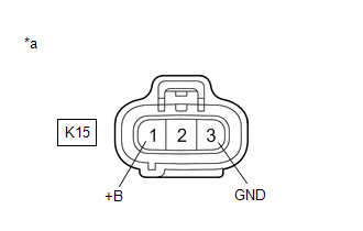
*a | Front view of wire harness connector (to Fuel Pump Control ECU) |
(a) Disconnect the fuel pump control ECU connector.
(b) Turn the power switch on (IG).
(c) Measure the voltage according to the value(s) in the table below.
Standard Voltage:
|
Tester Connection | Condition |
Specified Condition |
|---|---|---|
|
K15-1 (+B) - K15-3 (GND) |
Power switch on (IG) |
11 to 14 V |
| NG |  | GO TO STEP 4 |
|
| 2. |
INSPECT ECM (FPC TERMINAL) |

|
*a | Front view of wire harness connector (to Fuel Pump Control ECU) |
(a) Disconnect the fuel pump control ECU connector.
(b) Connect the Techstream to the DLC3.
(c) Turn the power switch on (IG).
(d) Turn the Techstream on.
(e) Enter the following menus: Powertrain / Engine / Active Test / Fuel Pump Single Phase Energization.
Powertrain > Engine > Active Test|
Tester Display |
|---|
| Fuel Pump Single Phase Energization |
(f) Operate the fuel pump control ECU using the Active Test function and measure the resistance according to the value(s) in the table below.
Standard Resistance:
|
Tester Connection | Techstream Operation |
Specified Condition |
|---|---|---|
|
K15-2 (FPC) - Body ground |
Before Active Test → During Active Test |
Before Active Test: Resistance is stable → During Active Test: Resistance fluctuates* |
HINT:
*: Using the Active Test, duty control of the transistors in the ECM will be performed. Due to the duty control, resistance of the FPC terminal will be unstable during the Active Test. If the resistance is stable before the Active Test and fluctuates while performing the Active Test, it can be determined that the transistor is operating. If the transistor does not operate during the Active Test, the ECM may be malfunctioning.
| OK | | REPLACE FUEL PUMP CONTROL ECU |
|
| 3. |
CHECK HARNESS AND CONNECTOR (FUEL PUMP CONTROL ECU - ECM) |
(a) Disconnect the fuel pump control ECU connector.
(b) Disconnect the ECM connector.
(c) Measure the resistance according to the value(s) in the table below.
Standard Resistance:
|
Tester Connection | Condition |
Specified Condition |
|---|---|---|
|
K15-2 (FPC) - A19-6 (FPC) |
Always | Below 1 Ω |
|
K15-2 (FPC) or A19-6 (FPC) - Body ground |
Always | 10 kΩ or higher |
| OK | | REPLACE ECM |
| NG | | REPAIR OR REPLACE HARNESS OR CONNECTOR |
| 4. |
CHECK HARNESS AND CONNECTOR (FUEL PUMP CONTROL ECU - BODY GROUND) |
(a) Disconnect the fuel pump control ECU connector.
(b) Measure the resistance according to the value(s) in the table below.
Standard Resistance:
|
Tester Connection | Condition |
Specified Condition |
|---|---|---|
|
K15-3 (GND) - Body ground |
Always | Below 1 Ω |
| NG | | REPAIR OR REPLACE HARNESS OR CONNECTOR |
|
| 5. |
INSPECT EFI-MAIN NO. 2 RELAY |
(a) Inspect the EFI-MAIN NO. 2 relay.
Click here
| NG | | REPLACE EFI-MAIN NO. 2 RELAY |
|
| 6. |
CHECK TERMINAL VOLTAGE (POWER SOURCE OF EFI-MAIN NO. 2 RELAY) |
|
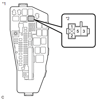
*1 | No. 1 Engine Room Relay Block and No. 1 Junction Block Assembly |
|
*2 | EFI-MAIN NO. 2 Relay |
(a) Remove the EFI-MAIN NO. 2 relay from the No. 1 engine room relay block and No. 1 junction block assembly.
(b) Measure the voltage according to the value(s) in the table below.
Standard Voltage:
|
Tester Connection | Condition |
Specified Condition |
|---|---|---|
|
3 (EFI-MAIN NO. 2 relay) - Body ground |
Always | 11 to 14 V |
| NG | | REPAIR OR REPLACE HARNESS OR CONNECTOR (AUXILIARY BATTERY - EFI-MAIN NO. 2 RELAY) |
|
| 7. |
CHECK HARNESS AND CONNECTOR (EFI-MAIN NO. 2 RELAY - BODY GROUND) |
(a) Remove the EFI-MAIN NO. 2 relay from the No. 1 engine room relay block and No. 1 junction block assembly.
(b) Measure the resistance according to the value(s) in the table below.
Standard Resistance:
|
Tester Connection | Condition |
Specified Condition |
|---|---|---|
|
1 (EFI-MAIN NO. 2 relay) - Body ground |
Always | Below 1 Ω |
| NG | | REPAIR OR REPLACE HARNESS OR CONNECTOR |
|
| 8. |
CHECK HARNESS AND CONNECTOR (FUEL PUMP CONTROL ECU - EFI-MAIN NO. 2 RELAY) |
(a) Disconnect the fuel pump control ECU connector.
(b) Remove the EFI-MAIN NO. 2 relay from the No. 1 engine room relay block and No. 1 junction block assembly.
(c) Measure the resistance according to the value(s) in the table below.
Standard Resistance:
|
Tester Connection | Condition |
Specified Condition |
|---|---|---|
|
K15-1 (+B) - 5 (EFI-MAIN NO. 2 relay) |
Always | Below 1 Ω |
|
K15-1 (+B) or 5 (EFI-MAIN NO. 2 relay) - Body ground and other terminals |
Always | 10 kΩ or higher |
| OK | | REPAIR OR REPLACE HARNESS OR CONNECTOR (EFI-MAIN NO. 1 RELAY - EFI-MAIN NO. 2 RELAY) |
| NG | | REPAIR OR REPLACE HARNESS OR CONNECTOR |
MONITOR DESCRIPTION
DTC P063051 is stored when the Vehicle Identification Number (VIN) is not stored in the ECM or the stored VIN is not accurate.
|
DTC No. | Detection Item |
DTC Detection Condition | Trouble Area |
MIL | Memory |
Note |
|---|---|---|---|---|---|---|
| P063051 |
VIN Not Programmed | Either of the following conditions is met (1 trip detection logic):
|
| Comes on |
DTC stored | SAE Code: P0630 |
MONITOR STRATEGY
|
Related DTCs | P0630: VIN not programmed |
|
Required Sensors/Components (Main) | ECM |
|
Required Sensors/Components (Related) | - |
|
Frequency of Operation | Continuous |
|
Duration | - |
| MIL Operation |
Immediate |
| Sequence of Operation |
None |
TYPICAL ENABLING CONDITIONS
|
Monitor runs whenever the following DTCs are not stored |
None |
| All of the following conditions are met |
- |
| Reading VIN | No error |
|
Auxiliary battery voltage | 8 V or higher |
|
Power switch | On (IG) |
TYPICAL MALFUNCTION THRESHOLDS
|
VIN | Not programmed |
CONFIRMATION DRIVING PATTERN
HINT:
Click here 
Click here
HINT:
|
Techstream Display |
Description |
|---|---|
|
NORMAL |
|
|
ABNORMAL |
|
|
INCOMPLETE |
|
HINT:
The normal judgment procedure is used to complete DTC judgment and also used when clearing permanent DTCs.
CAUTION / NOTICE / HINT
NOTICE:
Click here
(Select Powertrain in Health Check and then check the time stamp data.)
Click here
Click here
HINT:
Read Freeze Frame Data using the Techstream. The ECM records vehicle and driving condition information as Freeze Frame Data the moment a DTC is stored. When troubleshooting, Freeze Frame Data can help determine if the vehicle was moving or stationary, if the engine was warmed up or not, if the air fuel ratio was lean or rich, and other data from the time the malfunction occurred.
PROCEDURE
| 1. |
CHECK ANY OTHER DTCS OUTPUT (IN ADDITION TO DTC P063051) |
(a) Connect the Techstream to the DLC3.
(b) Turn the power switch on (IG).
(c) Turn the Techstream on.
(d) Enter the following menus: Powertrain / Engine / Trouble Codes.
(e) Read the DTCs.
Powertrain > Engine > Trouble CodesNOTICE:
If P063051 is output, the VIN must be written to the ECM using the Techstream. However, all DTCs are cleared automatically by the Techstream when the VIN is written. If DTCs other than P063051 are output, troubleshoot them first.
|
Result | Proceed to |
|---|---|
|
DTC P063051 is output |
A |
| DTC P063051 and other DTCs are output |
B |
| B |
 | GO TO DTC CHART |
|
| 2. |
WRITE VIN |
(a) Write the VIN.
Click here
| NEXT | |
END |
Toyota Avalon (XX50) 2019-2022 Service & Repair Manual > Sfi System: ECM/PCM Engine Off Timer Performance Signal Invalid (P261029,P261093). Parts Location. Precaution
ECM/PCM Engine Off Timer Performance Signal Invalid (P261029,P261093) DTC SUMMARY DTC No. Detection Item DTC Detection Condition Trouble Area MIL Memory Note P261029 ECM/PCM Engine Off Timer Performance Signal Invalid ECM internal malfunction ECM Comes on DTC stored SAE Code: P2610 P261093 ECM/PCM E ...


