DESCRIPTION
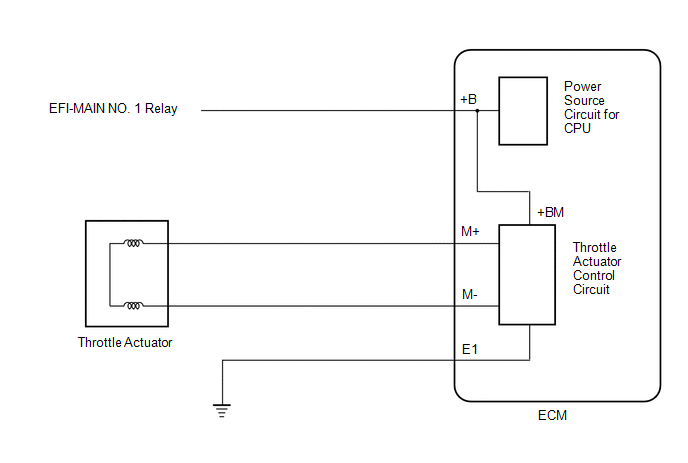
The electronic throttle control system has a dedicated power supply circuit. The voltage (+BM) is monitored and when it is low (less than 4 V), the ECM determines that there is a malfunction in the electronic throttle control system and cuts off the current to the throttle actuator.
When the voltage becomes unstable, the electronic throttle control system itself becomes unstable. For this reason, when the voltage is low, the current to the throttle actuator is cut. If repairs are made and the system returns to normal, turn the power switch off. If a malfunction is not detected the ECM allows current to flow to the throttle actuator so that it can operate.
|
DTC No. | Detection Item |
DTC Detection Condition | Trouble Area |
MIL | Memory |
Note |
|---|---|---|---|---|---|---|
| P065714 |
Actuator Supply Voltage "A" Circuit Short to Ground or Open |
An open or short is detected in the electronic throttle control system power source (+BM) circuit (1 trip detection logic). |
| Comes on |
DTC stored | SAE Code: P0658 |
MONITOR DESCRIPTION
The ECM monitors the auxiliary battery supply voltage applied to the throttle actuator.
When the power supply voltage (+BM) is less than 4 V for 0.8 seconds or more, the ECM interprets this as an open or short to ground in the power supply circuit, then illuminates the MIL and stores this DTC.
MONITOR STRATEGY
|
Related DTCs | P0658: Electronic throttle actuator supply voltage circuit range check (low voltage) |
|
Required Sensors/Components (Main) | Throttle actuator Throttle valve (throttle body with motor assembly) |
|
Required Sensors/Components (Related) |
- |
| Frequency of Operation |
Continuous |
| Duration |
0.8 seconds |
| MIL Operation |
Immediate |
| Sequence of Operation |
None |
TYPICAL ENABLING CONDITIONS
|
Monitor runs whenever the following DTCs are not stored |
None |
| Both of the following conditions are met |
- |
| Command to electronic throttle actuator power |
On |
| Auxiliary battery voltage |
8 V or higher |
TYPICAL MALFUNCTION THRESHOLDS
|
Electronic throttle actuator power supply voltage |
Less than 4 V |
CONFIRMATION DRIVING PATTERN
HINT:
Click here 
Click here
Click here
HINT:
|
Techstream Display |
Description |
|---|---|
|
NORMAL |
|
|
ABNORMAL |
|
|
INCOMPLETE |
|
HINT:
The normal judgment procedure is used to complete DTC judgment and also used when clearing permanent DTCs.
FAIL-SAFE
When any of these DTCs or other DTCs relating to Electronic Throttle Control System (ETCS) malfunctions are stored, the ECM enters fail-safe mode. During fail-safe mode, the ECM cuts the current to the throttle actuator, and the throttle valve is returned to a 7.5° throttle valve opening angle by the return spring. The ECM then adjusts the engine output by controlling the fuel injection (intermittent fuel-cut) and ignition timing, in accordance with the accelerator pedal angle, to allow the vehicle to continue running at a minimal speed. If the accelerator pedal is depressed firmly and gently, the vehicle can be driven slowly.
Fail-safe mode continues until a pass condition is detected, and the power switch is turned off.
WIRING DIAGRAM
Refer to DTC P210014.
Click here
CAUTION / NOTICE / HINT
NOTICE:
Click here
(Select Powertrain in Health Check and then check the time stamp data.)
Click here
Click here
HINT:
Read Freeze Frame Data using the Techstream. The ECM records vehicle and driving condition information as Freeze Frame Data the moment a DTC is stored. When troubleshooting, Freeze Frame Data can help determine if the vehicle was moving or stationary, if the engine was warmed up or not, if the air fuel ratio was lean or rich, and other data from the time the malfunction occurred.
PROCEDURE
| 1. |
CHECK ANY OTHER DTCS OUTPUT (IN ADDITION TO DTC P065714) |
(a) Connect the Techstream to the DLC3.
(b) Turn the power switch on (IG).
(c) Turn the Techstream on.
(d) Enter the following menus: Powertrain / Engine / Trouble Codes.
(e) Read the DTCs.
Powertrain > Engine > Trouble Codes|
Result | Proceed to |
|---|---|
|
DTC P065714 is output |
A |
| DTC is not output |
B |
| A |
 | REPLACE ECM |
| B |
| CHECK FOR INTERMITTENT PROBLEMS |
DESCRIPTION
The high-pressure direct injection fuel system consists of a spill control valve, check valve, fuel relief valve, fuel pressure sensor (for high pressure side), fuel pump assembly (for high pressure side) and direct fuel injector assemblies. The spill control valve adjusts the return volume of the high-pressure fuel. The check valve mechanically opens and closes the paths to the fuel delivery pipes. The relief valve releases the fuel back to the fuel tank if the high-pressure fuel system malfunctions. The fuel pump assembly (for high pressure side) is installed to the cylinder head cover and operated by a cam installed to the end of the exhaust camshaft. Rotation of the camshaft moves the pump plunger inside the fuel pump assembly (for high pressure side) up and down, pressurizing the fuel. The pressurized fuel opens the check valve and is pumped into the fuel delivery pipe.
|
DTC No. | Detection Item |
DTC Detection Condition | Trouble Area |
MIL | Memory |
Note |
|---|---|---|---|---|---|---|
| P123513 |
High Pressure Fuel Pump Circuit Open |
Open or short in fuel pump assembly (for high pressure side) circuit detected 60 times or more (1 trip detection logic). |
| Comes on |
DTC stored | SAE Code: P1235 |
MONITOR DESCRIPTION
If an open or short in the fuel pump assembly (for high pressure side) circuit is detected after the engine is started, the ECM will illuminate the MIL and store this DTC.
MONITOR STRATEGY
|
Related DTCs | P1235: Fuel pump (for high pressure side) circuit/open |
|
Required Sensors/Components (Main) | Fuel pump assembly (for high pressure side) |
|
Required Sensors/Components (Related) |
Injector driver (ECM) |
| Frequency of Operation |
Continuous |
| Duration |
- |
| MIL Operation |
Immediate |
| Sequence of Operation |
None |
TYPICAL ENABLING CONDITIONS
|
Monitor runs whenever the following DTCs are not stored |
None |
| All of the following conditions are met |
- |
| Time after engine start |
5 seconds or more |
| Command to injector driver relay |
On |
| Output duty cycle |
5 to 95% |
| Auxiliary battery voltage |
10.5 V or higher |
| Power switch |
On (IG) |
| Engine | Running |
TYPICAL MALFUNCTION THRESHOLDS
|
One of the following conditions is met | 1, 2, 3, 4 or 5 |
|
1. Both of the following conditions are met |
- |
| Following condition is met |
60 time or more |
| High pressure fuel pump voltage detected by injector driver IC |
4.8 V or higher |
| 2. Both of the following conditions are met |
- |
| Following condition is met |
60 time or more |
| High pressure fuel pump voltage detected by injector driver IC |
1.2 V or less |
| 3. Both of the following conditions are met |
- |
| Following condition is met |
60 time or more |
| High pressure fuel pump current detected by injector driver IC |
140 A or higher |
| 4. Both of the following conditions are met |
- |
| Following condition is met |
60 time or more |
| High pressure fuel pump drive MOSFET current detected by injector driver IC |
12 A or higher |
| 5. Both of the following conditions are met |
- |
| Following condition is met |
60 time or more |
| High pressure fuel pump drive MOSFET voltage detected by injector driver IC |
0.02 V or less |
CONFIRMATION DRIVING PATTERN
HINT:
Click here 
Click here
Click here
HINT:
|
Techstream Display |
Description |
|---|---|
|
NORMAL |
|
|
ABNORMAL |
|
|
INCOMPLETE |
|
HINT:
The normal judgment procedure is used to complete DTC judgment and also used when clearing permanent DTCs.
WIRING DIAGRAM
CAUTION / NOTICE / HINT
NOTICE:
Click here
(Select Powertrain in Health Check and then check the time stamp data.)
Click here
Click here
HINT:
PROCEDURE
|
1. | INSPECT FUEL PUMP ASSEMBLY (FOR HIGH PRESSURE SIDE) |
(a) Inspect the fuel pump assembly (for high pressure side).
Click here
HINT:
Perform "Inspection After Repair" after replacing the fuel pump assembly (for high pressure side).
Click here
| NG |  | REPLACE FUEL PUMP ASSEMBLY (FOR HIGH PRESSURE SIDE) |
|
| 2. |
CHECK HARNESS AND CONNECTOR (FUEL PUMP ASSEMBLY (FOR HIGH PRESSURE SIDE) - ECM) |
(a) Disconnect the fuel pump assembly (for high pressure side) connector.
(b) Disconnect the ECM connector.
(c) Measure the resistance according to the value(s) in the table below.
Standard Resistance:
|
Tester Connection | Condition |
Specified Condition |
|---|---|---|
|
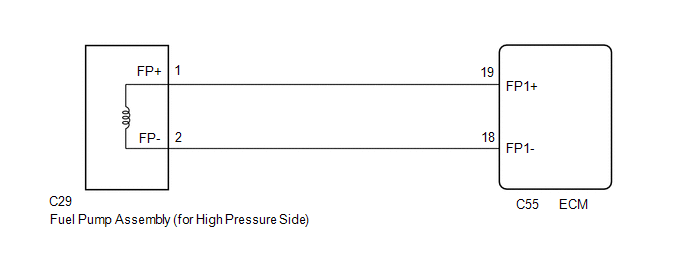
C29-1 (FP+) - C55-19 (FP1+) |
Always | Below 1 Ω |
|
C29-2 (FP-) - C55-18 (FP1-) |
Always | Below 1 Ω |
|
C29-1 (FP+) or C55-19 (FP1+) - Body ground and other terminals |
Always | 10 kΩ or higher |
|
C29-2 (FP-) or C55-18 (FP1-) - Body ground and other terminals |
Always | 10 kΩ or higher |
| OK | | REPLACE ECM |
| NG | | REPAIR OR REPLACE HARNESS OR CONNECTOR |
DESCRIPTION
Refer to DTC P001001.
Click here

|
DTC No. | Detection Item |
DTC Detection Condition | Trouble Area |
MIL | Memory |
Note |
|---|---|---|---|---|---|---|
| P136001 |
"A" Camshaft Position Actuator Bank 1 General Electrical Failure |
While engine is running, malfunction in rotation signal (VTS) of cam timing control motor with EDU assembly is detected for 3 seconds (1 trip detection logic). |
| Comes on |
DTC stored | SAE Code: P1360 |
|
Vehicle Condition | Fail-Safe |
|---|---|
| The cam timing control motor with EDU assembly is operated to the most retarded position. |
MONITOR DESCRIPTION
This DTC is output when a rotation signal malfunction is detected in the cam timing control motor with EDU assembly. While the engine is running, if a rotation signal (VTS) malfunction is detected, a DTC is immediately output (1 trip detection logic).
MONITOR STRATEGY
|
Related DTCs | P1360: Camshaft position signal range check |
|
Required sensors/Components (Main) | Cam timing control motor with EDU assembly |
|
Required sensors/Components (Related) |
- |
| Frequency of Operation |
Continuous |
| Duration |
3 seconds |
| MIL Operation |
Immediate |
| Sequence of Operation |
None |
TYPICAL ENABLING CONDITIONS
|
Monitor runs whenever the following DTCs are not stored |
None |
| All of the following conditions are met |
- |
| Auxiliary battery voltage |
11 V or higher |
| Power switch |
On (IG) |
| Engine speed |
100 rpm or higher |
| VVT motor direction calculated by camshaft position deviation |
Forward |
TYPICAL MALFUNCTION THRESHOLDS
|
VVT motor speed at VVT revolution sensor |
0 rpm or less |
CONFIRMATION DRIVING PATTERN
HINT:
Click here
Click here
Click here
HINT:
|
Techstream Display |
Description |
|---|---|
|
NORMAL |
|
|
ABNORMAL |
|
|
INCOMPLETE |
|
HINT:
The normal judgment procedure is used to complete DTC judgment and also used when clearing permanent DTCs.
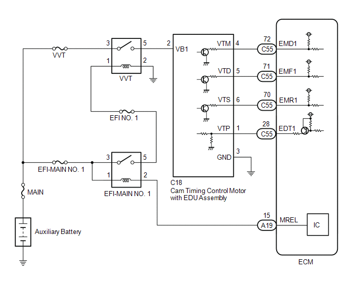
WIRING DIAGRAM
CAUTION / NOTICE / HINT
NOTICE:
Click here
(Select Powertrain in Health Check and then check the time stamp data.)
Click here
Click here
HINT:
Read Freeze Frame Data using the Techstream. The ECM records vehicle and driving condition information as Freeze Frame Data the moment a DTC is stored. When troubleshooting, Freeze Frame Data can help determine if the vehicle was moving or stationary, if the engine was warmed up or not, if the air fuel ratio was lean or rich, and other data from the time the malfunction occurred.
PROCEDURE
| 1. |
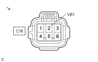
CHECK TERMINAL VOLTAGE (POWER SOURCE OF CAM TIMING CONTROL MOTOR WITH EDU ASSEMBLY) |
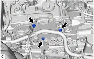
| (a) Disconnect the cam timing control motor with EDU assembly connector. |
|
(b) Turn the power switch on (IG).
(c) Measure the voltage according to the value(s) in the table below.
Standard Voltage:
|
Tester Connection | Condition |
Specified Condition |
|---|---|---|
|
C18-2 (VB1) - Body ground |
Power switch on (IG) |
11 to 14 V |
| NG |  | GO TO STEP 8 |
|
| 2. |
CHECK HARNESS AND CONNECTOR (CAM TIMING CONTROL MOTOR WITH EDU ASSEMBLY - BODY GROUND) |
(a) Disconnect the cam timing control motor with EDU assembly connector.
(b) Measure the resistance according to the value(s) in the table below.
Standard Resistance:
|
Tester Connection | Condition |
Specified Condition |
|---|---|---|
|
C18-3 (GND) - Body ground |
Always | Below 1 Ω |
| NG | | REPAIR OR REPLACE HARNESS OR CONNECTOR |
|
| 3. |
INSPECT CAM TIMING CONTROL MOTOR WITH EDU ASSEMBLY (BODY GROUND) |
(a) Check installation condition.
Torque:
21 N*m (214 kgf*cm, 15 ft.*lbf)
| NG | | TIGHTEN TO SPECIFIED TORQUE |
|
| 4. |
CHECK HARNESS AND CONNECTOR (CAM TIMING CONTROL MOTOR WITH EDU ASSEMBLY - ECM) |
(a) Disconnect the cam timing control motor with EDU assembly connector.
(b) Disconnect the ECM connector.
(c) Measure the resistance according to the value(s) in the table below.
Standard Resistance:
|
Tester Connection | Condition |
Specified Condition |
|---|---|---|
|
C18-6 (VTS) - C55-70 (EMR1) |
Always | Below 1 Ω |
|
C18-6 (VTS) or C55-70 (EMR1) - Body ground and other terminals |
Always | 10 kΩ or higher |
| NG | | REPAIR OR REPLACE HARNESS OR CONNECTOR |
|
| 5. |
REPLACE CAM TIMING CONTROL MOTOR WITH EDU ASSEMBLY |
(a) Replace the cam timing control motor with EDU assembly.
Click here
HINT:
Perform "Inspection After Repair" after replacing the cam timing control motor with EDU assembly.
Click here
|
| 6. |
CLEAR DTC |
(a) Connect the Techstream to the DLC3.
(b) Turn the power switch on (IG).
(c) Turn the Techstream on.
(d) Clear the DTCs.
Powertrain > Engine > Clear DTCs(e) Turn the power switch off and wait for at least 30 seconds.
|
| 7. |
CONFIRM WHETHER MALFUNCTION HAS BEEN SUCCESSFULLY REPAIRED |
(a) Drive the vehicle in accordance with the driving pattern described in Confirmation Driving Pattern.
(b) Enter the following menus: Powertrain / Engine / Trouble Codes.
(c) Read the DTCs.
Powertrain > Engine > Trouble Codes|
Result | Proceed to |
|---|---|
|
DTCs are not output | A |
|
DTC P136001 is output |
B |
| A |
| END |
| B |
| REPLACE ECM |
| 8. |
INSPECT VVT RELAY |
(a) Inspect the VVT relay.
Click here
| NG | | REPLACE VVT RELAY |
|
| 9. |
CHECK HARNESS AND CONNECTOR (VVT RELAY - CAM TIMING CONTROL MOTOR WITH EDU ASSEMBLY) |
(a) Remove the VVT relay from No. 1 engine room relay block and No. 1 junction block assembly.
(b) Disconnect the cam timing control motor with EDU assembly connector.
(c) Measure the resistance according to the value(s) in the table below.
Standard Resistance:
|
Tester Connection | Condition |
Specified Condition |
|---|---|---|
|
5 (VVT relay) - C18-2 (VB1) |
Always | Below 1 Ω |
|
5 (VVT relay) or C18-2 (VB1) - Body ground and other terminals |
Always | 10 kΩ or higher |
| NG | | REPAIR OR REPLACE HARNESS OR CONNECTOR |
|
| 10. |
CHECK HARNESS AND CONNECTOR (POWER SOURCE OF VVT RELAY) |
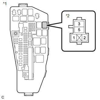
|
*1 | No. 1 Engine Room Relay Block and No. 1 Junction Block Assembly |
|
*2 | VVT Relay |
(a) Remove the VVT relay from No. 1 engine room relay block and No. 1 junction block assembly.
(b) Measure the voltage according to the value(s) in the table below.
Standard Voltage:
|
Tester Connection | Condition |
Specified Condition |
|---|---|---|
|
3 (VVT relay) - Body ground |
Always | 11 to 14 V |
| NG | | REPAIR OR REPLACE HARNESS OR CONNECTOR (AUXILIARY BATTERY - VVT RELAY) |
|
| 11. |
CHECK HARNESS AND CONNECTOR (POWER SOURCE OF VVT RELAY) |
|
*1 | No. 1 Engine Room Relay Block and No. 1 Junction Block Assembly |
|
*2 | VVT Relay |
(a) Remove the VVT relay from No. 1 engine room relay block and No. 1 junction block assembly.
(b) Turn the power switch on (IG).
(c) Measure the voltage according to the value(s) in the table below.
Standard Voltage:
|
Tester Connection | Condition |
Specified Condition |
|---|---|---|
|
1 (VVT relay) - Body ground |
Power switch on (IG) |
11 to 14 V |
| OK | | REPAIR OR REPLACE HARNESS OR CONNECTOR (VVT RELAY - BODY GROUND) |
| NG | | REPAIR OR REPLACE HARNESS OR CONNECTOR (EFI-MAIN NO. 1 RELAY - VVT RELAY) |
Toyota Avalon (XX50) 2019-2022 Owners Manual > Specifications: Fuel information
You must only use unleaded gasoline. Select octane rating 87 (Research Octane Number 91) or higher. Use of unleaded gasoline with an octane rating lower than 87 may result in engine knocking. Persistent knocking can lead to engine damage. At minimum, the gasoline you use should meet the specificati ...