DESCRIPTION
The throttle actuator is operated by the ECM and opens and closes the throttle valve using gears.
The opening angle of the throttle valve is detected by the throttle position sensor, which is mounted on the throttle body with motor assembly. The throttle position sensor provides feedback to the ECM. This feedback allows the ECM to appropriately control the throttle actuator and monitor the throttle opening angle as the ECM responds to a request from the hybrid system.
|
DTC No. | Detection Item |
DTC Detection Condition | Trouble Area |
MIL | Memory |
Note |
|---|---|---|---|---|---|---|
| P210014 |
Throttle Actuator "A" Control Motor Circuit Short to Ground or Open |
Both of the following conditions are met for 2 seconds or more (1 trip detection logic):
|
| Comes on |
DTC stored | SAE Code: P2102 |
|
P210015 | Throttle Actuator "A" Control Motor Circuit Short to Battery or Open |
Either of the following conditions is met (1 trip detection logic):
|
| Comes on |
DTC stored | SAE Code: P2103 |
MONITOR DESCRIPTION
The ECM monitors the electrical current through the electronic actuator, and detects malfunctions and open circuits in the throttle actuator based on this value. If the current is outside the standard range, the ECM determines that there is a malfunction in the throttle actuator. In addition, if the throttle valve does not operate properly (for example, it is stuck open), the ECM will determines there is a malfunction, illuminate the MIL and store a DTC.
MONITOR STRATEGY
|
Related DTCs | P2102: Electronic throttle actuator control motor range check (low current) P2103: Electronic throttle actuator control motor range check (high current) |
|
Required Sensors/Components (Main) | Throttle actuator (throttle body with motor assembly) |
|
Required Sensors/Components (Related) |
- |
| Frequency of Operation |
Continuous |
| Duration |
2 seconds: P2102 0.1 seconds: P2103 (case 1) 0.6 seconds: P2103 (case 2) |
|
MIL Operation | Immediate |
|
Sequence of Operation | None |
TYPICAL ENABLING CONDITIONS
All|
Monitor runs whenever the following DTCs are not stored |
None |
|
All of the following conditions are met |
- |
| Command to electronic throttle actuator |
On |
| Output duty cycle |
80% or higher |
| Electronic throttle actuator power supply voltage |
8 V or higher |
| Motor current change during last 0.016 seconds |
Less than 0.2 A |
|
Both of the following conditions are met |
- |
| Command to electronic throttle actuator |
On |
| Either of the following conditions is met |
1 or 2 |
| 1. Electronic throttle actuator power supply voltage |
8 V or higher |
| 2. Command to electronic throttle actuator power |
On |
TYPICAL MALFUNCTION THRESHOLDS
P2102|
Throttle actuator current | Less than 0.5 A |
|
Motor driver IC high current limiter monitor input |
Fail |
|
Motor driver IC high current inhibit signal | On |
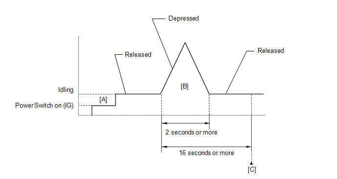
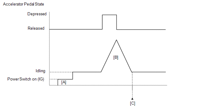
CONFIRMATION DRIVING PATTERN
HINT:
Click here 
Click here
Click here
HINT:
During charge control, the engine speed is set at idle. Therefore, the engine speed will not increase when the accelerator pedal is depressed. In this case, perform step [B] after charge control has completed.
HINT:
|
Techstream Display |
Description |
|---|---|
|
NORMAL |
|
|
ABNORMAL |
|
|
INCOMPLETE |
|
HINT:
The normal judgment procedure is used to complete DTC judgment and also used when clearing permanent DTCs.
FAIL-SAFE
When this DTC is stored, the ECM enters fail-safe mode. During fail-safe mode, the ECM cuts the current to the throttle actuator, and the throttle valve is returned to a 7.5° throttle valve opening angle by the return spring. The ECM then adjusts the engine output, by controlling the fuel injection (intermittent fuel cut) and ignition timing, in accordance with the engine torque request signal sent from the hybrid vehicle control ECU assembly, to allow the vehicle to continue being driven at a minimal speed. If the accelerator pedal is depressed firmly and gently, the vehicle can be driven slowly.
Fail-safe mode continues until a pass condition is detected, and the power switch is then turned off.
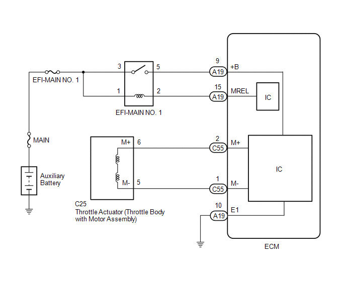
WIRING DIAGRAM
CAUTION / NOTICE / HINT
NOTICE:
Click here
(Select Powertrain in Health Check and then check the time stamp data.)
Click here
Click here
HINT:
PROCEDURE
|
1. | INSPECT THROTTLE BODY WITH MOTOR ASSEMBLY (RESISTANCE OF THROTTLE ACTUATOR) |
(a) Inspect the throttle body with motor assembly.
Click here
HINT:
Perform "Inspection After Repair" after replacing the throttle body with motor assembly.
Click here
| NG |  | REPLACE THROTTLE BODY WITH MOTOR ASSEMBLY |
|
| 2. |
CHECK HARNESS AND CONNECTOR (THROTTLE BODY WITH MOTOR ASSEMBLY - ECM) |
(a) Disconnect the throttle body with motor assembly connector.
(b) Disconnect the ECM connector.
(c) Measure the resistance according to the value(s) in the table below.
Standard Resistance:
|
Tester Connection | Condition |
Specified Condition |
|---|---|---|
|
C25-6 (M+) - C55-2 (M+) |
Always | Below 1 Ω |
|
C25-5 (M-) - C55-1 (M-) |
Always | Below 1 Ω |
|
C25-6 (M+) or C55-2 (M+) - Body ground and other terminals |
Always | 10 kΩ or higher |
|
C25-5 (M-) or C55-1 (M-) - Body ground and other terminals |
Always | 10 kΩ or higher |
| NG | | REPAIR OR REPLACE HARNESS OR CONNECTOR |
|
| 3. |
INSPECT THROTTLE BODY WITH MOTOR ASSEMBLY (VISUALLY CHECK THROTTLE VALVE) |
(a) Check for foreign matter between the throttle valve and the housing.
OK:
No foreign matter between the throttle valve and housing.
HINT:
Perform "Inspection After Repair" after cleaning the throttle body with motor assembly.
Click here
| NG | | REMOVE FOREIGN MATTER AND CLEAN THROTTLE BODY WITH MOTOR ASSEMBLY |
|
| 4. |
INSPECT THROTTLE BODY WITH MOTOR ASSEMBLY (THROTTLE VALVE) |
(a) Check if the throttle valve opens and closes smoothly.
OK:
Throttle valve opens and closes smoothly.
HINT:
Perform "Inspection After Repair" after replacing the throttle body with motor assembly.
Click here
| OK | | REPLACE ECM |
| NG | | REPLACE THROTTLE BODY WITH MOTOR ASSEMBLY |
DESCRIPTION
The idle speed is controlled by the Electronic Throttle Control System (ETCS). The ETCS is comprised of a throttle actuator, which operates the throttle valve, and a throttle position sensor, which detects the opening amount of the throttle valve. The ECM controls the throttle actuator to adjust the throttle valve opening amount so that the idle speed is maintained at the target idle speed.
|
DTC No. | Detection Item |
DTC Detection Condition | Trouble Area |
MIL | Memory |
Note |
|---|---|---|---|---|---|---|
| P210900 |
Throttle/Pedal Position Sensor "A" Minimum Stop Performance |
The ISC learned value is approximately 3 times larger than normal even though the actual intake air amount during idle is within the normal range (up to 1.5 times the normal amount) (1 trip detection logic). |
Throttle body with motor assembly |
Does not come on | DTC stored |
SAE Code: P2109 |
HINT:
MONITOR DESCRIPTION
If there are deposits in the throttle valve, a decrease in the ISC flow rate may cause engine stall or unstable idling. Therefore, the necessary ISC flow rate for idling is maintained using the ISC learned value and feedback. The ECM stores this DTC if the ISC learned value approaches its limit. The ECM begins monitoring for the DTC detection conditions when the following preconditions are met:
CAUTION / NOTICE / HINT
NOTICE:
Click here 
(Select Powertrain in Health Check and then check the time stamp data.)
Click here
Click here
HINT:
PROCEDURE
|
1. | CHECK ANY OTHER DTCS OUTPUT (IN ADDITION TO DTC P210900) |
(a) Connect the Techstream to the DLC3.
(b) Turn the power switch on (IG).
(c) Turn the Techstream on.
(d) Enter the following menus: Powertrain / Engine / Trouble Codes.
(e) Read the DTCs.
Powertrain > Engine > Trouble Codes|
Result | Proceed to |
|---|---|
|
DTC P210900 is output |
A |
| DTC P210900 and other DTCs are output |
B |
HINT:
If any DTCs other than P210900 are output, troubleshoot those DTCs first.
| B |
 | GO TO DTC CHART |
|
| 2. |
READ FREEZE FRAME DATA (ISC LEARNING VALUE) |
(a) Connect the Techstream to the DLC3.
(b) Turn the power switch on (IG).
(c) Turn the Techstream on.
(d) Using the Techstream, check "ISC Learning Value" in the Freeze Frame Data.
Powertrain > Engine > DTC(P210900) > Freeze Frame Data|
Tester Display |
|---|
| ISC Learning Value |
HINT:
Be sure to confirm that the Freeze Frame Data item "ISC Learning Value" is the same as that used when confirming whether the malfunction has been successfully repaired.
|
| 3. |
INSPECT THROTTLE BODY WITH MOTOR ASSEMBLY |
(a) Check for foreign matter between the throttle valve and the housing.
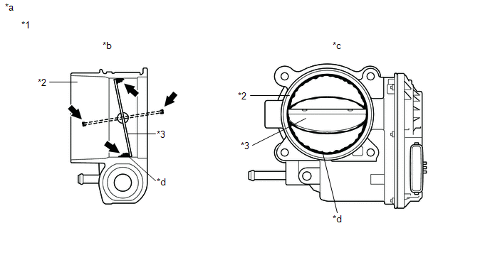
|
*1 | Throttle Body with Motor Assembly |
*2 | Bore |
|
*3 | Throttle Valve |
- | - |
|
*a | Reference |
*b | Throttle Body with Motor Assembly Cross-section Diagram |
|
*c | When valve fully opened |
*d | Deposits |
HINT:
The illustration is for reference only, actual parts may differ.
|
Result | Proceed to |
|---|---|
|
Foreign matter between the throttle valve and housing |
A |
| No foreign matter between the throttle valve and housing |
B |
HINT:
Perform "Inspection After Repair" after replacing the throttle body with motor assembly.
Click here
| B |
| REPLACE THROTTLE BODY WITH MOTOR ASSEMBLY |
|
| 4. |
REMOVE FOREIGN MATTER (CLEAN THROTTLE BODY WITH MOTOR ASSEMBLY) |
(a) Clean off any deposits inside of the throttle body with motor assembly.
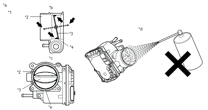
|
*1 | Throttle Body with Motor Assembly |
*2 | Bore |
|
*3 | Throttle Valve |
- | - |
|
*a | Reference |
*b | Throttle Body with Motor Assembly Cross-section Diagram |
|
*c | When valve fully opened |
*d | Do not directly apply cleaner |
|
*e | Deposits |
- | - |
(1) Push open the throttle valve and wipe off any deposits from the valve and bore using a cloth soaked in non-residue solvent.
NOTICE:
HINT:
Click here
|
| 5. |
READ VALUE USING TECHSTREAM (ISC LEARNING VALUE) |
(a) Perform "Inspection After Repair" after cleaning the throttle body with motor assembly.
Click here
(b) Connect the Techstream to the DLC3.
(c) Turn the power switch on (IG).
(d) Turn the Techstream on.
(e) Enter the following menus: Powertrain / Engine / Data List / ISC Learning Value.
Powertrain > Engine > Data List|
Tester Display |
|---|
| ISC Learning Value |
(f) According to the display on the Techstream, read the Data List.
OK:
The value of ISC Learning Value is half or less of ISC Learning Value recorded in the Freeze Frame Data.
HINT:
Perform "Inspection After Repair" after replacing the throttle body with motor assembly.
Click here
| OK | | END |
| NG | | REPLACE THROTTLE BODY WITH MOTOR ASSEMBLY |
DESCRIPTION
The throttle actuator is operated by the ECM and opens and closes the throttle valve using gears. The opening angle of the throttle valve is detected by the throttle position sensor, which is built into the throttle body with motor assembly. The throttle position sensor provides feedback to the ECM. This feedback allows the ECM to appropriately control the throttle actuator and monitor the throttle opening angle as the ECM responds to a request from the hybrid system.
|
DTC No. | Detection Item |
DTC Detection Condition | Trouble Area |
MIL | Memory |
Note |
|---|---|---|---|---|---|---|
| P211172 |
Throttle Actuator "A" Control System Actuator Stuck Open |
The ECM signals the throttle actuator to close, but the actuator is stuck (1 trip detection logic). |
| Comes on |
DTC stored | SAE Code: P2111 |
|
P211173 | Throttle Actuator "A" Control System Actuator Stuck Closed |
The ECM signals the throttle actuator to open, but the actuator is stuck (1 trip detection logic). |
| Comes on |
DTC stored | SAE Code: P2112 |
MONITOR DESCRIPTION
If the throttle valve remains at a certain angle despite a high drive current from the ECM, the ECM determines that there is a malfunction in the Electronic Throttle Control System (ETCS), illuminates the MIL and stores a DTC.
MONITOR STRATEGY
|
Related DTCs | P2111: Throttle actuator stuck open P2112: Throttle actuator stuck closed |
|
Required Sensors/Components (Main) | Throttle actuator (throttle body with motor assembly) |
|
Required Sensors/Components (Related) |
- |
| Frequency of Operation |
Continuous |
| Duration |
0.5 seconds |
| MIL Operation |
Immediate |
| Sequence of Operation |
None |
TYPICAL ENABLING CONDITIONS
P2111: Throttle Actuator Stuck Open|
All of the following conditions are met |
- |
| System guard* judge condition |
On |
| Throttle actuator current |
2 A or higher |
| Duty-cycle to close throttle |
80% or higher |
|
All of the following conditions are met | - |
|
System guard* judge condition | On |
|
Throttle actuator current | 2 A or higher |
|
Duty-cycle to open throttle | 80% or higher |
|
*: System guard set when following conditions are met |
- |
| Throttle actuator |
On |
| Throttle actuator duty calculation |
Executing |
| Throttle position sensor fail (P0121, P0122, P0123, P0222, P0223, P2135) |
Not detected |
| Throttle actuator current-cut operation |
Not executing |
| Throttle actuator power supply |
4 V or higher |
| Throttle actuator fail (P2102) |
Not detected |
TYPICAL MALFUNCTION THRESHOLDS
P2111: Throttle Actuator Stuck Open|
Throttle position sensor voltage | No change |
|
Throttle position sensor voltage | No change |
CONFIRMATION DRIVING PATTERN
HINT:
Click here 
Click here
Click here
HINT:
During charge control, the engine speed is set at idle. Therefore, the engine speed will not increase when the accelerator pedal is depressed. In this case, perform step [B] after charge control has completed.
HINT:
|
Techstream Display |
Description |
|---|---|
|
NORMAL |
|
|
ABNORMAL |
|
|
INCOMPLETE |
|
HINT:
The normal judgment procedure is used to complete DTC judgment and also used when clearing permanent DTCs.
FAIL-SAFE
When these DTCs are stored, the ECM enters fail-safe mode. During fail-safe mode, the ECM cuts the current to the throttle actuator, and the throttle valve is returned to a 7.5° throttle valve opening angle by the return spring. The ECM stops the engine and the vehicle can be driven using solely the hybrid system. If the accelerator pedal is depressed firmly and gently, the vehicle can be driven slowly.
Fail-safe mode continues until a pass condition is detected, and the power switch is then turned off.
WIRING DIAGRAM
Refer to DTC P210014.
Click here
CAUTION / NOTICE / HINT
NOTICE:
Click here
(Select Powertrain in Health Check and then check the time stamp data.)
Click here
Click here
HINT:
Click here
PROCEDURE
|
1. | CHECK ANY OTHER DTCS OUTPUT (IN ADDITION TO DTC P211172 OR P211173) |
(a) Connect the Techstream to the DLC3.
(b) Turn the power switch on (IG).
(c) Turn the Techstream on.
(d) Enter the following menus: Powertrain / Engine / Trouble Codes.
(e) Read the DTCs.
Powertrain > Engine > Trouble Codes|
Result | Proceed to |
|---|---|
|
DTC P211172 or P211173 is output |
A |
| DTC P211172 or P211173 and other DTCs are output |
B |
HINT:
If any DTCs other than P211172 or P211173 are output, troubleshoot those DTCs first.
| B |
 | GO TO DTC CHART |
|
| 2. |
INSPECT THROTTLE BODY WITH MOTOR ASSEMBLY (VISUALLY CHECK THROTTLE VALVE) |
(a) Check for foreign matter between the throttle valve and housing. If necessary, clean the throttle body with motor assembly. Also check that the throttle valve moves smoothly.
OK:
Throttle valve is not contaminated with foreign matter and moves smoothly.
HINT:
Perform "Inspection After Repair" after cleaning the throttle body with motor assembly.
Click here
| NG | | GO TO STEP 6 |
|
| 3. |
CLEAR DTC |
(a) Connect the Techstream to the DLC3.
(b) Turn the power switch on (IG).
(c) Turn the Techstream on.
(d) Clear the DTCs.
Powertrain > Engine > Clear DTCs(e) Turn the power switch off and wait for at least 30 seconds.
|
| 4. |
READ VALUE USING TECHSTREAM (THROTTLE POSITION) |
(a) Connect the Techstream to the DLC3.
(b) Turn the power switch on (IG).
(c) Turn the Techstream on.
(d) Enter the following menus: Powertrain / Engine / Data List / Throttle Position Sensor No.1 Voltage, Throttle Position Sensor No.2 Voltage and Throttle Position Command.
Powertrain > Engine > Data List|
Tester Display |
|---|
| Throttle Position Sensor No.1 Voltage |
|
Throttle Position Sensor No.2 Voltage |
|
Throttle Position Command |
(e) Read the values displayed on the Techstream while wiggling the ECM wire harness.
(f) Enter the following menus: Powertrain / Engine / Trouble Codes.
(g) Read the DTCs.
Powertrain > Engine > Trouble Codes|
Result | Proceed to |
|---|---|
|
Value in Data List changes when wire harness is wiggled, or DTC is output |
A |
| Other than above |
B |
| B |
| GO TO STEP 7 |
|
| 5. |
REPAIR OR REPLACE HARNESS OR CONNECTOR (THROTTLE BODY WITH MOTOR ASSEMBLY - ECM) |
(a) As the DTC was stored due to a change in the contact resistance of the connector, repair or replace the wire harness or connector.
Click here
| NEXT | |
END |
|
6. | REPLACE THROTTLE BODY WITH MOTOR ASSEMBLY |
(a) Replace the throttle body with motor assembly.
Click here
HINT:
Perform "Inspection After Repair" after replacing the throttle body with motor assembly.
Click here
|
| 7. |
CLEAR DTC |
(a) Connect the Techstream to the DLC3.
(b) Turn the power switch on (IG).
(c) Turn the Techstream on.
(d) Clear the DTCs.
Powertrain > Engine > Clear DTCs(e) Turn the power switch off and wait for at least 30 seconds.
|
| 8. |
CHECK WHETHER DTC OUTPUT RECURS (DTC P211172 OR P211173) |
(a) Drive the vehicle in accordance with the driving pattern described in Confirmation Driving Pattern.
(b) Enter the following menus: Powertrain / Engine / Trouble Codes.
(c) Read the DTCs.
Powertrain > Engine > Trouble Codes|
Result | Proceed to |
|---|---|
|
DTCs are not output | A |
|
DTC P211172 or P211173 is output |
B |
| A |
| END |
| B |
| REPLACE ECM |
Toyota Avalon (XX50) 2019-2022 Service & Repair Manual > Sfi System: Throttle Actuator "A" Control Throttle Body Range/Performance (P211900,P211904,P211977,P21199B)
DESCRIPTION The electronic throttle control system is composed of the throttle actuator, throttle position sensor, and ECM. The ECM operates the throttle actuator to regulate the throttle valve in response to a request from the hybrid system. The throttle position sensor detects the opening angle of ...


