DESCRIPTION
The ECM receives the low fuel level signal from the combination meter assembly (meter ECU) to detect if the vehicle is running out of fuel.
|
DTC No. | Detection Item |
DTC Detection Condition | Trouble Area |
MIL | Memory |
Note |
|---|---|---|---|---|---|---|
| P319300 |
Fuel Run Out | All of the following conditions are met (1 trip detection logic):
| - (This DTC indicates that the vehicle ran out of fuel and does not indicate the malfunction of part.) |
Does not come on | DTC stored |
SAE Code: P3193 |
MONITOR DESCRIPTION
This DTC indicates that the vehicle ran out of fuel. If the ECM receives the low fuel level signal from the combination meter assembly (meter ECU) and the DTC detection conditions of either DTC P319000 or P319100 are met while the power switch is on (IG) or the engine is operating, the ECM stores this DTC.
MONITOR STRATEGY
|
Frequency of Operation | Continuous |
CONFIRMATION DRIVING PATTERN
NOTICE:
If the MIL or a master warning light illuminates, immediately end the confirmation driving pattern. When DTCs P319000, P319100 and P319300 are output, the engine may stop. In this case, the HV battery will no longer be chargeable and the distance that the vehicle can be driven will be limited.
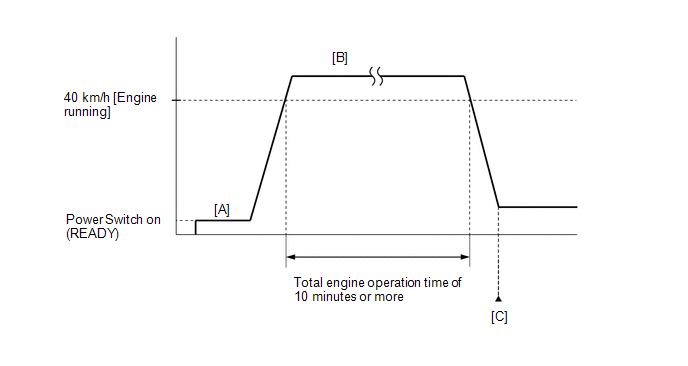
NOTICE:
As soon as the engine starts, release the accelerator pedal.
CAUTION:
When performing the confirmation driving pattern, obey all speed limits and traffic laws.
HINT:
HINT:
|
Techstream Display |
Description |
|---|---|
|
NORMAL |
|
|
ABNORMAL |
|
|
INCOMPLETE |
|
HINT:
CAUTION / NOTICE / HINT
NOTICE:
Click here 
(Select Powertrain in Health Check and then check the time stamp data.)
Click here
Click here
HINT:
In this case, after adding fuel or performing repairs, clear the DTCs. Then turn the power switch off to return to the normal condition.
PROCEDURE
|
1. | CHECK SHORTAGE OF FUEL |
(a) Check the amount of fuel remaining.
OK:
There is enough fuel.
HINT:
| OK |  | GO TO STEP 3 |
|
| 2. |
REFILL FUEL |
(a) Add fuel until the fuel level warning turns off.
|
| 3. |
CLEAR DTC |
(a) Connect the Techstream to the DLC3.
(b) Turn the power switch on (IG).
(c) Turn the Techstream on.
(d) Clear the DTCs.
Powertrain > Engine > Clear DTCs(e) Turn the power switch off and wait for at least 30 seconds.
|
| 4. |
CHECK WHETHER DTC OUTPUT RECURS |
(a) Drive the vehicle in accordance with the driving pattern described in Confirmation Driving Pattern.
(b) Enter the following menus: Powertrain / Engine / Trouble Codes.
(c) Read the DTCs.
Powertrain > Engine > Trouble Codes|
Result | Proceed to |
|---|---|
|
DTCs are not output | A |
|
DTC P319000 or P319100 is output |
B |
| DTC P319000 or P319100 and other DTCs are output |
C |
| A |
| END |
| B |
| GO TO DTC P319000, P319100 |
| C |
| GO TO DTC CHART |
PARTS LOCATION
ILLUSTRATION
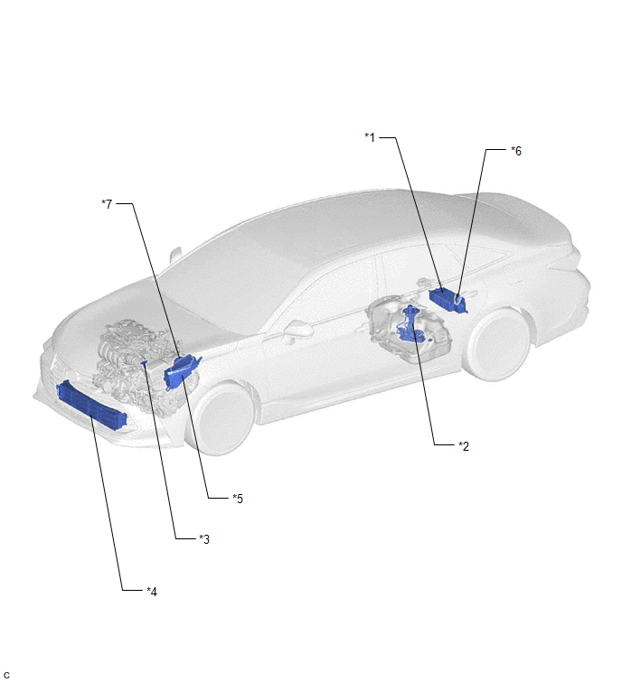
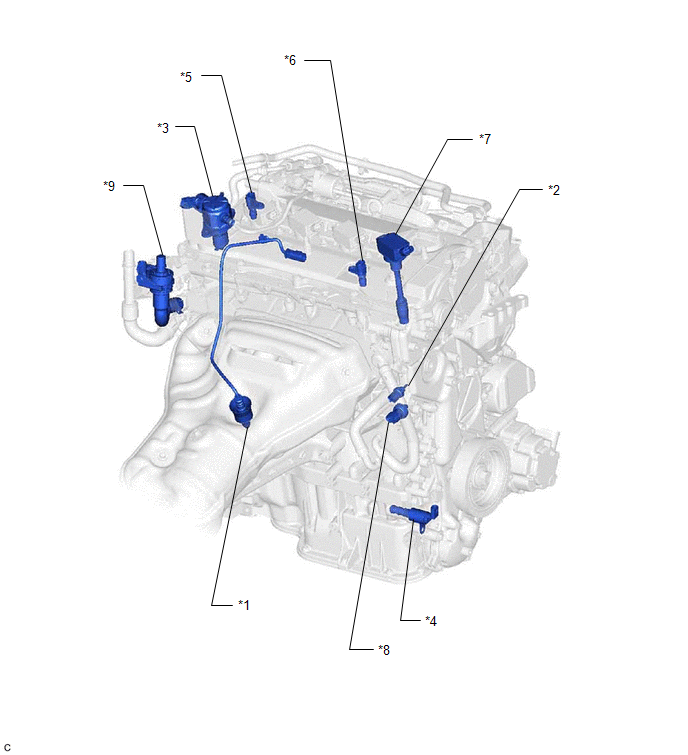
|
*1 | CANISTER |
*2 | FUEL PUMP (for Low Pressure Side) |
|
*3 | MASS AIR FLOW METER SUB-ASSEMBLY |
*4 | RADIATOR SHUTTER ASSEMBLY - RADIATOR SHUTTER SUB-ASSEMBLY - SWING GRILLE ACTUATOR ASSEMBLY |
|
*5 | NO. 1 ENGINE ROOM RELAY BLOCK AND NO. 1 JUNCTION BLOCK ASSEMBLY |
*6 | FUEL PUMP CONTROL ECU |
|
*7 | ECM |
- | - |
ILLUSTRATION
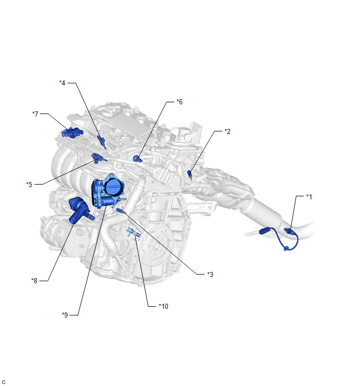
|
*1 | AIR FUEL RATIO SENSOR (Sensor 2) |
*2 | ENGINE COOLANT TEMPERATURE SENSOR |
|
*3 | NO. 2 ENGINE COOLANT TEMPERATURE SENSOR |
*4 | PORT FUEL INJECTOR ASSEMBLY |
|
*5 | DIRECT FUEL INJECTOR ASSEMBLY |
*6 | FUEL PRESSURE SENSOR (for Low Pressure Side) |
|
*7 | VACUUM SWITCHING VALVE (PURGE VSV) |
*8 | WATER INLET WITH THERMOSTAT SUB-ASSEMBLY |
|
*9 | THROTTLE BODY WITH MOTOR ASSEMBLY |
*10 | CRANKSHAFT POSITION SENSOR |
ILLUSTRATION
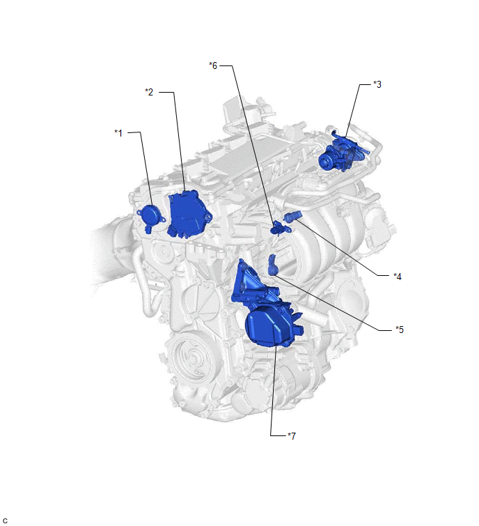
|
*1 | CAM TIMING OIL CONTROL SOLENOID ASSEMBLY |
*2 | CAM TIMING CONTROL MOTOR WITH EDU ASSEMBLY |
|
*3 | EGR VALVE ASSEMBLY |
*4 | FUEL PRESSURE SENSOR (for High Pressure Side) |
|
*5 | KNOCK CONTROL SENSOR |
*6 | MANIFOLD ABSOLUTE PRESSURE SENSOR |
|
*7 | WATER INLET HOUSING WITH WATER PUMP SUB-ASSEMBLY |
- | - |
ILLUSTRATION
|
*1 | AIR FUEL RATIO SENSOR (Sensor 1) |
*2 | ENGINE OIL TEMPERATURE SENSOR |
|
*3 | FUEL PUMP ASSEMBLY (for High Pressure Side) |
*4 | OIL PRESSURE CONTROL VALVE ASSEMBLY |
|
*5 | CAMSHAFT POSITION SENSOR (for Intake Camshaft) |
*6 | CAMSHAFT POSITION SENSOR (for Exhaust Camshaft) |
|
*7 | IGNITION COIL ASSEMBLY |
*8 | OIL PRESSURE SENSOR (OIL PRESSURE SENDER GAUGE ASSEMBLY) |
|
*9 | FLOW SHUTTING VALVE (WATER BYPASS HOSE ASSEMBLY) |
- | - |
ILLUSTRATION
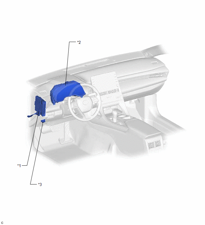
|
*1 | HYBRID VEHICLE CONTROL ECU ASSEMBLY |
*2 | COMBINATION METER ASSEMBLY |
|
*3 | DLC3 |
- | - |
PRECAUTION
WHEN USING TECHSTREAM
CAUTION:
Observe the following items for safety reasons:
INITIALIZATION
NOTICE:
Click here 
Click here
Click here
|
System Name |
See Procedure |
|---|---|
|
Lane Departure Alert System (w/ Steering Control) |
|
|
Intelligent Clearance Sonar System |
|
|
Parking Assist Monitor System |
|
|
Panoramic View Monitor System |
|
|
Pre-collision System |
|
|
Lighting System (for HV Model with Cornering Light) |
PRECAUTIONS FOR INSPECTING HYBRID CONTROL SYSTEM
(a) Refer to Hybrid Control System.
Click here
NOTICE FOR HYBRID CONTROL SYSTEM ACTIVATION
(a) Refer to Hybrid Control System.
Click here
Toyota Avalon (XX50) 2019-2022 Service & Repair Manual > Park Assist / Monitoring: Panoramic View Monitor Switch
Components COMPONENTS ILLUSTRATION *1 COWL SIDE TRIM SUB-ASSEMBLY LH *2 FRONT DOOR OPENING TRIM WEATHERSTRIP LH *3 FRONT DOOR SCUFF PLATE LH *4 HOOD LOCK CONTROL LEVER SUB-ASSEMBLY *5 INSTRUMENT SIDE PANEL LH *6 NO. 1 INSTRUMENT PANEL SUB-ASSEMBLY *7 NO. 1 INSTRUMENT PANEL UNDER COVER SUB-ASSEMBLY * ...


