DESCRIPTION
The driving support ECU assembly uses the millimeter wave radar sensor assembly to detect objects in front of the vehicle.
When the destination information in the millimeter wave radar sensor assembly and driving support ECU assembly do not match, DTC C1A0A is stored.
|
DTC No. | Detection Item |
DTC Detection Condition | Trouble Area |
MIL |
|---|---|---|---|---|
| C1A0A |
Front Radar Sensor Country Code Mismatch |
When the power switch is on (IG) and the dynamic radar cruise control system is operating, the destination information in the driving support ECU assembly and millimeter wave radar sensor assembly do not match for approximately 1.3 seconds or more. |
| Does not come on |
CAUTION / NOTICE / HINT
NOTICE:
Click here 
Click here
PROCEDURE
|
1. | CHECK FOR DTCs |
(a) Clear the DTCs.
Powertrain > Radar Cruise2 > Clear DTCs(b) Make sure that the DTC detection conditions are met.
HINT:
If the detection conditions are not met, the system cannot detect the malfunction.
(c) Check for DTCs.
Powertrain > Radar Cruise2 > Trouble Codes|
Result | Proceed to |
|---|---|
|
DTC C1A0A is not output |
A |
| DTC C1A0A is output |
B |
| A |
 | USE SIMULATION METHOD TO CHECK |
|
| 2. |
REPLACE DRIVING SUPPORT ECU ASSEMBLY |
(a) Replace the driving support ECU assembly.
Click here
|
| 3. |
CHECK FOR DTCs |
(a) Clear the DTCs.
Powertrain > Radar Cruise2 > Clear DTCs(b) Make sure that the DTC detection conditions are met.
HINT:
If the detection conditions are not met, the system cannot detect the malfunction.
(c) Check for DTCs.
Powertrain > Radar Cruise2 > Trouble Codes|
Result | Proceed to |
|---|---|
|
DTC C1A0A is not output |
A |
| DTC C1A0A is output |
B |
| A |
| END (DRIVING SUPPORT ECU ASSEMBLY WAS DEFECTIVE) |
| B |
| REPLACE MILLIMETER WAVE RADAR SENSOR ASSEMBLY |
DESCRIPTION
This DTC indicates an internal malfunction of the driving support ECU assembly.
|
DTC No. | Detection Item |
DTC Detection Condition | Trouble Area |
MIL |
|---|---|---|---|---|
| C1A01 |
Driving Support ECU | When the power switch is on (IG) and the dynamic radar cruise control system is operating, the driving support ECU assembly detects an internal malfunction for approximately 0.2 seconds or more. |
Driving support ECU assembly |
Does not come on |
CAUTION / NOTICE / HINT
NOTICE:
When replacing the driving support ECU assembly, always replace it with a new one. If a driving support ECU assembly which was installed to another vehicle is used, the information stored in the driving support ECU assembly will not match the information from the vehicle. As a result, a DTC may be stored.
PROCEDURE
| 1. |
REPLACE DRIVING SUPPORT ECU ASSEMBLY |
(a) Replace the driving support ECU assembly.
Click here 
| NEXT |  | END |
DESCRIPTION
When a new driving support ECU assembly is installed, it receives vehicle specification information (destination, steering wheel position, 2WD or AWD, etc.) from the main body ECU (multiplex network body ECU) and stores the information.
DTC C1A02 is stored when the driving support ECU assembly cannot store the vehicle specification information from the main body ECU (multiplex network body ECU).
|
DTC No. | Detection Item |
DTC Detection Condition | Trouble Area |
MIL |
|---|---|---|---|---|
| C1A02 |
Vehicle Information Not Obtained |
When the power switch is on (IG) and the dynamic radar cruise control system is operating, the driving support ECU assembly cannot store the vehicle specification information for approximately 0.1 seconds or more. |
Driving support ECU assembly |
Does not come on |
CAUTION / NOTICE / HINT
NOTICE:
When replacing the driving support ECU assembly, always replace it with a new one. If a driving support ECU assembly which was installed to another vehicle is used, the information stored in the driving support ECU assembly will not match the information from the vehicle. As a result, a DTC may be stored.
PROCEDURE
| 1. |
REPLACE DRIVING SUPPORT ECU ASSEMBLY |
(a) Replace the driving support ECU assembly.
Click here 
| NEXT |  | END |
DESCRIPTION
The driving support ECU assembly uses the millimeter wave radar sensor assembly to detect obstacles in front of the vehicle.
When the driving support ECU assembly receives information that there is a malfunction in the millimeter wave radar sensor assembly, DTC C1A10 is stored.
|
DTC No. | Detection Item |
DTC Detection Condition | Trouble Area |
MIL |
|---|---|---|---|---|
| C1A10 |
Front Radar Sensor | While the vehicle speed is 5 km/h (3 mph) or more and the dynamic radar cruise control system is operating, the driving support ECU assembly receives a malfunction signal from the millimeter wave radar sensor assembly for approximately 0.3 seconds or more. |
Millimeter wave radar sensor assembly |
Does not come on |
CAUTION / NOTICE / HINT
NOTICE:
Click here 
PROCEDURE
|
1. | REPLACE MILLIMETER WAVE RADAR SENSOR ASSEMBLY |
(a) Replace the millimeter wave radar sensor assembly with a new one.
Click here
(b) Perform millimeter wave radar sensor assembly adjustment.
Click here
| NEXT |  | END |
DESCRIPTION
The driving support ECU assembly uses the millimeter wave radar sensor assembly to detect objects in front of the vehicle.
When it is determined that the vehicle is being driven in a straight line or on a gradual curve based on signals from the yaw rate sensor, the millimeter wave radar sensor assembly performs self-diagnosis to check if the sensor beam axis has deviated. When the millimeter wave radar sensor assembly beam axis is misaligned, the driving support ECU assembly stores DTC C1A11.
After installing a new millimeter wave radar sensor assembly, if sensor beam axis adjustment is not performed, DTC C1A14 is stored.
|
DTC No. | Detection Item |
DTC Detection Condition | Trouble Area |
MIL |
|---|---|---|---|---|
| C1A11 |
Front Radar Sensor Incorrect Axial Gap |
When the vehicle is being driven at a speed of 5 km/h (3 mph) or more and the dynamic radar cruise control system is operating, misalignment of the millimeter wave radar sensor assembly is detected for approximately 0.3 seconds or more. | Pre-collision system |
Does not come on |
|
C1A14 | Front Radar Sensor Beam Axis Not Adjusted |
When the vehicle is being driven at a speed of 5 km/h (3 mph) or more and the dynamic radar cruise control system is operating, incompletion of the millimeter wave radar sensor assembly beam axis alignment is detected for approximately 0.3 seconds or more. |
Pre-collision system | Does not come on |
PROCEDURE
| 1. |
GO TO PRE-COLLISION SYSTEM |
HINT:
If DTC C1A11 or C1A14 is output by the dynamic radar cruise control system, perform troubleshooting for the pre-collision system.
Click here

| NEXT |  |
END |
DESCRIPTION
The DTC C1A52 is stored when the Hybrid vehicle control ECU cannot recognize the driving support ECU assembly.
|
DTC No. | Detection Item |
DTC Detection Condition | Trouble Area |
MIL |
|---|---|---|---|---|
| C1A52 |
Driving Support ECU Communication Abnormal |
Approximately 17 seconds after the power switch is turned on (IG), the Hybrid vehicle control ECU cannot recognize the driving support ECU assembly for approximately 1.3 seconds or more. |
Hybrid vehicle control ECU |
Does not come on |
CAUTION / NOTICE / HINT
NOTICE:
Before replacing the hybrid vehicle control ECU, refer to Registration.
Click here 
PROCEDURE
| 1. |
CHECK FOR DTCs |
(a) Clear the DTCs.
Powertrain > Radar Cruise2 > Clear DTCs(b) Make sure that the DTC detection conditions are met.
HINT:
If the detection conditions are not met, the system cannot detect the malfunction.
(c) Check for DTCs.
Powertrain > Radar Cruise2 > Trouble Codes|
Result | Proceed to |
|---|---|
|
DTC C1A52 is not output |
A |
| DTC C1A52 is output |
B |
| A |
 | USE SIMULATION METHOD TO CHECK |
| B |
| REPLACE HYBRID VEHICLE CONTROL ECU |
DESCRIPTION
When the dynamic radar cruise control system is turned on using the cruise control main switch, the cruise control indicator (vehicle-to-vehicle distance control mode) illuminates. The hybrid vehicle control ECU uses this and other indicators to indicate the control condition (presence or absence of a preceding vehicle, vehicle-to-vehicle distance, and set vehicle speed) and fail-safe state via CAN communication.
CAUTION / NOTICE / HINT
NOTICE:
Click here 
PROCEDURE
|
1. | PERFORM ACTIVE TEST USING TECHSTREAM |
(a) Connect the Techstream to the DLC3.
(b) Turn the power switch on (IG).
(c) Turn the Techstream on.
(d) Enter the following menus: Body Electrical / Combination Meter / Active Test.
(e) Perform the Active Test according to the display on the Techstream.
Body Electrical > Combination Meter > Active Test|
Tester Display | Measurement Item |
Control Range | Diagnostic Note |
|---|---|---|---|
|
Multi Display All (White) |
Multi-information display (White display) |
ON | - |
|
Tester Display |
|---|
| Multi Display All (White) |
|
Result | Proceed to |
|---|---|
|
The multi-information display in the combination meter assembly turns on according to the operation of the Active Test. |
A |
| The multi-information display in the combination meter assembly does not turn on according to the operation of the Active Test. |
B |
| B |
 | GO TO METER / GAUGE SYSTEM |
|
| 2. |
READ VALUE USING TECHSTREAM |
(a) Enter the following menus: Powertrain / Radar Cruise 1 / Data List.
(b) Read the Data List according to the display on the Techstream.
Powertrain > Radar Cruise1 > Data List|
Tester Display | Measurement Item |
Range | Normal Condition |
Diagnostic Note |
|---|---|---|---|---|
|
Cruise Indicator | Cruise control indicator status |
ON or OFF | ON: Cruise control indicator illuminates OFF: Cruise control indicator turns off |
- |
|
Tester Display |
|---|
| Cruise Indicator |
|
Result | Proceed to |
|---|---|
|
The cruise control indicator illuminates and turns off according to the operation of the cruise control main switch. |
A |
| The cruise control indicator does not illuminate but the Data List items change according to the operation of the cruise control main switch. |
B |
| The cruise control indicator does not illuminate and the Data List items do not change according to the operation of the cruise control main switch. | C |
| A |
| PROCEED TO NEXT SUSPECTED AREA SHOWN IN PROBLEM SYMPTOMS TABLE |
| B |
| REPLACE COMBINATION METER ASSEMBLY |
| C |
| REPLACE HYBRID VEHICLE CONTROL ECU |
DESCRIPTION
The hybrid vehicle control ECU illuminates the cruise SET indicator by sending indicator output demand signals to the combination meter assembly via CAN communication. The cruise SET indicator illuminates when the dynamic radar cruise control system is controlling vehicle speed. The cruise SET indicator light circuit uses CAN communication. If the cruise SET indicator is not functioning correctly, check for CAN communication DTCs before troubleshooting this circuit.
CAUTION / NOTICE / HINT
CAUTION:
Observe the following items for safety reasons when using the Techstream:
NOTICE:
Click here 
PROCEDURE
|
1. | PERFORM ACTIVE TEST USING TECHSTREAM |
(a) Connect the Techstream to the DLC3.
(b) Turn the power switch on (IG).
(c) Turn the Techstream on.
(d) Enter the following menus: Body Electrical / Combination Meter / Active Test.
(e) Perform "Active Test" according to the display on the Techstream.
Body Electrical > Combination Meter > Active Test|
Tester Display | Measurement Item |
Control Range | Diagnostic Note |
|---|---|---|---|
|
Multi Display All (White) |
Multi-information display (White display) |
ON | - |
|
Tester Display |
|---|
| Multi Display All (White) |
|
Result | Proceed to |
|---|---|
|
The multi-information display in the combination meter assembly turns on according to the operation of the Active Test. |
A |
| The multi-information display in the combination meter assembly does not turn on according to the operation of the Active Test. |
B |
| B |
 | GO TO METER / GAUGE SYSTEM |
|
| 2. |
READ VALUE USING TECHSTREAM |
(a) Turn the dynamic radar cruise control system on using the cruise control main switch.
(b) Drive at a speed between approximately 50 km/h (31 mph) and 180 km/h (112 mph).
(c) Enter the following menus: Powertrain / Radar Cruise 1 / Data List.
(d) Read the Data List according to the display on the Techstream.
Powertrain > Radar Cruise1 > Data List|
Tester Display | Measurement Item |
Range | Normal Condition |
Diagnostic Note |
|---|---|---|---|---|
|
-SET Switch | -SET switch signal |
ON or OFF | ON: -SET switch pushed OFF: -SET switch not pushed |
- |
|
Tester Display |
|---|
| -SET Switch |
|
Result | Proceed to |
|---|---|
|
The cruise SET indicator illuminates and turns off according to the operation of the -SET switch. |
A |
| The cruise SET indicator does not illuminate but the Data List item -SET Switch changes according to the operation of the -SET switch. |
B |
| The cruise SET indicator does not illuminate and the Data List item -SET Switch does not change according to the operation of the -SET switch. |
C |
| A |
| PROCEED TO NEXT SUSPECTED AREA SHOWN IN PROBLEM SYMPTOMS TABLE |
| B |
| REPLACE COMBINATION METER ASSEMBLY |
| C |
| REPLACE HYBRID VEHICLE CONTROL ECU |
DATA LIST / ACTIVE TEST
DATA LIST
NOTICE:
In the table below, the values listed under "Normal Condition" are reference values. Do not depend solely on these reference values when deciding whether a part is faulty or not.
HINT:
Using the Techstream to read the Data List allows the values or states of switches, sensors, actuators and other items to be read without removing any parts. This non-intrusive inspection can be very useful because intermittent conditions or signals may be discovered before parts or wiring is disturbed. Reading the Data List information early in troubleshooting is one way to save diagnostic time.
(a) Connect the Techstream to the DLC3.
(b) Turn the power switch on (IG).
(c) Turn the Techstream on.
(d) Enter the following menus: Powertrain / Radar Cruise 1*1 or Radar Cruise 2*2 / Data List.
(e) Radar Cruise 1:
Read the Data List according to the display on the Techstream.
HINT:
|
Tester Display | Measurement Item |
Range | Normal Condition |
Diagnostic Note |
|---|---|---|---|---|
|
Cruise Vehicle Speed | Vehicle speed |
Min.: 0 km/h (0 mph), Max.: 255 km/h (158 mph) |
Actual vehicle speed |
- |
| Cruise Memory Vehicle Speed |
Stored vehicle speed | Min.: 0 km/h (0 mph), Max.: 255 km/h (158 mph) |
Stored vehicle speed |
- |
| Cruise Request Throttle Opening Angle |
Cruise requested position |
0 to 124.99 deg | When cruise is set (vehicle in motion at 80 km/h (50 mph)): Actual requested throttle position |
- |
| Vehicle Acceleration |
Acceleration condition while driving the vehicle |
-13.10 to 13.10 m/s2 | Current value displayed |
- |
| Cruise Target Acceleration |
Target acceleration while in cruise control mode |
-13.10 to 13.10 m/s2 | Current value displayed |
- |
| Driving Support ECU Target Acceleration |
- | - |
- | - |
|
Acceleration Continuation Decision |
- | - |
- | - |
|
Output Driving Force |
- | - |
- | - |
|
Cruise Request Driving Force |
Cruise request torque signal |
-10.00 to 9.92 kN | Differs according to the cruise control system condition |
- |
| Cruise Request Driving Force Feedback Status |
- | - |
- | - |
|
Cruise Control Permission Condition |
- | - |
- | - |
|
Cruise Control Condition |
- | - |
- | - |
|
Cruise Control Mode | Cruise control mode condition |
Vehicle Distance Control Mode (All Speed), Vehicle Distance Control Mode or Constant Speed Control Mode |
Vehicle Distance Control Mode (All Speed): Vehicle distance control mode (All Speed) operating Vehicle Distance Control Mode: Vehicle distance control mode operating Constant Speed Control Mode: Constant speed control mode operating |
- |
| Cruise Request Gear Position |
Shift request from hybrid vehicle control ECU |
None or 255 Gear | Shift request from cruise control system |
- |
| Cruise Acceleration and Deceleration Operation Condition |
- | - |
- | - |
|
Cancel Switch | CANCEL switch status |
ON or OFF | ON: CANCEL switch pushed OFF: CANCEL switch not pushed |
- |
| -SET Switch |
-SET switch status | ON or OFF |
ON: -SET switch pushed OFF: -SET switch not pushed |
- |
| +RES Switch |
+RES switch status | ON or OFF |
ON: +RES switch pushed OFF: +RES switch not pushed |
- |
| Cruise Main Switch Operation Condition |
Cruise control main switch status |
ON or OFF | ON: Cruise control main switch pushed OFF: Cruise control main switch not pushed |
- |
| Cruise Ready Main-CPU |
Cruise control system standby condition |
ON or OFF | ON: Cruise control main switch pushed OFF: Cruise control main switch not pushed |
- |
| Cruise Ready Sub-CPU |
Cruise control system standby condition |
ON or OFF | ON: Cruise control main switch pushed OFF: Cruise control main switch not pushed |
- |
| Accelerator Pedal |
Condition of the accelerator pedal during cruising |
ON or OFF | ON: Accelerator pedal depressed OFF: Accelerator pedal released |
- |
| Cruise Brake Cancel Switch |
Cruise control brake cancel condition |
ON or OFF | ON: Brake pedal depressed OFF: Brake pedal released |
- |
| Stop Light Switch Main-CPU |
Stop light switch signal |
ON or OFF | ON: Brake pedal depressed OFF: Brake pedal released |
- |
| Stop Light Switch Sub-CPU |
- | - |
- | - |
|
Request Manual Cancel |
- | - |
- | - |
|
Request Automatic Cancel |
- | - |
- | - |
|
Cruise Brake Control Decision |
Cruise brake control decision |
ON or OFF | ON: Cruise brake activated OFF: Cruise brake deactivated |
- |
| Cruise Brake Control Permission Condition |
- | - |
- | - |
|
Cruise Indicator | Cruise control indicator status |
ON or OFF | ON: Cruise control indicator illuminates OFF: Cruise control indicator turns off |
- |
| Wheel Speed Sensor and Deceleration Sensor |
Speed sensor signal and deceleration sensor signal condition |
Avail or Not Avl | Avail: Speed sensor signal and deceleration sensor signal available Not Avl: Speed sensor signal and deceleration sensor signal not available |
- |
| Gradient of Road Surface |
- | - |
- | - |
(f) Radar Cruise 2:
Read the Data List according to the display on the Techstream.
HINT:
|
Tester Display | Measurement Item |
Range | Normal Condition |
Diagnostic Note |
|---|---|---|---|---|
|
Cruise Control Main Switch |
Cruise control main switch signal |
ON or OFF | ON: Cruise control main switch pushed OFF: Cruise control main switch not pushed |
- |
| Distance Control Switch |
Distance control switch signal |
ON or OFF | ON: Distance control switch on OFF: Distance control switch off |
- |
| Cruise Control Mode |
Cruise control mode signal |
All Spd, Hi Spd or Normal |
All Spd: Vehicle-to-vehicle distance control mode (w/ Full-speed Range Following Function) Hi Spd: Vehicle-to-vehicle distance control mode (w/o Full-speed Range Following Function) Normal: Constant speed mode |
- |
| Vehicle Distance |
Distance to preceding vehicle |
Min.: 0 m (0 ft.), Max.: 255 m (836.65 ft.) |
Actual distance to vehicle |
- |
| Vhcl Spd-Brake ECU |
Vehicle speed from skid control ECU |
Min.: -327.0 km/h (-203 mph), Max.: 327.0 km/h (204 mph) |
Actual vehicle speed |
- |
| Vehicle Acceleration |
Vehicle acceleration | Min.: -5.00 m/s2, Max.: 5.00 m/s2 |
Actual vehicle acceleration |
- |
| Closed Throttle Position |
Accelerator pedal idle position signal |
ON or OFF | ON: Accelerator pedal released OFF: Accelerator pedal depressed |
- |
| Yaw Rate Sensor |
Yaw rate value | Min.: -100.00 deg/s Max.: 100.00 deg/s | Actual yaw rate value |
- |
| Forward Vhcl Relative Spd |
Vehicle ahead relative speed |
Min.: -128 m/s, Max.: 127 m/s |
Actual vehicle ahead relative speed |
- |
| Vehicle Approach Warning |
Forward vehicle approach warning signal |
ON or OFF | ON: Forward vehicle approaching OFF: Forward vehicle not approaching |
- |
| CCS System Check |
Dynamic radar cruise control system warning indication |
ON or OFF | ON: Dynamic radar cruise control system warning indication (Malfunction detected) OFF: Dynamic radar cruise control system warning indication (Malfunction not detected) |
- |
| FRS-Dirt |
History of dirt detected on millimeter wave radar sensor assembly |
ON or OFF | ON: History of dirt detected on millimeter wave radar sensor assembly OFF: No history of dirt detected on millimeter wave radar sensor assembly |
- |
| Bad Wthr Hist(F Radar Sen) |
History of millimeter wave radar sensor assembly detecting bad weather |
ON or OFF | ON: History of millimeter wave radar sensor assembly detecting bad weather OFF: No history of millimeter wave radar sensor assembly detecting bad weather |
- |
| Frnt Radar Sens Temp Hi |
Millimeter wave radar sensor assembly high temperature abnormality |
ON or OFF | ON: Millimeter wave radar sensor assembly abnormal OFF: Millimeter wave radar sensor assembly normal |
- |
| Front Radar Voltage |
Millimeter wave radar sensor assembly low voltage abnormality |
Normal or Low | Normal: Millimeter wave radar sensor assembly normal Low: Millimeter wave radar sensor assembly abnormal |
- |
| Driving Support ECU Destination Variation No |
Destination variation number for driving support ECU assembly |
Variation number or Not Available |
Actual variation number |
- |
| Front Radar Sensor Destination Variation No |
Destination variation number for millimeter wave radar sensor |
Variation number or Not Available |
Actual variation number |
- |
| Steering Angle |
Steering sensor signal |
Min.: -3072.0 deg, Max.: 3070.5 deg |
Increase: Turning left Decrease: Turning right |
- |
| Zero Point Angle Sens |
Zero point steering angle sensor |
Min.: -3072.0 deg, Max.: 3070.5 deg |
Actual zero point steering angle |
- |
| Radar |
Millimeter wave radar sensor assembly operation signal |
Stop or Emission | Stop: Millimeter wave radar sensor assembly signal stopped Emission: Millimeter wave radar sensor assembly signal sent |
- |
| # Codes |
Number of DTC | Min.: 0, Max.: 255 |
Actual number of DTCs |
- |
(g) Enter the following menus: Chassis / ABS/VSC/TRAC / Data List.
(h) Read the Data List according to the display on the Techstream.
Chassis > ABS/VSC/TRAC > Data List|
Tester Display | Measurement Item |
Range | Normal Condition |
Diagnostic Note |
|---|---|---|---|---|
|
Stop Light SW | Stop light switch assembly |
ON or OFF | ON: Brake pedal depressed OFF: Brake pedal released |
- |
| Stop Light Relay |
Stop light control relay (Stop light switch assembly) (STP2 terminal input) |
ON or OFF | ON: Brake pedal depressed OFF: Brake pedal released |
- |
ACTIVE TEST
HINT:
Using the Techstream to perform Active Tests allows relays, VSVs, actuators and other items to be operated without removing any parts. This non-intrusive functional inspection can be very useful because intermittent operation may be discovered before parts or wiring is disturbed. Performing Active Tests early in troubleshooting is one way to save diagnostic time. Data List information can be displayed while performing Active Tests.
Perform Active Test according to the display on the Techstream.
(a) Connect the Techstream to the DLC3.
(b) Turn the power switch on (IG).
(c) Turn the Techstream on.
(d) Enter the following menus: Powertrain / Radar Cruise 2 / Active Test.
(e) Perform Active Test according to the display on the Techstream.
HINT:
The power switch must be turned on (IG) to proceed with the Active Test using the Techstream.
Powertrain > Radar Cruise2 > Active Test|
Tester Display | Measurement Item |
Control Range | Diagnostic Note |
|---|---|---|---|
|
Radar Cruise Stop Buzzer |
Radar cruise stop buzzer (stop sound) |
ON or OFF | Test possible at vehicle speed of 0 km/h (0 mph) |
|
Radar Cruise Approach Alarm Buzzer |
Radar cruise approach alarm buzzer (approach sound) |
ON or OFF | Test possible at vehicle speed of 0 km/h (0 mph) |
(f) Enter the following menus: Body Electrical / Combination Meter / Active Test.
(g) Perform Active Test according to the display on the Techstream.
HINT:
The power switch must be turned on (IG) to proceed with the Active Test using the Techstream.
Body Electrical > Combination Meter > Active Test|
Tester Display | Measurement Item |
Control Range | Diagnostic Note |
|---|---|---|---|
|
Multi Display All (White) |
Multi-information display (White display) |
ON | - |
(h) Enter the following menus: Chassis / ABS/VSC/TRAC / Active Test.
(i) Perform Active Test according to the display on the Techstream.
HINT:
The power switch must be turned on (IG) to proceed with the Active Test using the Techstream.
Chassis > ABS/VSC/TRAC > Active Test|
Tester Display | Measurement Item |
Control Range | Diagnostic Note |
|---|---|---|---|
|
Stop Light Relay | Stop light control relay (Stop light switch assembly) |
Relay ON/OFF | Stop lights come on |
DEFINITION OF TERMS
|
Term | Definition |
|---|---|
|
Monitor description | Description of what the hybrid vehicle control ECU monitors and how it detects malfunctions (monitoring purpose and details). |
|
Related DTCs | Group of diagnostic trouble codes that are output by the hybrid vehicle control ECU based on the same malfunction detection logic. |
|
Typical enabling conditions | Preconditions that allow the hybrid vehicle control ECU to detect malfunctions. With all preconditions satisfied, the hybrid vehicle control ECU stores a DTC when the monitored value(s) exceeds the malfunction threshold(s). |
|
Sequence of operation | The priority order that is applied to monitoring if multiple sensors and components are used to detect the malfunction. While one sensor is being monitored, the next sensor or component will not be monitored. |
|
Required sensors/Components | The sensors and components that are used by the hybrid vehicle control ECU to detect malfunctions. |
|
Frequency of operation | The number of times that the hybrid vehicle control ECU checks for malfunctions per driving cycle. "Once per driving cycle" means that the hybrid vehicle control ECU detects a malfunction only once during a single driving cycle. "Continuous" means that the hybrid vehicle control ECU detects a malfunction every time the enabling conditions are met. |
|
Duration | The minimum time for which the hybrid vehicle control ECU must detect a continuous deviation in the monitored value(s) in order to store a DTC. Timing begins after the "typical enabling conditions" are met. |
|
Typical malfunction thresholds | Value beyond which the hybrid vehicle control ECU will determine that there is a malfunction and stores a DTC. |
|
MIL operation | MIL illumination timing after a malfunction is detected. "Immediate" means that the hybrid vehicle control ECU illuminates the MIL the instant the hybrid vehicle control ECU determines that there is a malfunction. "2 driving cycles" means that the hybrid vehicle control ECU illuminates the MIL if the same malfunction is detected again in the next driving cycle. |
|
Component operating range |
Normal operation range of sensors and solenoids under normal driving conditions. Use these ranges as a reference. The ranges cannot be used to judge if a sensor or solenoid is defective or not. |
DIAGNOSIS SYSTEM
DIAGNOSIS FUNCTION
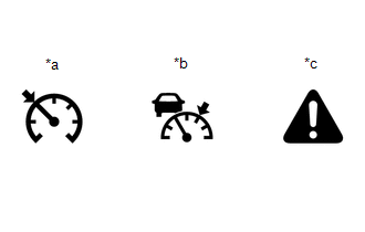
(a) The diagnosis function turns off the cruise control indicator, illuminates the master warning light and displays a warning message when a malfunction is detected. When a malfunction is detected in the dynamic radar cruise control system, DTCs are stored in the hybrid vehicle control ECU or driving support ECU assembly.
|
*a | Cruise Control Indicator (Constant Speed Control Mode) |
|
*b | Cruise Control Indicator (Vehicle-to-vehicle Distance Control Mode) |
|
*c | Master Warning Light |
NOTICE:
DESCRIPTION
(a) The hybrid vehicle control ECU and driving support ECU assembly control the dynamic radar cruise control system of the vehicle. The data and DTCs relating to the dynamic radar cruise control system can be read from the DLC3 of the vehicle. Use the Techstream to check and solve the problem.
CHECK DLC3
(a) Check the DLC3.
Click here

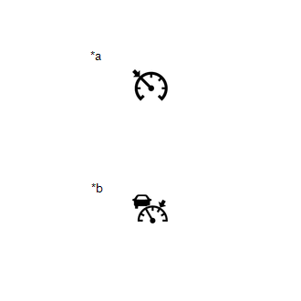
CHECK INDICATOR
(a) Turn the power switch on (IG).
(b) Check that the cruise control indicator illuminates when the dynamic radar cruise control system is turned on using the cruise control main switch, and that the indicator turns off when the dynamic radar cruise control system is turned off using the cruise control main switch.
|
*a | Cruise Control Indicator (Constant Speed Control Mode) |
|
*b | Cruise Control Indicator (Vehicle-to-vehicle Distance Control Mode) |
DIAGNOSTIC TROUBLE CODE CHART
Dynamic Radar Cruise Control System|
DTC No. | Detection Item |
MIL | Link |
|---|---|---|---|
|
C1A01 | Driving Support ECU |
Does not come on |
|
|
C1A02 | Vehicle Information Not Obtained |
Does not come on |
|
|
C1A0A | Front Radar Sensor Country Code Mismatch |
Does not come on |
|
|
C1A10 | Front Radar Sensor |
Does not come on |
|
|
C1A11 | Front Radar Sensor Incorrect Axial Gap |
Does not come on |
|
|
C1A14 | Front Radar Sensor Beam Axis Not Adjusted |
Does not come on |
|
|
C1A52 | Driving Support ECU Communication Abnormal |
Does not come on |
|
|
P057113 | Brake Switch "A" Circuit Open |
Does not come on |
|
|
P057162 | Brake Switch "A" Signal Compare Failure |
Does not come on |
|
|
P057504 | Cruise Control System Internal Failure |
Does not come on |
|
|
P057549 | Cruise Control Internal Electronic Failure |
Does not come on |
|
|
P157800 | Brake System |
Does not come on |
|
|
P160700 | Cruise Control Input Processor |
Comes on |
|
|
P163081 | Communication Error from VSC to ECM Invalid Serial Data Received |
Does not come on |
|
|
P163181 | Communication Error from ECM to VSC Invalid Serial Data Received |
Does not come on |
|
|
U012287 | Lost Communication with Vehicle Dynamics Control Module Missing Message |
Does not come on |
|
|
U0125 | Lost Communication with Yaw Rate Sensor Module |
Does not come on |
|
|
U0126 | Lost Communication with Steering Angle Sensor Module |
Does not come on |
|
|
U0129 | Lost Communication with Brake System Control Module |
Does not come on |
|
|
U0235 | Lost Communication with Cruise Control Front Distance Range Sensor |
Does not come on |
|
|
U0293 | Lost Communication with Hybrid Vehicle Control System |
Does not come on |
|
|
U029387 | Lost Communication With Hybrid Powertrain Control Module Missing Message |
Does not come on |
|
|
U1104 | Lost Communication with Driving Support ECU |
Does not come on |
|
|
U110487 | Lost Communication with Driving Support ECU Missing Message |
Does not come on |
|
DESCRIPTION
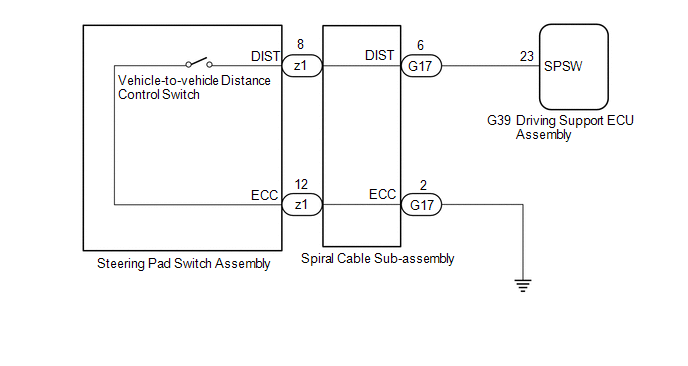
The vehicle-to-vehicle distance control switch is used to set the distance for vehicle-to-vehicle distance control mode. The vehicle-to-vehicle distance control switch is installed in the steering pad switch assembly. The vehicle-to-vehicle distance set value can be changed by operating the vehicle-to-vehicle distance control switch while the dynamic radar cruise control system is controlling vehicle speed in vehicle-to-vehicle distance control mode.
WIRING DIAGRAM
CAUTION / NOTICE / HINT
NOTICE:
Click here 
PROCEDURE
|
1. | READ VALUE USING TECHSTREAM |
(a) Connect the Techstream to the DLC3.
(b) Turn the power switch on (IG).
(c) Turn the Techstream on.
(d) Enter the following menus: Powertrain / Radar Cruise 2 / Data List.
(e) Read the Data List according to the display on the Techstream.
Powertrain > Radar Cruise2 > Data List|
Tester Display | Measurement Item |
Range | Normal Condition |
Diagnostic Note |
|---|---|---|---|---|
|
Distance Control Switch |
Distance control switch signal |
ON or OFF | ON: Distance control switch on OFF: Distance control switch off |
- |
|
Tester Display |
|---|
| Distance Control Switch |
OK:
When the vehicle-to-vehicle distance control switch is operated, the display changes as shown above.
| OK |  | PROCEED TO NEXT SUSPECTED AREA SHOWN IN PROBLEM SYMPTOMS TABLE |
|
| 2. |
INSPECT STEERING PAD SWITCH ASSEMBLY |
(a) Remove the steering pad switch assembly.
Click here
(b) Inspect the steering pad switch assembly.
Click here
| NG | | REPLACE STEERING PAD SWITCH ASSEMBLY |
|
| 3. |
INSPECT SPIRAL CABLE SUB-ASSEMBLY |
(a) Remove the spiral cable sub-assembly.
Click here
(b) Inspect the spiral cable sub-assembly.
Click here
| NG | | REPLACE SPIRAL CABLE SUB-ASSEMBLY |
|
| 4. |
CHECK HARNESS AND CONNECTOR (SPIRAL CABLE SUB-ASSEMBLY - DRIVING SUPPORT ECU ASSEMBLY AND BODY GROUND) |
(a) Disconnect the G17 spiral cable sub-assembly connector.
(b) Disconnect the G39 driving support ECU assembly connector.
(c) Measure the resistance according to the value(s) in the table below.
Standard Resistance:
|
Tester Connection | Condition |
Specified Condition |
|---|---|---|
|
G17-6 (DIST) - G39-23 (SPSW) |
Always | Below 1 Ω |
|
G17-2 (ECC) - Body ground |
Always | Below 1 Ω |
|
G17-6 (DIST) or G39-23 (SPSW) - Body ground |
Always | 10 kΩ or higher |
(d) Connect the G39 driving support ECU assembly connector.
(e) Connect the G17 spiral cable sub-assembly connector.
| OK | | REPLACE DRIVING SUPPORT ECU ASSEMBLY |
| NG | | REPAIR OR REPLACE HARNESS OR CONNECTOR |
DTC CHECK / CLEAR
NOTICE:
When the diagnosis system is changed from normal mode to check mode or vice versa, all DTCs and freeze frame data recorded in normal mode are cleared. Before changing modes, always check and make a note of DTCs and freeze frame data.
HINT:
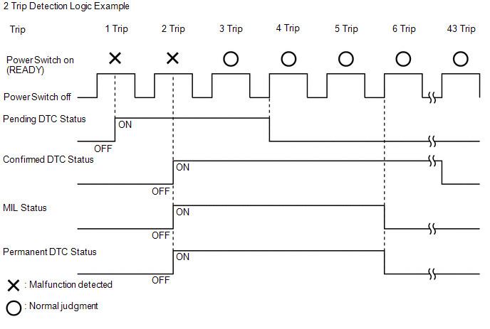
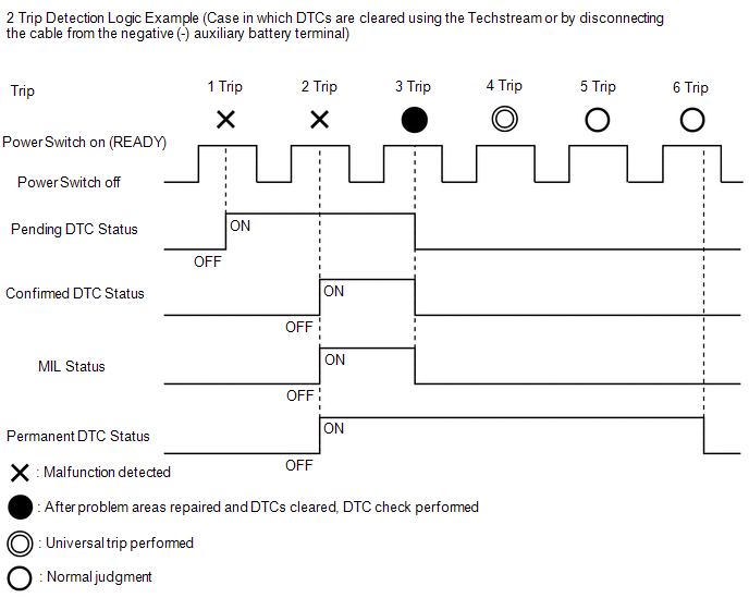
To clear permanent DTCs, all of the following conditions must be met:
|
Pending DTC | Store condition |
Malfunction detected |
| Clear condition |
System determined to be normal or DTCs cleared using Techstream or Cable disconnected from negative (-) auxiliary battery terminal | |
|
Confirmed DTC | Store condition |
Malfunction detected (2nd trip) |
|
Clear condition | No malfunctions in 40 driving cycles or DTCs cleared using Techstream or Cable disconnected from negative (-) auxiliary battery terminal | |
|
Permanent DTC | Store condition |
Malfunction detected (2nd trip) |
|
Clear condition | Power switch is turned on (IG) after normal judgment obtained in 3 consecutive driving cycles or After DTCs cleared using Techstream or cable disconnected from negative (-) auxiliary battery terminal, universal trip performed and normal judgment obtained for 2 trips (not for misfire and fuel system DTCs) or After DTCs cleared using Techstream or cable disconnected from negative (-) auxiliary battery terminal, malfunction not detected when universal trip driving performed (misfire and fuel system DTCs) | |
|
MIL | ON | Malfunction detected (2nd trip) |
|
OFF | Power switch is turned on (IG) after normal judgment obtained in 3 consecutive driving cycles or DTCs cleared using Techstream or Cable disconnected from negative (-) auxiliary battery terminal |
HINT:
CHECK DTC
(a) Connect the Techstream to the DLC3.
(b) Turn the power switch on (IG).
(c) Turn the Techstream on.
(d) Enter the following menus: Powertrain / Radar Cruise 1*1 or Radar Cruise 2*2 / Trouble Codes.
(e) Check for DTCs.
Powertrain > Radar Cruise1 > Trouble Codes Powertrain > Radar Cruise2 > Trouble CodesCLEAR DTC (Pending and Confirmed DTC)
(a) Connect the Techstream to the DLC3.
(b) Turn the power switch on (IG).
(c) Turn the Techstream on.
(d) Enter the following menus: Powertrain / Radar Cruise 1*1 or Radar Cruise 2*2 / Clear DTCs.
(e) Clear the DTCs.
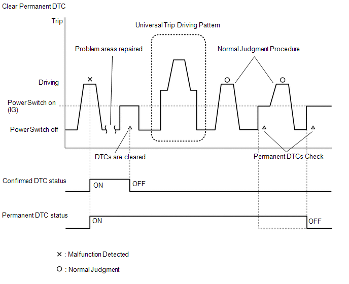
Powertrain > Radar Cruise1 > Clear DTCs Powertrain > Radar Cruise2 > Clear DTCsCLEAR PERMANENT DTC
OUTLINE(a) Connect the Techstream to the DLC3.
(b) Turn the power switch on (IG).
(c) Turn the Techstream on.
(d) Enter the following menus: Powertrain / Radar Cruise 1 / Trouble Codes.
Powertrain > Radar Cruise1 > Trouble CodesHINT:
If "YES" is displayed for the value of "PERMANENT" at the top right of the Techstream screen, permanent DTCs are stored.
(e) Select the "Generic" tab.
(f) Check if permanent DTCs are stored.
HINT:
If permanent DTCs are not output, it is not necessary to continue this procedure.
(g) Clear the DTCs (even if no DTCs are stored, perform the clear DTC procedure).
Powertrain > Radar Cruise1 > Clear DTCsNOTICE:
Do not clear the DTCs or disconnect the cable from the auxiliary battery terminal after performing this step.
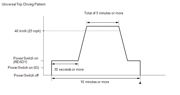
(h) Perform the universal trip.
CAUTION:
When performing the driving pattern, obey all speed limits and traffic laws.
HINT:
The universal trip driving pattern and normal judgment procedure can be performed consecutively in the same driving cycle.
HINT:
It is possible to complete the drive pattern even if the vehicle decelerates to less than 40 km/h (25 mph) during the driving cycle provided that the vehicle is driven at 40 km/h (25 mph) or more for a total of 5 minutes.
(i) Turn the power switch off and wait for 2 minutes or more.
(j) Perform the normal judgment procedure in the respective confirmation driving pattern of each output DTC.
HINT:
Do not turn the power switch off by mistake during this step.
(k) With power switch on (READY) and wait for 5 seconds or more.
(l) Turn the power switch off and wait for 2 minutes or more.
(m) Turn the power switch on (IG).
(n) Enter the following menus: Powertrain / Radar Cruise 1 / Trouble Codes.
Powertrain > Radar Cruise1 > Trouble Codes(o) Check that the permanent DTCs have been cleared.
HINT:
If permanent DTCs are not output, it is not necessary to continue this procedure.
(p) Perform the normal judgment procedure in the respective confirmation driving pattern of each output DTC.
HINT:
Do not turn the power switch off by mistake during this step.
(q) With power switch on (READY) and wait for 5 seconds or more.
(r) Turn the power switch off and wait for 2 minutes or more.
(s) Turn the power switch on (IG).
(t) Enter the following menus: Powertrain / Radar Cruise 1 / Trouble Codes.
Powertrain > Radar Cruise1 > Trouble Codes(u) Check that the permanent DTCs have been cleared.
HINT:
Permanent DTCs will be cleared if a normal judgment is obtained during 3 consecutive driving cycles with the MIL illuminated.
FAIL-SAFE CHART
HINT:
If any of the following auto cancel conditions are detected while the dynamic radar cruise control system is controlling vehicle speed, the system clears the stored vehicle speed and cancels control of vehicle speed by the dynamic radar cruise control system.
Automatic Cancel Control
Constant Speed Control Mode:|
Auto Cancel Condition |
Warning | Fail-safe Deactivation Condition | |||
|---|---|---|---|---|---|
|
Multi-information Display |
Master Warning Light |
Cruise Control Indicator |
Warning Buzzer | ||
| Open or short in stop light switch circuit |
Cruise Control Malfunction Visit Your Dealer |
Illuminates | Does not illuminate |
Sounds | Dynamic radar cruise control system is turned off and back on again using the cruise control main switch. |
| Cruise Control Malfunction Visit Your Dealer |
Illuminates | Does not illuminate |
Sounds | Power switch is turned off and back on (IG) again. |
|
If the following condition occurs, the hybrid vehicle control ECU cancels control of vehicle speed by the dynamic radar cruise control system (stored vehicle speed is maintained):
| - |
Does not illuminate | Illuminates |
- | +RES switch is pushed. |
|
Malfunction in hybrid control system |
- | Illuminates |
Does not illuminate | - |
Dynamic radar cruise control system is turned off and back on again using the cruise control main switch. |
|
Vehicle speed is less than stored vehicle speed by approximately 16 km/h (10 mph) or more |
- | Does not illuminate |
Illuminates | - |
-SET switch is pushed. |
| - |
Does not illuminate | Illuminates |
- | +RES switch is pushed. |
|
Auto Cancel Condition |
Warning | Fail-safe Deactivation Condition | |||
|---|---|---|---|---|---|
|
Multi-information Display |
Master Warning Light |
Cruise Control Indicator |
Warning Buzzer | ||
| *1: for Speedometer with Imperial Units for Main Scale | |||||
| Open or short in stop light switch circuit |
Cruise Control Malfunction Visit Your Dealer |
Illuminates | Does not illuminate |
Sounds | Dynamic radar cruise control system is turned off and back on again using the cruise control main switch. |
|
Malfunction in hybrid control system |
- | Illuminates |
Does not illuminate | - |
Dynamic radar cruise control system is turned off and back on again using the cruise control main switch. |
|
If either of the following conditions occurs, the hybrid vehicle control ECU cancels control of vehicle speed by the dynamic radar cruise control system (stored vehicle speed is maintained):
| - |
Does not illuminate | Illuminates |
Sounds | +RES switch is pushed. |
| Cruise Control Malfunction Visit Your Dealer |
Illuminates | Does not illuminate |
Sounds | Power switch is turned off and back on (IG) again. |
|
If the following condition occurs, the hybrid vehicle control ECU cancels control of vehicle speed by the dynamic radar cruise control system (stored vehicle speed is maintained):
| Radar Cruise Control Unavailable Clean Sensor |
Illuminates | Does not illuminate |
Sounds | The condition returns to normal (the resume function can be operated after fail-safe is deactivated). |
|
If any of the conditions listed below occurs, the hybrid vehicle control ECU cancels control of vehicle speed by the dynamic radar cruise control system (stored vehicle speed is maintained):
| Radar Cruise Control Unavailable |
Illuminates | Does not illuminate |
Sounds | The conditions return to normal (the resume function can be operated after fail-safe is deactivated). |
| - |
Does not illuminate | Illuminates |
- | +RES switch is pushed. |
|
If any of the following conditions occur while the vehicle stopped, the hybrid vehicle control ECU cancels control of vehicle speed by the dynamic radar cruise control system:
| Cruise Control Fault Press Brake to Deactivate Visit Your Dealer |
Illuminates | Does not illuminate |
Sounds | The conditions return to normal (the resume function can be operated after fail-safe is deactivated). |
|
If any of the following conditions occur while the vehicle is stopped, the hybrid vehicle control ECU cancels control of vehicle speed by the dynamic radar cruise control system:
| Radar Cruise Control Unavailable Press Brake to Resume Driving |
Does not illuminate | Illuminates |
- | The conditions return to normal (the resume function can be operated after fail-safe is deactivated). |
FREEZE FRAME DATA
CHECK FREEZE FRAME DATA
HINT:
The ECU records vehicle and driving condition information as freeze frame data the moment a DTC is stored.
(a) Connect the Techstream to the DLC3.
(b) Turn the power switch on (IG).
(c) Turn the Techstream on.
(d) Enter the following menus: Powertrain / Radar Cruise 1*1 or Radar Cruise 2*2 / Trouble Codes.
(e) From the DTC screen, select the DTCs (with snow icon) for which freeze frame data is recorded.
LIST OF FREEZE FRAME DATA
(a) Radar Cruise 1:
Powertrain > Radar Cruise1|
Tester Display |
|---|
| Cruise Vehicle Speed |
|
Cruise Memory Vehicle Speed |
|
Cruise Request Throttle Opening Angle |
|
Cruise Target Acceleration |
|
Driving Support ECU Target Acceleration |
|
Cruise Request Driving Force |
|
Cruise Request Driving Force Feedback Status |
|
Cruise Control Permission Condition |
|
Cruise Control Condition |
|
Cruise Main Switch Operation Condition |
|
Accelerator Pedal |
|
Cruise Brake Cancel Switch |
|
Stop Light Switch Main-CPU |
|
Stop Light Switch Sub-CPU |
|
Request Manual Cancel |
|
Request Automatic Cancel |
|
Cruise Brake Control Decision |
|
Cruise Brake Control Permission Condition |
(b) Radar Cruise 2:
Powertrain > Radar Cruise2|
Tester Display |
|---|
| Cruise Control Mode |
|
Vehicle Distance |
|
Vehicle Acceleration |
|
Closed Throttle Position |
|
Forward Vhcl Relative Spd |
|
Vehicle Approach Warning |
|
Frnt Radar Sens Temp Hi |
|
Front Radar Voltage |
CAUTION / NOTICE / HINT
HINT:
PROCEDURE
|
1. | VEHICLE BROUGHT TO WORKSHOP |
|
| 2. |
INSPECT AUXILIARY BATTERY VOLTAGE |
(a) Measure the auxiliary battery voltage with the power switch off.
Standard Voltage:
11 to 14 V
If the voltage is below 11 V, replace or recharge the auxiliary battery before proceeding to the next step.
|
| 3. |
INSPECT MILLIMETER WAVE RADAR SENSOR ASSEMBLY* |
(a) Adjust the reflector height.
Click here

(b) Place the reflector.
Click here
(c) Connect the Techstream to the DLC3.
(d) Turn the power switch on (IG).
(e) Turn the Techstream on.
(f) Turn the cruise control main switch on.
(g) Enter the following menus: Body Electrical / Pre-Collision 2 / Utility / Front Beam Axis Misalignment Reading.
(h) Check the amount of misalignment and make a note.
Body Electrical > Pre-Collision 2 > Utility|
Tester Display |
|---|
| Front Beam Axis Misalignment Reading |
(i) Enter the following menus: Body Electrical / Pre-Collision 2 / Utility / Front Beam Axis Offset Reading.
(j) Check the amount of misalignment and make a note.
Body Electrical > Pre-Collision 2 > Utility|
Tester Display |
|---|
| Front Beam Axis Offset Reading |
(k) Calculate the "Dealership Axis Offset Angle (with On-line Calibration Angle)" using the values "Front Beam Axis Misalignment Reading" and "Front Beam Axis Offset Reading".
(1) "Dealership Axis Offset Angle (with On-line Calibration Angle)" = "Front Beam Axis Misalignment Reading" - "Front Beam Axis Offset Reading"
Standard:
Dealership Axis Offset Angle (with On-line Calibration Angle)
|
Vertical | -2.2 to 1.6 deg. |
|
Horizontal | -0.6 to 0.6 deg. |
|
Result | Proceed to |
|---|---|
|
The dealership axis offset angle (with on-line calibration angle) is within the specified range. |
A |
| The dealership axis offset angle (with on-line calibration angle) is not within the specified range. |
B |
| B |
 | GO TO STEP 13 |
|
| 4. |
CHECK CAN COMMUNICATION SYSTEM* |
(a) Using the Techstream, check that the CAN communication system is functioning normally.
Click here
OK:
CAN communication system is functioning normally.
| NG | | GO TO CAN COMMUNICATION SYSTEM |
|
| 5. |
CHECK METER / GAUGE SYSTEM* |
(a) Check for DTCs.
Body Electrical > Combination Meter > Trouble Codes|
Result | Proceed to |
|---|---|
|
Meter/gauge system DTCs are not output |
A |
| Meter/gauge system DTCs are output |
B |
| B |
| GO TO METER / GAUGE SYSTEM |
|
| 6. |
CHECK ELECTRONICALLY CONTROLLED BRAKE SYSTEM* |
(a) Use the Techstream to check if the electronically controlled brake system is functioning normally.
Chassis > ABS/VSC/TRAC > Trouble Codes|
Result | Proceed to |
|---|---|
|
Electronically controlled brake system DTCs is not output |
A |
| Electronically controlled brake system DTCs are output |
B |
| B |
| GO TO ELECTRONICALLY CONTROLLED BRAKE SYSTEM |
|
| 7. |
CHECK ELECTRIC PARKING BRAKE SYSTEM* |
(a) Use the Techstream to check if the electric parking brake system is functioning normally.
Chassis > Electric Parking Brake > Trouble Codes|
Result | Proceed to |
|---|---|
|
Electric parking brake system DTCs are not output |
A |
| Electric parking brake system DTCs are output |
B |
| B |
| GO TO ELECTRIC PARKING BRAKE SYSTEM |
|
| 8. |
CHECK FOR DTCs* |
(a) Check for DTCs and note any codes that are output.
Powertrain > Radar Cruise1 > Trouble Codes Powertrain > Radar Cruise2 > Trouble Codes(b) Clear the DTCs.
Powertrain > Radar Cruise1 > Clear DTCs Powertrain > Radar Cruise2 > Clear DTCs(c) Recheck for DTCs. Try to reproduce the DTCs by duplicating the conditions indicated by the DTCs.
Powertrain > Radar Cruise1 > Trouble Codes Powertrain > Radar Cruise2 > Trouble Codes|
Result | Proceed to |
|---|---|
|
DTCs are not output | A |
|
DTCs are output | B |
| B |
| GO TO DTC CHART |
|
| 9. |
PROBLEM SYMPTOMS TABLE |
HINT:
Refer to Problem Symptoms Table.
Click here
|
Result | Proceed to |
|---|---|
|
Fault is not listed in Problem Symptoms Table |
A |
| Fault is listed in Problem Symptoms Table |
B |
| B |
| ADJUST, REPAIR OR REPLACE IN ACCORDANCE WITH PROBLEM SYMPTOMS TABLE |
|
| 10. |
OVERALL ANALYSIS AND TROUBLESHOOTING* |
(a) Data List / Active Test
Click here
(b) Road test
Click here
(c) Operation check
Click here
(d) Terminals of ECU
Click here
|
| 11. |
ADJUST, REPAIR OR REPLACE |
NOTICE:
When the millimeter wave radar sensor assembly is replaced with a new one, adjustment of the radar sensor beam axis must be performed.
Click here
|
| 12. |
CONFIRMATION TEST |
| NEXT | | END |
| 13. |
ADJUST MILLIMETER WAVE RADAR SENSOR ASSEMBLY |
(a) Perform millimeter wave radar sensor assembly adjustment.
Click here
| NEXT | |
GO TO STEP 4 |
OPERATION CHECK
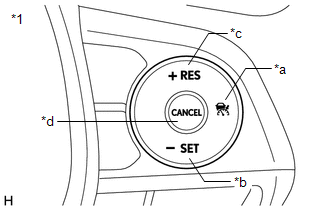
INPUT SIGNAL CHECK
(a) Connect the Techstream to the DLC3.
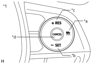
(b) Check the steering pad switch assembly using the Data List function of the Techstream (cruise control main switch, -SET switch, +RES switch and CANCEL switch).
Click here 
|
*1 | Steering Pad Switch Assembly |
|
*a | Cruise Control Main Switch |
|
*b | -SET Switch |
|
*c | +RES Switch |
|
*d | CANCEL Switch |
INSPECT CRUISE CONTROL MAIN SWITCH
(a) Turn the power switch on (IG).
(b) Turn the dynamic radar cruise control system on using the cruise control main switch.

|
*1 | Steering Pad Switch Assembly |
|
*a | Cruise Control Main Switch |
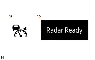
(c) Check that the cruise control indicator (vehicle-to-vehicle distance control mode) in the combination meter assembly illuminates and "Radar Ready" is displayed on the multi-information display.
|
*a | Cruise Control Indicator (Vehicle-to-vehicle Distance Control Mode) |
|
*b | Multi-information Display |
(d) Turn the dynamic radar cruise control system off using the cruise control main switch. Check that the cruise control indicator (vehicle-to-vehicle distance control mode) in the combination meter assembly and "Radar Ready" on the multi-information display turn off.
(e) Turn the power switch off with the cruise control indicator (vehicle-to-vehicle distance control mode) in the combination meter assembly illuminated and "Radar Ready" on the multi-information display displayed. Turn the power switch back on (IG) and check that the cruise control indicator (vehicle-to-vehicle distance control mode) in the combination meter assembly and "Radar Ready" on the multi-information display are turned off.
INSPECT MODE SELECT
(a) Turn the power switch on (IG).
(b) Push and hold the cruise control main switch for 1.5 seconds or more with the dynamic radar cruise control system off to change to constant speed control mode.
|
*1 | Steering Pad Switch Assembly |
|
*a | Cruise Control Main Switch |
NOTICE:
Do not push any other switches before pushing the cruise control main switch. If any other switches are pushed, turn the dynamic radar cruise control system off and repeat the above procedure.
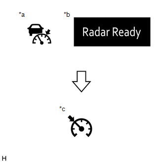
(c) Check that the cruise control indicator (vehicle-to-vehicle distance control mode) in the combination meter assembly and "Radar Ready" on the multi-information display turn off and the cruise control indicator (constant speed control mode) illuminates.
|
*a | Cruise Control Indicator (Vehicle-to-vehicle Distance Control Mode) |
|
*b | Multi-information Display |
|
*c | Cruise Control Indicator (Constant Speed Control Mode) |
HINT:
If a malfunction is detected, turn the power switch off and repeat the procedure above.
INSPECT VEHICLE-TO-VEHICLE DISTANCE CONTROL SWITCH
(a) Turn the power switch on (IG).
(b) Turn the dynamic radar cruise control system on using the cruise control main switch.
|
*1 | Steering Pad Switch Assembly |
|
*a | Cruise Control Main Switch |
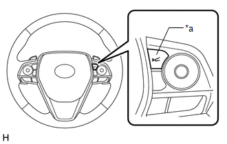
(c) Press the vehicle-to-vehicle distance control switch.
|
*a | Vehicle-to-vehicle Distance Control Switch |
(d) Check that the indicator of the vehicle-to-vehicle distance, which is shown on the multi-information display in the combination meter assembly changes from long to middle to short in that order.
HINT:
Long is automatically selected each time the power switch is turned on (IG).
DESCRIPTION
When the brakes are applied by the dynamic radar cruise control system, the skid control ECU (brake booster with master cylinder assembly) operates the stop light switch assembly (stop light control relay) to illuminate the stop lights.
If the hybrid vehicle control ECU receives a stop light control relay malfunction signal from the skid control ECU (brake booster with master cylinder assembly), DTC P057113 is stored.
|
DTC No. | Detection Item |
DTC Detection Condition | Trouble Area |
MIL |
|---|---|---|---|---|
| P057113 |
Brake Switch "A" Circuit Open |
While the vehicle speed is 5 km/h (3 mph) or more and the dynamic radar cruise control system is operating, the hybrid vehicle control ECU detects the stop light control relay malfunction signal from the skid control ECU (brake booster with master cylinder assembly) for approximately 0.2 seconds or more. |
Pre-collision system | Does not come on |
CAUTION / NOTICE / HINT
HINT:
When DTC P057113 is stored by the dynamic radar cruise control system, DTC C1A4B is stored by the pre-collision system. Therefore, if DTC P057113 is stored, inspect the pre-collision system first.
PROCEDURE
| 1. |
GO TO PRE-COLLISION SYSTEM |
Click here

| NEXT |  |
END |
DESCRIPTION
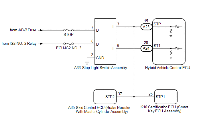
When the brake pedal is depressed, the stop light switch assembly sends a signal to the hybrid vehicle control ECU. When the hybrid vehicle control ECU receives this signal, it cancels the dynamic radar cruise control. The fail-safe function operates to enable normal driving even if there is a malfunction in the stop light signal circuit. The cancellation condition occurs when voltage is applied to the terminal STP. When the brake is applied, voltage is normally applied to the terminal STP of the hybrid vehicle control ECU through the STOP fuse and the stop light switch assembly, and the hybrid vehicle control ECU turns the dynamic radar cruise control system off.
|
DTC No. | Detection Item |
DTC Detection Condition | Trouble Area |
MIL |
|---|---|---|---|---|
| P057162 |
Brake Switch "A" Signal Compare Failure |
While the power switch is on (IG) and the dynamic radar cruise control system is operating, voltage of the STP terminal and that of the ST1- terminal of the hybrid vehicle control ECU are less than 1 V for approximately 0.5 seconds or more. |
| Does not come on |
WIRING DIAGRAM
CAUTION / NOTICE / HINT
NOTICE:
Click here 
PROCEDURE
|
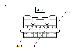
1. | CHECK HARNESS AND CONNECTOR (STOP LIGHT SWITCH ASSEMBLY - BATTERY AND BODY GROUND) |
| (a) Disconnect the A33 stop light switch assembly connector. |
|
(b) Measure the resistance according to the value(s) in the table below.
Standard Resistance:
|
Tester Connection | Condition |
Specified Condition |
|---|---|---|
|
A33-2 (GND) - Body ground |
Always | Below 1 Ω |
(c) Measure the voltage according to the value(s) in the table below.
Standard Voltage:
|
Tester Connection | Condition |
Specified Condition |
|---|---|---|
|
A33-7 (B) - Body ground |
Always | 11 to 14 V |
|
A33-6 (B) - Body ground |
Power switch on (IG) |
11 to 14 V |
|
A33-6 (B) - Body ground |
Power switch off | Below 1 V |
(d) Connect the A33 stop light switch assembly connector.
| NG |  | REPAIR OR REPLACE HARNESS OR CONNECTOR |
|
| 2. |
INSPECT STOP LIGHT SWITCH ASSEMBLY |
(a) Inspect the stop light switch assembly.
Click here
| NG | | REPLACE STOP LIGHT SWITCH ASSEMBLY |
|
| 3. |
CHECK HARNESS AND CONNECTOR (HYBRID VEHICLE CONTROL ECU - STOP LIGHT SWITCH ASSEMBLY) |
(a) Disconnect the A23 and A24 hybrid vehicle control ECU connectors.
(b) Disconnect the A33 stop light switch assembly connector.
(c) Disconnect the A35 skid control ECU (brake booster with master cylinder assembly) connector.
(d) Disconnect the K10 certification ECU (smart key ECU assembly) connector.
(e) Measure the resistance according to the value(s) in the table below.
Standard Resistance:
|
Tester Connection | Condition |
Specified Condition |
|---|---|---|
|
A24-28 (ST1-) - A33-5 (L) |
Always | Below 1 Ω |
|
A23-15 (STP) - A33-3 (L) |
Always | Below 1 Ω |
|
A24-28 (ST1-) or A33-5 (L) - Body ground |
Always | 10 kΩ or higher |
|
A23-15 (STP) or A33-3 (L) - Body ground |
Always | 10 kΩ or higher |
(f) Connect the K10 certification ECU (smart key ECU assembly) connector.
(g) Connect the A35 skid control ECU (brake booster with master cylinder assembly) connector.
(h) Connect the A33 stop light switch assembly connector.
(i) Connect the A23 and A24 hybrid vehicle control ECU connectors.
| OK | | REPLACE HYBRID VEHICLE CONTROL ECU |
| NG | | REPAIR OR REPLACE HARNESS OR CONNECTOR |
DESCRIPTION
This DTC is stored when there is a malfunction in the hybrid vehicle control ECU.
|
DTC No. | Detection Item |
DTC Detection Condition | Trouble Area |
MIL |
|---|---|---|---|---|
| P057504 |
Cruise Control System Internal Failure |
While the dynamic radar cruise control system is operating, the dynamic radar cruise control system control of vehicle speed is not canceled and approximately 0.4 seconds have elapsed since cruise cancel signal (STP signal) is received by the hybrid vehicle control ECU. |
Hybrid vehicle control ECU |
Does not come on |
|
P057549 | Cruise Control Internal Electronic Failure |
When the power switch is on (IG), STP signals received by the hybrid vehicle control ECU supervisory CPU and that received by the control ECU do not match for approximately 0.2 seconds or more. |
Hybrid vehicle control ECU |
Does not come on |
CAUTION / NOTICE / HINT
NOTICE:
Before replacing the hybrid vehicle control ECU, refer to Registration.
Click here 
PROCEDURE
| 1. |
CHECK FOR DTCs |
(a) Clear the DTCs.
Powertrain > Radar Cruise1 > Clear DTCs(b) Make sure that the DTC detection conditions are met.
HINT:
If the detection conditions are not met, the system cannot detect the malfunction.
(c) Check for DTCs.
Powertrain > Radar Cruise1 > Trouble Codes|
Result | Proceed to |
|---|---|
|
DTC P057504 and P057549 are not output. |
A |
| DTC P057504 or P057549 is output. |
B |
| A |
 | USE SIMULATION METHOD TO CHECK |
| B |
| REPLACE HYBRID VEHICLE CONTROL ECU |
DESCRIPTION
This DTC is stored when a malfunction is detected in the electronically controlled brake system. Check the electronically controlled brake system when DTC P157800 is stored.
|
DTC No. | Detection Item |
DTC Detection Condition | Trouble Area |
MIL |
|---|---|---|---|---|
| P157800 |
Brake System | While the vehicle speed is 5 km/h (3 mph) or more and the dynamic radar cruise control system is operating, a malfunction in the electronically controlled brake system is detected for 0.2 seconds or more. |
Electronically controlled brake system |
Does not come on |
PROCEDURE
| 1. |
GO TO ELECTRONICALLY CONTROLLED BRAKE SYSTEM |
HINT:
If DTC P157800 is output by the dynamic radar cruise control system, perform troubleshooting for the electronically controlled brake system.
Click here

| NEXT |  |
END |
DESCRIPTION
The hybrid vehicle control ECU continuously monitors its main and sub CPUs. This self-check ensures that the hybrid vehicle control ECU is functioning properly. If outputs from the CPUs are different and deviate from the standard, the hybrid vehicle control ECU will illuminate the MIL and store the DTC.
|
DTC No. | Detection Item |
DTC Detection Condition | Trouble Area |
MIL |
|---|---|---|---|---|
| P160700 |
Cruise Control Input Processor |
When prohibited by the sub-CPU, the dynamic radar cruise control system operates for 0.3 seconds or more. |
Hybrid vehicle control ECU |
Comes on |
MONITOR DESCRIPTION
The hybrid vehicle control ECU continuously monitors its main and sub CPUs. This self-check ensures that the hybrid vehicle control ECU is functioning properly. If outputs from the CPUs are different and deviate from the standard, illuminate the MIL and store the DTC immediately.
MONITOR STRATEGY
|
Related DTCs | P1607: Hybrid control module performance |
|
Required Sensors/Components (Main) | Hybrid vehicle control ECU |
|
Required Sensors/Components (Related) | Cruise control |
|
Frequency of Operation | Continuous |
|
Duration | 0.3 seconds |
| MIL Operation |
Immediate |
| Sequence of Operation |
None |
TYPICAL ENABLING CONDITIONS
|
Monitor runs whenever the following DTCs are not stored |
None |
| All of the following conditions are met |
- |
| Cruise control |
Forbiddance |
| DMA communication error |
Not detected |
TYPICAL MALFUNCTION THRESHOLDS
|
Cruise control | Operating |
CONFIRMATION DRIVING PATTERN
HINT:
When clearing the permanent DTCs, refer to the "CLEAR PERMANENT DTC" procedure.
Click here 
HINT:
[*1] : Normal judgment procedure.
The normal judgment procedure is used to complete DTC judgment and also used when clearing permanent DTCs.
HINT:
Click here
HINT:
CAUTION / NOTICE / HINT
NOTICE:
Before replacing the hybrid vehicle control ECU, refer to Registration.
Click here
HINT:
The hybrid vehicle control ECU receives signals from each sensor to control all functions of the dynamic radar cruise control system. When a DTC is detected, the fail-safe function remains on until the power switch is turned off.
PROCEDURE
| 1. |
CHECK FOR DTCs |
(a) Clear the DTCs.
Powertrain > Radar Cruise1 > Clear DTCs(b) Make sure that the DTC detection conditions are met.
HINT:
If the detection conditions are not met, the system cannot detect the malfunction.
(c) Check for DTCs.
Powertrain > Radar Cruise1 > Trouble Codes|
Result | Proceed to |
|---|---|
|
DTC P160700 is not output |
A |
| DTC P160700 is output |
B |
| A |
 | USE SIMULATION METHOD TO CHECK |
| B |
| REPLACE HYBRID VEHICLE CONTROL ECU |
DESCRIPTION
The skid control ECU (brake booster with master cylinder assembly) sends signals such as cruise control cancel signals and brake demand response signals to the hybrid vehicle control ECU when the dynamic radar cruise control system is operating.
|
DTC No. | Detection Item |
DTC Detection Condition | Trouble Area |
MIL |
|---|---|---|---|---|
| P163081 |
Communication Error from VSC to ECM Invalid Serial Data Received |
While the vehicle speed is 5 km/h (3 mph) or more and the dynamic radar cruise control system is operating, communication data from the skid control ECU (brake booster with master cylinder assembly) is logically inconsistent for approximately 0.5 seconds or more. |
| Does not come on |
CAUTION / NOTICE / HINT
NOTICE:
Click here 
Click here
Click here
PROCEDURE
|
1. | CHECK CAN COMMUNICATION SYSTEM |
(a) Using the Techstream, check if the CAN communication system is functioning normally.
Click here
|
Result | Proceed to |
|---|---|
|
CAN communication system DTCs are not output |
OK |
| CAN communication system DTCs are output |
NG |
| NG |  | GO TO CAN COMMUNICATION SYSTEM |
|
| 2. |
CHECK FOR DTCs |
(a) Clear the DTCs.
Powertrain > Radar Cruise1 > Clear DTCs(b) Make sure that the DTC detection conditions are met.
HINT:
If the detection conditions are not met, the system cannot detect the malfunction.
(c) Check for DTCs.
Powertrain > Radar Cruise1 > Trouble Codes|
Result | Proceed to |
|---|---|
|
DTC P163081 is not output |
A |
| DTC P163081 is output |
B |
| A |
| USE SIMULATION METHOD TO CHECK |
|
| 3. |
REPLACE BRAKE BOOSTER WITH MASTER CYLINDER ASSEMBLY |
(a) Replace the brake booster with master cylinder assembly.
Click here
|
| 4. |
CHECK FOR DTCs |
(a) Clear the DTCs.
Powertrain > Radar Cruise1 > Clear DTCs(b) Make sure that the DTC detection conditions are met.
HINT:
If the detection conditions are not met, the system cannot detect the malfunction.
(c) Check for DTCs.
Powertrain > Radar Cruise1 > Trouble Codes|
Result | Proceed to |
|---|---|
|
DTC P163081 is not output |
A |
| DTC P163081 is output |
B |
| A |
| END |
| B |
| REPLACE HYBRID VEHICLE CONTROL ECU |
DESCRIPTION
The hybrid vehicle control ECU sends signals such as dynamic radar cruise control operation signals, brake operation demand signals and buzzer operation demand signals to the skid control ECU (brake booster with master cylinder assembly) when the dynamic radar cruise control is operating. Therefore, if the skid control ECU (brake booster with master cylinder assembly) detects a communication error with the hybrid vehicle control ECU, it sends a malfunction signal back to the hybrid vehicle control ECU.
|
DTC No. | Detection Item |
DTC Detection Condition | Trouble Area |
MIL |
|---|---|---|---|---|
| P163181 |
Communication Error from ECM to VSC Invalid Serial Data Received |
While the vehicle speed is 5 km/h (3 mph) or more and the dynamic radar cruise control system is operating, the hybrid vehicle control ECU continuously receives a logic error signal from the skid control ECU (brake booster with master cylinder assembly) for approximately 1 second or more. |
| Does not come on |
CAUTION / NOTICE / HINT
NOTICE:
Click here 
Click here
Click here
PROCEDURE
|
1. | CHECK CAN COMMUNICATION SYSTEM |
(a) Using the Techstream, check if the CAN communication system is functioning normally.
Click here
|
Result | Proceed to |
|---|---|
|
CAN communication system DTCs are not output |
OK |
| CAN communication system DTCs are output |
NG |
| NG |  | GO TO CAN COMMUNICATION SYSTEM |
|
| 2. |
CHECK FOR DTCs |
(a) Clear the DTCs.
Powertrain > Radar Cruise1 > Clear DTCs(b) Make sure that the DTC detection conditions are met.
HINT:
If the detection conditions are not met, the system cannot detect the malfunction.
(c) Check for DTCs.
Powertrain > Radar Cruise1 > Trouble Codes|
Result | Proceed to |
|---|---|
|
DTC P163181 is not output |
A |
| DTC P163181 is output |
B |
| A |
| USE SIMULATION METHOD TO CHECK |
|
| 3. |
REPLACE HYBRID VEHICLE CONTROL ECU |
(a) Replace the hybrid vehicle control ECU.
Click here
|
| 4. |
CHECK FOR DTCs |
(a) Clear the DTCs.
Powertrain > Radar Cruise1 > Clear DTCs(b) Make sure that the DTC detection conditions are met.
HINT:
If the detection conditions are not met, the system cannot detect the malfunction.
(c) Check for DTCs.
Powertrain > Radar Cruise1 > Trouble Codes|
Result | Proceed to |
|---|---|
|
DTC P163181 is not output |
A |
| DTC P163181 is output |
B |
| A |
| END |
| B |
| REPLACE BRAKE BOOSTER WITH MASTER CYLINDER ASSEMBLY |
PARTS LOCATION
ILLUSTRATION
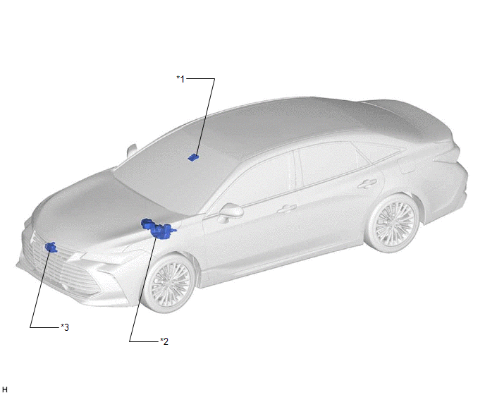
|
*1 | FORWARD RECOGNITION CAMERA |
*2 | BRAKE BOOSTER WITH MASTER CYLINDER ASSEMBLY - SKID CONTROL ECU |
|
*3 | MILLIMETER WAVE RADAR SENSOR ASSEMBLY |
- | - |
ILLUSTRATION
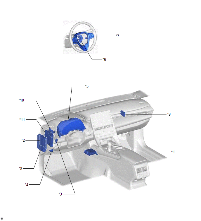
|
*1 | AIRBAG SENSOR ASSEMBLY - YAW RATE AND ACCELERATION SENSOR |
*2 | MAIN BODY ECU (MULTIPLEX NETWORK BODY ECU) |
|
*3 | STOP LIGHT SWITCH ASSEMBLY |
*4 | DLC3 |
|
*5 | COMBINATION METER ASSEMBLY - Multi-information Display - Cruise Control Indicator - Cruise SET Indicator - Warning Buzzer - Master Warning Light |
*6 | SPIRAL CABLE WITH SENSOR SUB-ASSEMBLY - SPIRAL CABLE SUB-ASSEMBLY - STEERING SENSOR |
|
*7 | STEERING PAD SWITCH ASSEMBLY (CRUISE CONTROL SWITCH) - VEHICLE-TO-VEHICLE DISTANCE CONTROL SWITCH - CRUISE CONTROL MAIN SWITCH - -SET SWITCH - +RES SWITCH - CANCEL SWITCH |
*8 | INSTRUMENT PANEL JUNCTION BLOCK ASSEMBLY - STOP FUSE - ECU-IG1 NO. 4 FUSE - ECU-IG2 NO. 3 FUSE |
|
*9 | CENTRAL GATEWAY ECU (NETWORK GATEWAY ECU) |
*10 | DRIVING SUPPORT ECU ASSEMBLY |
|
*11 | HYBRID VEHICLE CONTROL ECU |
- | - |
PRECAUTION
PRECAUTION FOR DISCONNECTING CABLE FROM NEGATIVE AUXILIARY BATTERY TERMINAL
NOTICE:
When disconnecting the cable from the negative (-) auxiliary battery terminal, initialize the following system(s) after the cable is reconnected:
|
System | See Procedure |
|---|---|
|
Lane Departure Alert System (w/ Steering Control) |
|
|
Pre-collision System | |
|
Intelligent Clearance Sonar System | |
|
Lighting System (for HV Model with Cornering Light) | |
|
Parking Assist Monitor System | |
|
Panoramic View Monitor System |
HANDLING PRECAUTION FOR DYNAMIC RADAR CRUISE CONTROL SYSTEM
Keep in mind the following points when servicing vehicles equipped with the dynamic radar cruise control system.
(a) The dynamic radar cruise control system is designed to be used when driving on highways and freeways. The system may not operate correctly when driving on roads used by pedestrians and bicycles, and may result in an accident.
(b) Do not overly rely on the dynamic radar cruise control system.
(c) The millimeter wave radar sensor assembly dirt detection function.
HINT:
The preceding conditions may result in the vehicle being unable to maintain an appropriate distance with the preceding vehicle.
(d) Keep the sensor face and the front and back surfaces of the front emblem clean.
(e) The dynamic radar cruise control system does not operate or give a vehicle approach warning for vehicles which are stopped or driving at significantly slower speeds.
HINT:
This includes vehicles stopped at a tollgate or in traffic, or a preceding vehicle driving at significantly slower speeds.
(f) When following another vehicle with vehicle-to-vehicle distance control mode controlling vehicle speed, the vehicle will not accelerate if the +RES switch is pushed, as the speed is controlled in accordance with the speed of the preceding vehicle.
NOTICE:
If the set vehicle speed is increased by pushing the +RES switch, the vehicle will accelerate to the newly set speed when the preceding vehicle moves out of the lane.
HINT:
The set vehicle speed can be confirmed on the multi-information display.
(g) The actual vehicle-to-vehicle distance may be shorter than the set vehicle-to-vehicle distance when driving on a downhill road.
(h) When a system malfunction is detected, the master warning light illuminates, a warning message is displayed on the multi-information display in the combination meter assembly and the buzzer sounds.
(i) Keep the windshield glass clean.
(j) Do not apply excessive force to the forward recognition camera or subject it to a strong impact.
(k) Do not disassemble the forward recognition camera.
(l) Do not attach a sticker to the windshield glass in the area in front of the forward recognition camera.
(m) If the heater is used with FOOT mode selected, the upper area of the windshield glass may fog up, affecting the operation of the forward recognition camera.
HINT:
If the windshield glass fogs up, clear it using the front defroster.
(n) Do not damage the forward recognition camera lens or allow it to become dirty.
HINT:
(o) Do not place any objects on top of the instrument panel.
HINT:
If an object is reflecting off of the windshield glass, the performance of the forward recognition camera may decrease.
(p) The vehicle approach warning buzzer does not sound when constant speed control mode is controlling vehicle speed.
(q) As the controls performed by constant speed control mode and vehicle-to-vehicle distance control mode are different, always confirm which mode is selected before operating the dynamic radar cruise control system.
(r) Take the following precautions concerning the dynamic radar cruise control system.
(1) Turn the cruise control system off using the cruise control main switch when not using the cruise control system.
(2) Be careful as the vehicle speed may increase beyond the set vehicle speed when driving downhill even when the cruise control system is controlling vehicle speed.
(3) If the +RES switch is operated while the cruise control system is controlling vehicle speed or after control of vehicle speed by the cruise control system is canceled, the vehicle may accelerate.
(4) If the cruise control indicator turns off and a warning message is displayed when the cruise control system is controlling vehicle speed, turn the cruise control system off then on using the cruise control main switch and set the cruise control system vehicle set speed again. If the cruise control system does not turn on or stops functioning immediately after being set, there may be a malfunction in the cruise control system.
(5) Do not use the dynamic radar cruise control system where the road conditions are as follows:
(s) Do not use the dynamic radar cruise control system while towing.
PRECAUTIONS WHEN REPLACING DRIVING SUPPORT ECU ASSEMBLY
When replacing the driving support ECU assembly, always replace it with a new one. If a driving support ECU assembly which was installed to another vehicle is used, the information stored in the driving support ECU assembly will not match the information from the vehicle. As a result, a DTC may be stored.
PRECAUTION WHEN REPLACING HYBRID VEHICLE CONTROL ECU
Before replacing the hybrid vehicle control ECU, refer to Registration.
Click here 
HANDLING PRECAUTIONS FOR CAN COMMUNICATION SYSTEM
First check the CAN communication system by following How to Proceed with Troubleshooting. After checking that there are no malfunctions in the CAN communication system, proceed with troubleshooting.
Click here
HANDLING PRECAUTIONS FOR FORWARD RECOGNITION CAMERA
Click here
PRECAUTIONS WHEN REPLACING MILLIMETER WAVE RADAR SENSOR ASSEMBLY
Click here
PRECAUTION WHEN REPLACING SKID CONTROL ECU (BRAKE BOOSTER WITH MASTER CYLINDER ASSEMBLY)
After the skid control ECU (brake booster with master cylinder assembly) is replaced, perform the yaw rate sensor and G sensor zero point calibration and store the system information.
Click here
PROBLEM SYMPTOMS TABLE
NOTICE:
Click here 
Click here
Click here
HINT:
|
Symptom | Suspected Area |
Link |
|---|---|---|
|
The dynamic radar cruise control system cannot be turned on using the cruise control main switch |
CAN communication system |
|
|
Steering pad switch circuit |
| |
|
Cruise main indicator light circuit |
| |
|
Combination meter assembly |
| |
|
Driving support ECU assembly |
| |
|
Hybrid vehicle control ECU |
| |
|
The dynamic radar cruise control mode cannot be changed between vehicle-to-vehicle distance control mode and constant speed control mode |
CAN communication system |
|
|
Steering pad switch circuit |
| |
|
Combination meter assembly |
| |
|
Hybrid vehicle control ECU |
| |
|
The vehicle-to-vehicle distance cannot be changed |
CAN communication system |
|
|
Distance control switch circuit |
| |
|
Combination meter assembly |
| |
|
Driving support ECU assembly |
| |
|
Vehicle speed setting cannot be performed (in constant speed control mode) |
Fail-safe chart |
|
|
CAN communication system |
| |
|
Steering pad switch circuit |
| |
|
Stop light switch circuit |
| |
|
Hybrid control system |
| |
|
Electronically controlled brake system |
| |
|
Driving support ECU assembly |
| |
|
Hybrid vehicle control ECU |
| |
|
Vehicle speed setting cannot be performed (in vehicle-to-vehicle distance control mode) |
Millimeter wave radar sensor assembly front radar incorrect axis gap (vertical) history*1 |
|
|
Fail-safe chart |
| |
|
Forward recognition camera is temporarily unavailable |
| |
|
Millimeter wave radar sensor assembly is dirty |
| |
|
Millimeter wave radar sensor assembly beam axis not adjusted |
| |
|
CAN communication system |
| |
|
Steering pad switch circuit |
| |
|
Hybrid control system |
| |
|
Millimeter wave radar sensor assembly |
| |
|
Forward recognition camera |
| |
|
Electronically controlled brake system |
| |
|
Combination meter assembly |
| |
|
Driving support ECU assembly |
| |
|
Hybrid vehicle control ECU |
| |
|
Control of vehicle speed by the dynamic radar cruise control system is canceled (in constant speed control mode) |
Fail-safe chart |
|
|
CAN communication system |
| |
|
Steering pad switch circuit |
| |
|
Stop light switch circuit |
| |
|
Hybrid control system |
| |
|
Electronically controlled brake system |
| |
|
Driving support ECU assembly |
| |
|
Hybrid vehicle control ECU |
| |
|
Control of vehicle speed by the dynamic radar cruise control system is canceled (in vehicle-to-vehicle distance control mode) |
Fail-safe chart |
|
|
Forward recognition camera is temporarily unavailable |
| |
|
Millimeter wave radar sensor assembly is dirty |
| |
|
Millimeter wave radar sensor assembly beam axis not adjusted |
| |
|
CAN communication system |
| |
|
Steering pad switch circuit |
| |
|
Hybrid control system |
| |
|
Millimeter wave radar sensor assembly |
| |
|
Forward recognition camera |
| |
|
Electronically controlled brake system |
| |
|
Combination meter assembly |
| |
|
Driving support ECU assembly |
| |
|
Hybrid vehicle control ECU |
| |
|
Hunting/vehicle speed is not constant (in constant speed control mode) |
CAN communication system |
|
|
Electronically controlled brake system |
| |
|
Hybrid vehicle control ECU |
| |
|
Hunting/vehicle speed is not constant (in vehicle-to-vehicle distance control mode) |
Millimeter wave radar sensor assembly is dirty |
|
|
Millimeter wave radar sensor assembly beam axis not adjusted |
| |
|
CAN communication system |
| |
|
Electronically controlled brake system |
| |
|
Driving support ECU assembly |
| |
|
Hybrid vehicle control ECU |
| |
|
Vehicle speed control by the dynamic radar cruise control system is not canceled when the CANCEL switch is pushed |
Steering pad switch circuit |
|
|
Hybrid vehicle control ECU |
| |
|
Moving the shift lever does not cancel control of vehicle speed by the dynamic radar cruise control system |
Shift lever position sensor |
|
|
Shift lock control unit assembly |
| |
|
Hybrid control system |
| |
|
Hybrid vehicle control ECU |
| |
|
Vehicle speed control by the dynamic radar cruise control system is not canceled when a shift paddle switch is operated*2 |
Hybrid control system |
|
|
Shift paddle switch circuit |
| |
|
Hybrid vehicle control ECU |
| |
|
Depressing the brake pedal does not cancel control of vehicle speed by the dynamic radar cruise control system |
Stop light switch circuit |
|
|
Hybrid vehicle control ECU |
| |
|
Control cannot be canceled while the vehicle is stopped |
CAN communication system |
|
|
Electronically controlled brake system |
| |
|
Electric parking brake system |
| |
|
Front door courtesy switch circuit |
| |
|
Seat belt warning system |
| |
|
Hybrid vehicle control ECU |
| |
|
Control cannot be canceled by operating the parking brake |
CAN communication system |
|
|
Electronically controlled brake system |
| |
|
Electric parking brake system |
| |
|
Brake actuator assembly |
| |
|
Driving support ECU assembly |
| |
|
Hybrid vehicle control ECU |
| |
|
Even though the millimeter wave radar sensor assembly is not dirty, the warning message "Clean Sensor" is displayed |
Millimeter wave radar sensor assembly |
|
|
The vehicle approach warning buzzer does not sound |
Combination meter assembly |
|
|
Check millimeter wave radar sensor assembly installation position |
| |
|
Check installation of forward recognition camera |
| |
|
Forward recognition camera |
| |
|
Millimeter wave radar sensor assembly |
| |
|
Driving support ECU assembly |
| |
|
Even though the vehicle approach warning buzzer is sounding, brake control is not performed to decelerate the vehicle |
Electronically controlled brake system |
|
|
CAN communication system |
| |
|
Driving support ECU assembly |
| |
|
Hybrid vehicle control ECU |
| |
|
Even though the SET function is operating, the cruise SET indicator does not illuminate |
CAN communication system |
|
|
Cruise SET indicator light circuit |
| |
|
Combination meter assembly |
| |
|
Hybrid vehicle control ECU |
| |
|
The cruise control indicator remains illuminated |
CAN communication system |
|
|
Cruise main indicator light circuit |
| |
|
Combination meter assembly |
| |
|
Hybrid vehicle control ECU |
| |
|
Indicators are not displayed on the multi-information display in the combination meter assembly |
CAN communication system |
|
|
Combination meter assembly |
| |
|
Hybrid vehicle control ECU |
| |
|
A buzzer does not sound when control of vehicle speed by the dynamic radar cruise control is canceled |
CAN communication system |
|
|
Combination meter assembly |
| |
|
Hybrid vehicle control ECU |
|
*1: When the "Radar Cruise Control Unavailable" message is displayed and "Front Radar Incorrect Axis Gap (Vertical) History: ON" is output, the millimeter wave radar sensor assembly may be automatically performing beam axis calibration. In this case, the display is turned off due to beam axis adjustment being performed. Automatic calibration is complete when the "Radar Cruise Control Unavailable" message turns off.
*2: w/ Shift Paddle Switch
ROAD TEST
HINT:
PROBLEM SYMPTOM CONFIRMATION (VEHICLE-TO-VEHICLE DISTANCE CONTROL MODE)
(a) Inspect the SET function.
(1) Turn the dynamic radar cruise control system on using the cruise control main switch.
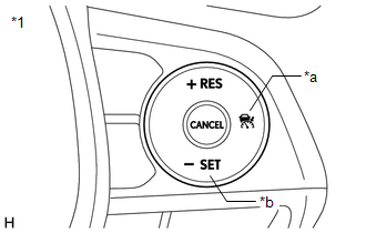
|
*1 | Steering Pad Switch Assembly |
|
*a | Cruise Control Main Switch |
|
*b | -SET Switch |
(2) Check that the cruise control indicator illuminates in the combination meter assembly.
(3) Drive at a speed between approximately 50 km/h (31 mph) and 180 km/h (112 mph).
(4) Push the -SET switch.
(5) Check that the cruise control indicator remains illuminated, the cruise SET indicator illuminates in the combination meter assembly and the set speed is displayed on the multi-information display.
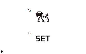
|
*a | Cruise Control Indicator (Vehicle-to-vehicle Distance Control Mode) |
|
*b | Cruise SET Indicator |
(6) After releasing the switch, check that the vehicle maintains the set speed.
(b) Inspect the + (ACCEL) function.
(1) Turn the dynamic radar cruise control system on using the cruise control main switch.
|
*1 | Steering Pad Switch Assembly |
|
*a | Cruise Control Main Switch |
|
*b | -SET Switch |
(2) Drive at a speed between approximately 50 km/h (31 mph) and 180 km/h (112 mph).
(3) Push the -SET switch.
(4) Push and hold the +RES switch and check that vehicle speed increases in 1 km/h or 1 mph*1 or 5 km/h or 5 mph*2 increments.
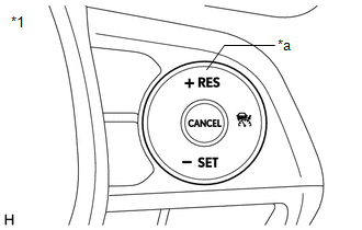
|
*1 | Steering Pad Switch Assembly |
|
*a | +RES Switch |
*1: for Speedometer with Imperial Units for Main Scale
*2: for Speedometer with Metric Units for Main Scale
(5) Push the +RES switch and then release it immediately. Check that vehicle speed increases by approximately 1 km/h or 1 mph (tap-up control).
(c) Inspect the - (COAST) function.
(1) Turn the dynamic radar cruise control system on using the cruise control main switch.
|
*1 | Steering Pad Switch Assembly |
|
*a | Cruise Control Main Switch |
|
*b | -SET Switch |
(2) Drive at a speed between approximately 50 km/h (31 mph) and 180 km/h (112 mph).
(3) Push the -SET switch.
(4) Push and hold the -SET switch and check that vehicle speed decreases in 1 km/h or 1 mph*1 or 5 km/h or 5 mph*2 increments.
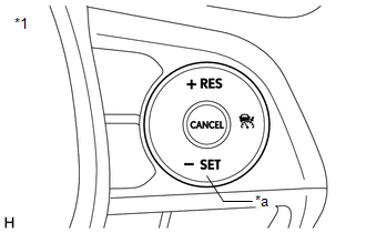
|
*1 | Steering Pad Switch Assembly |
|
*a | -SET Switch |
*1: for Speedometer with Imperial Units for Main Scale
*2: for Speedometer with Metric Units for Main Scale
(5) Push the -SET switch, and then release it immediately. Check that vehicle speed decreases by approximately 1 km/h or 1 mph (tap-down control).
(d) Inspect the CANCEL function.
(1) Turn the dynamic radar cruise control system on using the cruise control main switch.
|
*1 | Steering Pad Switch Assembly |
|
*a | Cruise Control Main Switch |
|
*b | -SET Switch |
(2) Drive at a speed between approximately 50 km/h (31 mph) and 180 km/h (112 mph).
(3) Push the -SET switch.
(4) When any of the following are performed, check that control of vehicle speed by the dynamic radar cruise control system is canceled and that the normal driving mode (no control of vehicle speed by the dynamic radar cruise control system) resumes.
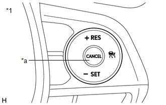
|
*1 | Steering Pad Switch Assembly |
|
*a | CANCEL Switch |
(e) Inspect the RES (RESUME) function.
(1) Turn the dynamic radar cruise control system on using the cruise control main switch.
|
*1 | Steering Pad Switch Assembly |
|
*a | Cruise Control Main Switch |
|
*b | -SET Switch |
(2) Drive at a speed between approximately 50 km/h (31 mph) and 180 km/h (112 mph).
(3) Push the -SET switch.
(4) Cancel control of vehicle speed by the dynamic radar cruise control system by performing any of the CANCEL functions (other than turning the dynamic radar cruise control system off using the cruise control main switch).
(5) Push the +RES switch while driving the vehicle at a speed of more than approximately 40 km/h (25 mph), and check that the vehicle resumes the speed set prior to cancellation and that the cruise SET indicator illuminates.
HINT:
The stored vehicle speed is retained even if the vehicle speed drops below approximately 40 km/h (25 mph). The previously stored vehicle speed can be resumed by pushing the +RES switch when the vehicle speed has returned to approximately 40 km/h (25 mph) or more.
|
*1 | Steering Pad Switch Assembly |
|
*a | +RES Switch |
PROBLEM SYMPTOM CONFIRMATION (CONSTANT SPEED CONTROL MODE)
(a) Inspect the SET function.
(1) Push and hold the switch of the cruise control main switch for 1.5 seconds or more with the dynamic radar cruise control system off to change to the constant speed control mode.
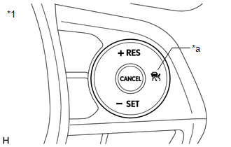
|
*1 | Steering Pad Switch Assembly |
|
*a | Cruise Control Main Switch |
(2) Check that the cruise control indicator (vehicle-to-vehicle distance control mode) turns off and the cruise control indicator (constant speed control mode) illuminates.
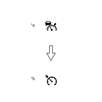
|
*a | Cruise Control Indicator (Vehicle-to-vehicle Distance Control Mode) |
|
*b | Cruise Control Indicator (Constant Speed Control Mode) |
(3) Drive at a speed between 40 km/h (25 mph) and 200 km/h (124 mph).
(4) Push the -SET switch.
|
*1 | Steering Pad Switch Assembly |
|
*a | -SET Switch |
(5) Check that the cruise SET indicator illuminates at this time.
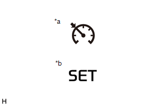
|
*a | Cruise Control Indicator |
|
*b | Cruise SET Indicator |
(6) After releasing the switch, check that the vehicle maintains the set speed.
(b) Inspect the + (ACCEL) function.
(1) Push and hold the switch of the cruise control main switch for 1.5 seconds or more with the dynamic radar cruise control system off to change to the constant speed control mode.
|
*1 | Steering Pad Switch Assembly |
|
*a | Cruise Control Main Switch |
|
*b | -SET Switch |
(2) Drive at a speed between 40 km/h (25 mph) and 200 km/h (124 mph).
(3) Push the -SET switch.
(4) Check that vehicle speed increases while the +RES switch is pushed, and that the vehicle maintains the newly set speed when the switch is released.
|
*1 | Steering Pad Switch Assembly |
|
*a | +RES Switch |
(5) Push the +RES switch and then release it immediately. Check that vehicle speed increases by approximately 1 km/h or 1 mph (tap-up control).
(c) Inspect the - (COAST) function.
(1) Push and hold the switch of the cruise control main switch for 1.5 seconds or more with the dynamic radar cruise control system off to change to the constant speed control mode.
|
*1 | Steering Pad Switch Assembly |
|
*a | Cruise Control Main Switch |
|
*b | -SET Switch |
(2) Drive at a speed between 40 km/h (25 mph) and 200 km/h (124 mph).
(3) Push the -SET switch.
(4) Check that vehicle speed decreases while the - SET switch is pushed, and the vehicle maintains the newly set speed when the switch is released.
|
*1 | Steering Pad Switch Assembly |
|
*a | -SET Switch |
(5) Push the -SET switch, and then release it immediately. Check that vehicle speed decreases by approximately 1 km/h or 1 mph (tap-down control).
(d) Inspect the CANCEL function.
(1) Push and hold the switch of the cruise control main switch for 1.5 seconds or more with the dynamic radar cruise control system off to change to the constant speed control mode.
|
*1 | Steering Pad Switch Assembly |
|
*a | Cruise Control Main Switch |
|
*b | -SET Switch |
(2) Drive at a speed between 40 km/h (25 mph) and 200 km/h (124 mph).
(3) Push the -SET switch.
(4) When any of the following are performed, check that cruise control system control of vehicle speed is canceled and that the normal driving mode (no control of vehicle speed by the cruise control system) resumes.
|
*1 | Steering Pad Switch Assembly |
|
*a | CANCEL Switch |
(e) Inspect the RES (RESUME) function.
(1) Push and hold the switch of the cruise control main switch for 1.5 seconds or more with the dynamic radar cruise control system off to change to the constant speed control mode.
|
*1 | Steering Pad Switch Assembly |
|
*a | Cruise Control Main Switch |
|
*b | -SET Switch |
(2) Drive at a speed between 40 km/h (25 mph) and 200 km/h (124 mph).
(3) Push the -SET switch.
(4) Cancel cruise control system control of vehicle speed by performing any of the above operations (other than turning the cruise control system off using the cruise control main switch).
(5) After pushing the +RES switch at a speed of more than 40 km/h (25 mph), check that the vehicle resumes the speed set prior to cancellation.
|
*1 | Steering Pad Switch Assembly |
|
*a | +RES Switch |
CHECK FULL-SPEED RANGE FOLLOWING FUNCTION
(a) Check the SET function.
(1) Turn the dynamic radar cruise control system on using the cruise control main switch.
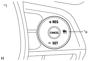
|
*1 | Steering Pad Switch Assembly |
|
*a | Cruise Control Main Switch |
(2) Drive at a speed between approximately 0 km/h (0 mph) and 180 km/h (112 mph).
(3) Check that there is a preceding vehicle that can be tracked.
HINT:
Tracking control may not track the preceding vehicle under the following conditions:
(4) Push the -SET switch.
|
*1 | Steering Pad Switch Assembly |
|
*a | -SET Switch |
(5) Check that tracking of the preceding vehicle begins with the set vehicle speed as the upper limit when the -SET switch is pressed.
(6) Check that the set vehicle speed is displayed on the multi-information display in the combination meter assembly.
(b) Check the deceleration function.
(1) When the preceding vehicle decelerates, check that the vehicle automatically decelerates while maintaining the set vehicle-to-vehicle distance.
(2) When the vehicle stops, check that "Waiting" is displayed on the multi-information display in the combination meter assembly.
HINT:
When "Waiting" is displayed on the multi-information display in the combination meter assembly, even if the brake pedal is depressed, tracking control is not canceled.
(c) Check the acceleration function.
(1) When the preceding vehicle starts off, check that "Operate Cruise Switch or Accelerator Pedal to Resume" is displayed on the multi-information display in the combination meter assembly.
(2) When the +RES switch is pushed or the accelerator pedal is depressed, check that tracking control resumes and begins tracking the preceding vehicle.
|
*1 | Steering Pad Switch Assembly |
|
*a | +RES Switch |
(d) Check the tracking control cancel function.
(1) When the vehicle speed is approximately 40 km/h (25 mph) or less and the preceding vehicle is no longer in front of the vehicle, check that "Radar Cruise Control Not Available No Preceding Vehicle" is displayed on the multi-information display in the combination meter assembly, the warning buzzer sounds 4 times and tracking control cancels.
HINT:
Tracking control also automatically cancels when the preceding vehicle moves out of the detection range due to a curve, etc., when the vehicle speed is 40 km/h (25 mph) or less.
DESCRIPTION
WIRING DIAGRAM
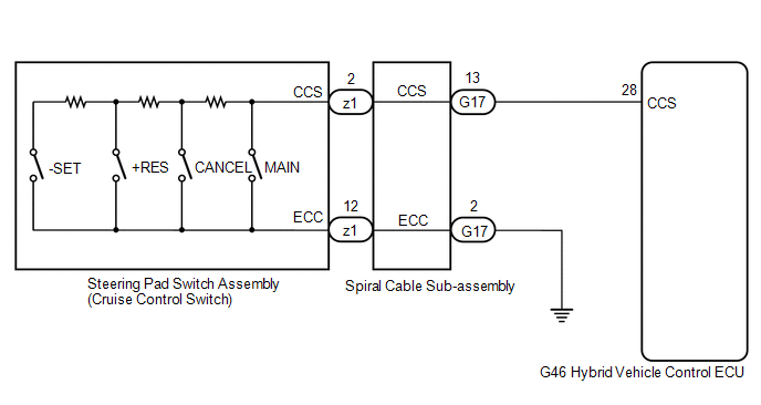
CAUTION / NOTICE / HINT
NOTICE:
Click here 
Click here
PROCEDURE
|
1. | READ VALUE USING TECHSTREAM |
| (a) Connect the Techstream to the DLC3. |
|
(b) Turn the power switch on (IG).
(c) Turn the Techstream on.
(d) Enter the following menus: Powertrain / Radar Cruise 1 / Data List.
(e) Read the Data List according to the display on the Techstream.
Powertrain > Radar Cruise1 > Data List|
Tester Display | Measurement Item |
Range | Normal Condition |
Diagnostic Note |
|---|---|---|---|---|
|
Cancel Switch | CANCEL switch status |
ON or OFF | ON: CANCEL switch pushed OFF: CANCEL switch not pushed |
- |
| -SET Switch |
-SET switch status | ON or OFF |
ON: -SET switch pushed OFF: -SET switch not pushed |
- |
| +RES Switch |
+RES switch status | ON or OFF |
ON: +RES switch pushed OFF: +RES switch not pushed |
- |
| Cruise Main Switch Operation Condition |
Cruise control main switch status |
ON or OFF | ON: Cruise control main switch pushed OFF: Cruise control main switch not pushed |
- |
|
Tester Display |
|---|
| Cancel Switch |
|
-SET Switch |
| +RES Switch |
|
Cruise Main Switch Operation Condition |
OK:
The value of each measurement item changes according to the operation of the steering pad switch assembly.
| OK |  | PROCEED TO NEXT SUSPECTED AREA SHOWN IN PROBLEM SYMPTOMS TABLE |
|
| 2. |
INSPECT STEERING PAD SWITCH ASSEMBLY |
(a) Remove the steering pad switch assembly.
Click here
(b) Inspect the steering pad switch assembly.
Click here
| NG | | REPLACE STEERING PAD SWITCH ASSEMBLY |
|
| 3. |
INSPECT SPIRAL CABLE SUB-ASSEMBLY |
(a) Remove the spiral cable sub-assembly.
Click here
(b) Inspect the spiral cable sub-assembly.
Click here
| NG | | REPLACE SPIRAL CABLE SUB-ASSEMBLY |
|
| 4. |
CHECK HARNESS AND CONNECTOR (SPIRAL CABLE SUB-ASSEMBLY - HYBRID VEHICLE CONTROL ECU AND BODY GROUND) |
(a) Disconnect the G17 spiral cable sub-assembly connector.
(b) Disconnect the G46 hybrid vehicle control ECU connector.
(c) Measure the resistance according to the value(s) in the table below.
Standard Resistance:
|
Tester Connection | Condition |
Specified Condition |
|---|---|---|
|
G17-13 (CCS) - G46-28 (CCS) |
Always | Below 1 Ω |
|
G17-2 (ECC) - Body ground |
Always | Below 1 Ω |
|
G17-13 (CCS) or G46-28 (CCS) - Body ground |
Always | 10 kΩ or higher |
(d) Connect the G46 hybrid vehicle control ECU connector.
(e) Connect the G17 spiral cable sub-assembly connector.
| OK | | REPLACE HYBRID VEHICLE CONTROL ECU |
| NG | | REPAIR OR REPLACE HARNESS OR CONNECTOR |
SYSTEM DIAGRAM
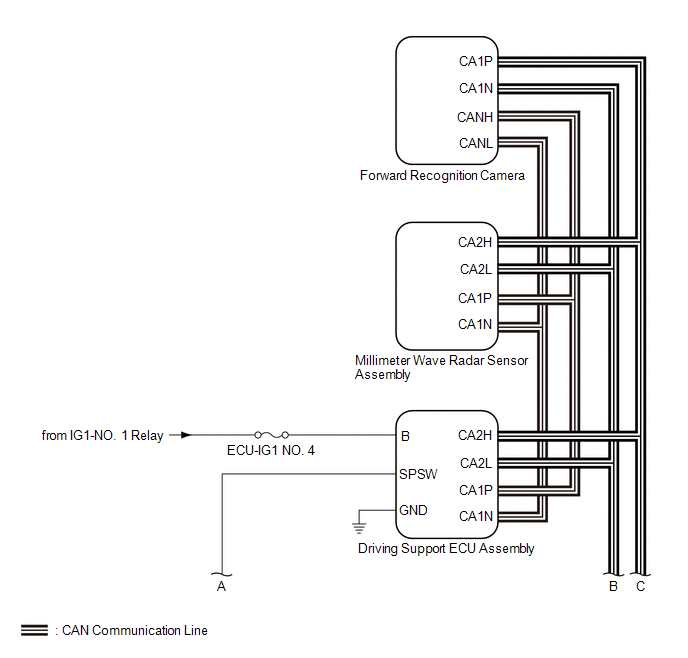
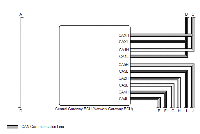
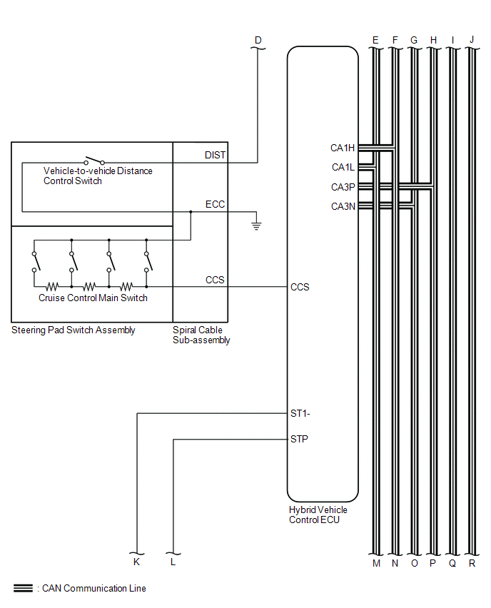
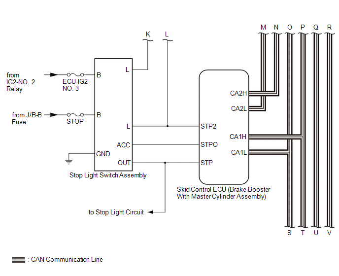
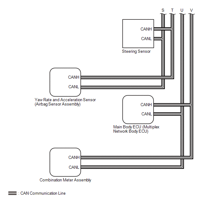 Communication Table
 |
Sender | Receiver |
Signal | Line |
|---|---|---|---|
|
Hybrid Vehicle Control ECU |
Driving Support ECU Assembly |
| CAN |
|
Skid Control ECU (Brake Booster With Master Cylinder Assembly) |
| CAN | |
|
Combination Meter Assembly |
| CAN | |
|
Forward Recognition Camera |
Cruise control operation signal |
CAN | |
|
Driving Support ECU Assembly |
Hybrid Vehicle Control ECU |
| CAN |
|
Combination Meter Assembly | Millimeter wave radar sensor assembly beam axis deviation signal |
CAN | |
|
Skid Control ECU (Brake Booster With Master Cylinder Assembly) |
Driving Support ECU Assembly |
| CAN |
|
Hybrid Vehicle Control ECU |
| CAN | |
|
Steering Sensor | Driving Support ECU Assembly |
| CAN |
|
Main Body ECU (Multiplex Network Body ECU) |
Driving Support ECU Assembly |
Destination information signal |
CAN |
| Yaw Rate and Acceleration Sensor (Airbag Sensor Assembly) |
Driving Support ECU Assembly |
| CAN |
TERMINALS OF ECU
CHECK DRIVING SUPPORT ECU ASSEMBLY

NOTICE:
Do not apply excessive force to the connector. If a force of 10 kg or more is applied, the connector may be broken.
(a) Measure the voltage and resistance according to the value(s) in the table below.
|
Terminal No. (Symbol) | Wiring Color |
Terminal Description | Condition |
Specified Condition |
|---|---|---|---|---|
|
G39-23 (SPSW) - G39-28 (GND) |
R - W-B | Steering pad switch assembly signal (distance control signal) |
Power switch on (IG), steering pad switch assembly (vehicle-to-vehicle distance control switch) off |
4.75 to 5.25 V |
|
Power switch on (IG), steering pad switch assembly (vehicle-to-vehicle distance control switch) on |
Below 1 V | |||
|
G39-28 (GND) - Body ground |
W-B - Body ground | Ground |
Always | Below 1 Ω |
|
G39-7 (B) - G39-28 (GND) |
B - W-B | Power source |
Power switch on (IG) |
11 to 14 V |
| Power switch off |
Below 1 V |
(b) Check for pulses according to the value(s) in the table below.
HINT:
If the waveform is not similar to that shown in the illustration, a malfunction of a CAN bus line, terminating resistor, or the driving support ECU assembly is suspected.
|
Terminal No. (Symbol) | Wiring Color |
Terminal Description | Condition |
Specified Condition |
|---|---|---|---|---|
|
G39-8 (CA1P) - G39-28 (GND) |
G - W-B | CAN communication signal |
Power switch on (IG) |
Pulse generation (See waveform 1) |
|
G39-9 (CA1N) - G39-28 (GND) |
W - W-B | Pulse generation (See waveform 2) | ||
|
G39-10 (CA2H) - G39-28 (GND) |
R - W-B | Pulse generation (See waveform 1) | ||
|
G39-11 (CA2L) - G39-28 (GND) |
W - W-B | Pulse generation (See waveform 2) |
(1) WAVEFORM 1
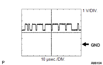
|
Item | Content |
|---|---|
|
Tester Connection |
|
| Tool Setting |
1 V/DIV., 10 μsec./DIV. |
|
Condition | Power switch on (IG) |
HINT:
The waveform varies depending on the CAN communication signal.
(2) WAVEFORM 2
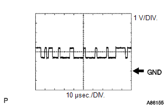
|
Item | Content |
|---|---|
|
Tester Connection |
|
| Tool Setting |
1 V/DIV., 10 μsec./DIV. |
|
Condition | Power switch on (IG) |
HINT:
The waveform varies depending on the CAN communication signal.
CHECK HYBRID VEHICLE CONTROL ECU
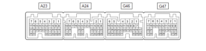
HINT:
The standard voltage, resistance and waveform between each pair of the hybrid vehicle control ECU terminals is shown in the table below. The appropriate conditions for checking each pair of the terminals is also indicated. The result of checks should be compared with the standard voltage, resistance and waveform for each pair of the terminals as displayed in the Specified Condition column. The illustration above can be used as a reference to identify the hybrid vehicle control ECU terminal locations.
|
Terminal No. (Symbols) | Wiring Color |
Terminal Description | Condition |
Specified Condition |
|---|---|---|---|---|
|
A23-15 (STP) - G46-6 (E1) |
LA-G - W-B | Stop light switch signal |
Brake pedal depressed |
11 to 14 V |
| Brake pedal released |
0 to 1.5 V | |||
|
G46-28 (CCS) - G46-6 (E1) |
GR - W-B | Steering pad switch circuit |
Cruise control switch not pushed |
1 MΩ or higher |
|
Cruise control main switch pushed |
Below 2.5 Ω | |||
|
CANCEL switch pushed |
228 to 252 Ω | |||
|
+RES switch pushed | 599 to 661 Ω | |||
|
-SET switch pushed | 1463 to 1617 Ω | |||
|
A24-28 (ST1-) - G46-6 (E1) |
LG - W-B | Stop light switch signal |
Power switch on (IG), brake pedal depressed |
0 to 1.5 V |
| Power switch on (IG), brake pedal released |
11 to 14 V |

CHECK MILLIMETER WAVE RADAR SENSOR ASSEMBLY
(a) Measure the voltage and resistance according to the value(s) in the table below.
|
Terminal No. (Symbol) | Wiring Color |
Terminal Description | Condition |
Specified Condition |
|---|---|---|---|---|
|
A25-1 (SGND) - Body ground |
W-B - Body ground | Ground |
Always | Below 1 Ω |
|
A25-8 (IGB) - A25-1 (SGND) |
R - W-B | Power source |
Power switch on (IG) |
11 to 14 V |
(b) Check for pulses according to the value(s) in the table below.
HINT:
If the waveform is not similar to that shown in the illustration, a malfunction of a CAN bus line, terminating resistor, or the millimeter wave radar sensor assembly is suspected.
|
Terminal No. (Symbol) | Wiring Color |
Terminal Description | Condition |
Specified Condition |
|---|---|---|---|---|
|
A25-3 (CA2H) - A25-1 (SGND) |
R - W-B | CAN communication signal |
Power switch on (IG) |
Pulse generation (See waveform 1) |
|
A25-2 (CA2L) - A25-1 (SGND) |
W - W-B | Pulse generation (See waveform 2) | ||
|
A25-5 (CA1P) - A25-1 (SGND) |
G - W-B | Pulse generation (See waveform 1) | ||
|
A25-6 (CA1N) - A25-1 (SGND) |
W - W-B | Pulse generation (See waveform 2) |
(1) WAVEFORM 1
|
Item | Content |
|---|---|
|
Tester Connection |
|
| Tool Setting |
1 V/DIV., 10 μsec./DIV. |
|
Condition | Power switch on (IG) |
HINT:
The waveform varies depending on the CAN communication signal.
(2) WAVEFORM 2
|
Item | Content |
|---|---|
|
Tester Connection |
|
| Tool Setting |
1 V/DIV., 10 μsec./DIV. |
|
Condition | Power switch on (IG) |
HINT:
The waveform varies depending on the CAN communication signal.
DESCRIPTION
The driving support ECU assembly communicates with each sensor and ECU via CAN communication.
If any malfunction is detected in a CAN communication circuit, one or more CAN communication system DTCs are stored.
|
DTC No. | Detection Item |
DTC Detection Condition | Trouble Area |
MIL |
|---|---|---|---|---|
| U0125 |
Lost Communication with Yaw Rate Sensor Module |
While the vehicle speed is 5 km/h (3 mph) or more and the dynamic radar cruise control system is operating, a communication error between the yaw rate and acceleration sensor (airbag sensor assembly) and driving support ECU assembly is detected for approximately 1 second or more. |
| Does not come on |
|
U0126 | Lost Communication with Steering Angle Sensor Module |
While the vehicle speed is 5 km/h (3 mph) or more and the dynamic radar cruise control system is operating, a communication error between the steering sensor and driving support ECU assembly is detected for approximately 1 second or more. |
| Does not come on |
|
U0129 | Lost Communication with Brake System Control Module |
While the vehicle speed is 5 km/h (3 mph) or more and the dynamic radar cruise control system is operating, a communication error between the skid control ECU (brake booster with master cylinder assembly) and driving support ECU assembly is detected for approximately 2.5 seconds or more. |
| Does not come on |
|
U0293 | Lost Communication with Hybrid Vehicle Control System |
While the vehicle speed is 5 km/h (3 mph) or more and the dynamic radar cruise control system is operating, a communication error between the Hybrid vehicle control ECU and driving support ECU assembly is detected for approximately 1 seconds or more. |
| Does not come on |
PROCEDURE
| 1. |
CHECK FOR DTCs |
(a) Clear the DTCs.
Powertrain > Radar Cruise2 > Clear DTCs(b) Make sure that the DTC detection conditions are met.
HINT:
If the detection conditions are not met, the system cannot detect the malfunction.
(c) Check for DTCs.
Powertrain > Radar Cruise2 > Trouble Codes|
Result | Proceed to |
|---|---|
|
DTC U0125, U0126, U0129 and U0293 are not output |
A |
| DTC U0125, U0126, U0129 or U0293 is output |
B |
| A |
 | USE SIMULATION METHOD TO CHECK |
| B |
| GO TO CAN COMMUNICATION SYSTEM |
DESCRIPTION
The driving support ECU assembly sends vehicle speed and vehicle condition information to the millimeter wave radar sensor assembly. The millimeter wave radar sensor assembly then sends information on the presence, distance, and relative speed of objects in front of the vehicle to the driving support ECU assembly. The driving support ECU assembly sends this information to the hybrid vehicle control ECU and the hybrid vehicle control ECU operates the dynamic radar cruise control system.
|
DTC No. | Detection Item |
DTC Detection Condition | Trouble Area |
MIL |
|---|---|---|---|---|
| U0235 |
Lost Communication with Cruise Control Front Distance Range Sensor |
While the vehicle speed is 5 km/h (3 mph) or more and the dynamic radar cruise control system is operating, a communication error between the millimeter wave radar sensor assembly and the driving support ECU assembly is detected for approximately 1 second. |
Pre-collision system | Does not come on |
PROCEDURE
| 1. |
GO TO PRE-COLLISION SYSTEM |
HINT:
If DTC U0235 is output by the dynamic radar cruise control system, perform troubleshooting for the pre-collision system.
Click here 
| NEXT |  | END |
DESCRIPTION
The driving support ECU assembly sends vehicle speed and vehicle condition information to the millimeter wave radar sensor assembly. The millimeter wave radar sensor assembly then sends information on the presence, distance, and relative speed of objects in front of the vehicle to the driving support ECU assembly. The driving support ECU assembly sends this information to the hybrid vehicle control ECU and the hybrid vehicle control ECU operates the dynamic radar cruise control system.
|
DTC No. | Detection Item |
DTC Detection Condition | Trouble Area |
MIL |
|---|---|---|---|---|
| U1104 |
Lost Communication with Driving Support ECU |
While the vehicle speed is 5 km/h (3 mph) or more and the dynamic radar cruise control system is operating, a communication error between the driving support ECU assembly and the millimeter wave radar sensor assembly is detected for approximately 1 second. |
Pre-collision system | Does not come on |
PROCEDURE
| 1. |
GO TO PRE-COLLISION SYSTEM |
HINT:
If DTC U1104 is output by the dynamic radar cruise control system, perform troubleshooting for the pre-collision system.
Click here 
| NEXT |  | END |
DESCRIPTION
The Hybrid vehicle control ECU communicates with each sensor and ECU via CAN communication.
If any malfunction is detected in a CAN communication circuit, one or more CAN communication system DTCs are stored.
|
DTC No. | Detection Item |
DTC Detection Condition | Trouble Area |
MIL |
|---|---|---|---|---|
| U012287 |
Lost Communication with Vehicle Dynamics Control Module Missing Message |
When the power switch is on (IG) and the dynamic radar cruise control system is operating, a communication error between the skid control ECU (brake booster with master cylinder assembly) and Hybrid vehicle control ECU is detected for approximately 2.6 seconds or more. |
| Does not come on |
|
U029387 | Lost Communication With Hybrid Powertrain Control Module Missing Message |
While the vehicle speed is 5 km/h (3 mph) or more and the dynamic radar cruise control system is operating, the hybrid vehicle control ECU continuously receives a communication cut-off signal from the skid control ECU (brake booster with master cylinder assembly) for approximately 1 second or more. |
| Does not come on |
|
U110487 | Lost Communication with Driving Support ECU Missing Message |
While the vehicle speed is 5 km/h (3 mph) or more and the dynamic radar cruise control system is operating, a communication error between the driving support ECU assembly and Hybrid vehicle control ECU is detected for 1 second or more. |
| Does not come on |
PROCEDURE
| 1. |
CHECK FOR DTCs |
(a) Clear the DTCs.
Powertrain > Radar Cruise1 > Clear DTCs(b) Make sure that the DTC detection conditions are met.
HINT:
If the detection conditions are not met, the system cannot detect the malfunction.
(c) Check for DTCs.
Powertrain > Radar Cruise1 > Trouble Codes|
Result | Proceed to |
|---|---|
|
DTC U012287, U029387 and U110487 are not output |
A |
| DTC U012287, U029387 or U110487 is output |
B |
| A |
 | USE SIMULATION METHOD TO CHECK |
| B |
| GO TO CAN COMMUNICATION SYSTEM |
Toyota Avalon (XX50) 2019-2022 Service & Repair Manual > 2gr-fks Lubrication: Lubrication System
On-vehicle InspectionON-VEHICLE INSPECTION PROCEDURE 1. CHECK ENGINE OIL LEVEL (a) Warm up and stop the engine, then wait for 5 minutes. (b) Check that the engine oil level is between the low level and full level marks on the engine oil level dipstick. If the level is low, check for engine oil leak ...