DESCRIPTION
The forward recognition camera uses the millimeter wave radar sensor assembly to detect obstacles in front of the vehicle.
When the forward recognition camera receives information that there is an internal malfunction in the millimeter wave radar sensor assembly, DTC C1A10 is stored.
|
DTC No. | Detection Item |
DTC Detection Condition | Trouble Area |
|---|---|---|---|
|
C1A10 | Front Radar Sensor |
When all of the following conditions are met:
| Millimeter wave radar sensor assembly |
CAUTION / NOTICE / HINT
NOTICE:
Click here 
Click here
PROCEDURE
|
1. | REPLACE MILLIMETER WAVE RADAR SENSOR ASSEMBLY |
(a) Replace the millimeter wave radar sensor assembly.
Click here
(b) Adjust the millimeter wave radar sensor assembly.
Click here
| NEXT |  | END |
DESCRIPTION
The forward recognition camera uses the millimeter wave radar sensor assembly to detect obstacles in front of the vehicle.
When the vehicle is determined to be driving in a straight line or on a gradual curve based on signals from the yaw rate sensor etc., the millimeter wave radar sensor assembly performs self diagnosis to check if the sensor beam axis has deviated from the vehicle movement direction. When the millimeter wave radar sensor assembly beam axis has deviated, the forward recognition camera detects this, and stores DTC C1A11.
After installing a new millimeter wave radar sensor assembly, if sensor beam axis adjustment is not performed, DTC C1A14 is stored.
|
DTC No. | Detection Item |
DTC Detection Condition | Trouble Area |
|---|---|---|---|
|
C1A11 | Front Radar Sensor Incorrect Axial Gap |
2 seconds after the engine switch is turned on (IG), misalignment of the millimeter wave radar sensor assembly is detected for approximately 5 seconds. | Pre-collision system |
|
C1A14 | Front Radar Sensor Beam Axis Not Adjusted |
2 seconds after the engine switch is turned on (IG), incompletion of the millimeter wave radar sensor assembly beam axis alignment is detected for approximately 5 seconds. | Pre-collision system |
PROCEDURE
| 1. |
GO TO PRE-COLLISION SYSTEM |
HINT:
If DTC C1A11 or C1A14 is output by the front camera system, perform troubleshooting for the pre-collision system.
Click here 
| NEXT |  | END |
DESCRIPTION
When an internal malfunction is detected in the forward recognition camera, DTC C1AA0 is stored.
|
DTC No. | Detection Item |
DTC Detection Condition | Trouble Area |
|---|---|---|---|
|
C1AA0 | Front Camera Module Circuit |
2 seconds after the engine switch is turned on (IG), the forward recognition camera detects an internal malfunction. |
Forward recognition camera |
CAUTION / NOTICE / HINT
NOTICE:
Click here 
PROCEDURE
|
1. | REPLACE FORWARD RECOGNITION CAMERA |
(a) Replace the forward recognition camera.
Click here
(b) Perform forward recognition camera adjustment.
Click here
| NEXT |  | END |
DESCRIPTION
When the forward recognition camera is replaced with a new one, the new forward recognition camera attempts to store country specification information received from the main body ECU (multiplex network body ECU) and ECM. If the country specification information stored in the forward recognition camera is different from that stored in the main body ECU (multiplex network body ECU) or ECM, DTC C1AA1 is stored.
|
DTC No. | Detection Item |
DTC Detection Condition | Trouble Area |
|---|---|---|---|
|
C1AA1 | FCM Destination Information Unmatched |
2 seconds after the engine switch is turned on (IG), destination information stored in the forward recognition camera and that received from the main body ECU (multiplex network body ECU) or ECM do not match for 5 seconds or more. |
|
CAUTION / NOTICE / HINT
NOTICE:
Click here 
Click here
HINT:
This DTC is stored when the destination information stored in the forward recognition camera and that stored in the main body ECU (multiplex network body ECU) do not match. If the forward recognition camera or main body ECU (multiplex network body ECU) has been replaced, check if a forward recognition camera or main body ECU (multiplex network body ECU) from another vehicle was used.
PROCEDURE
| 1. |
CHECK FOR DTCs |
HINT:
When DTC C1AA1 is stored, lane departure alert system (w/ steering control) DTC C1AAC may be stored at the same time.
(a) Check for DTCs.
Chassis > LKA/LDA > Trouble Codes|
Result | Proceed to |
|---|---|
|
DTC C1AAC is not output |
A |
| DTC C1AAC is output |
B |
| B |
 | GO TO DTC CHART (C1AAC) |
|
| 2. |
CHECK FOR DTCs |
HINT:
The forward recognition camera communicates with the main body ECU (multiplex network body ECU) via CAN communication. Confirm that the CAN communication system is functioning normally before proceeding.
(a) Check for DTCs.
Chassis > Front Recognition Camera > Trouble Codes|
Result | Proceed to |
|---|---|
|
DTC U0142 is not output |
A |
| DTC U0142 is output |
B |
| B |
| GO TO CAN COMMUNICATION SYSTEM |
|
| 3. |
CHECK FOR DTCs |
(a) Clear the DTCs.
Chassis > Front Recognition Camera > Clear DTCs(b) Make sure that the DTC detection conditions are met.
HINT:
If the detection conditions are not met, the system cannot detect the malfunction.
(c) Check for DTCs.
Chassis > Front Recognition Camera > Trouble Codes|
Result | Proceed to |
|---|---|
|
DTC C1AA1 is not output |
A |
| DTC C1AA1 is output |
B |
| A |
| USE SIMULATION METHOD TO CHECK |
|
| 4. |
REPLACE FORWARD RECOGNITION CAMERA |
(a) Replace the forward recognition camera.
Click here
(b) Perform forward recognition camera adjustment.
Click here
|
| 5. |
CHECK FOR DTCs |
(a) Clear the DTCs.
Chassis > Front Recognition Camera > Clear DTCs(b) Make sure that the DTC detection conditions are met.
HINT:
If the detection conditions are not met, the system cannot detect the malfunction.
(c) Check for DTCs.
Chassis > Front Recognition Camera > Trouble Codes|
Result | Proceed to |
|---|---|
|
DTC C1AA1 is not output |
A |
| DTC C1AA1 is output |
B |
| A |
| END (FORWARD RECOGNITION CAMERA WAS DEFECTIVE) |
| B |
| REPLACE MAIN BODY ECU (MULTIPLEX NETWORK BODY ECU) |
DESCRIPTION
The forward recognition camera receives vehicle speed signals from the skid control ECU (brake actuator assembly). If the skid control ECU (brake actuator assembly) receives a vehicle speed sensor malfunction signal, it informs the forward recognition camera via CAN communication, and DTC C1AA3 is stored.
|
DTC No. | Detection Item |
DTC Detection Condition | Trouble Area |
|---|---|---|---|
|
C1AA3 | Vehicle Speed Sensor Circuit |
2 seconds after the engine switch is turned on (IG), a signal from the skid control ECU (brake actuator assembly) indicating a malfunction in a vehicle speed sensor is detected by the forward recognition camera for 5 seconds or more. | Electronically controlled brake system |
CAUTION / NOTICE / HINT
NOTICE:
The front camera system uses the CAN communication system. First, confirm that there are no malfunctions in the CAN communication system. Refer to How to Proceed with Troubleshooting.
Click here

PROCEDURE
| 1. |
GO TO ELECTRONICALLY CONTROLLED BRAKE SYSTEM |
HINT:
If DTC C1AA3 is output by the front camera system, perform troubleshooting for the electronically controlled brake system.
Click here
| NEXT |  | END |
DESCRIPTION
The forward recognition camera receives vehicle stability signals from the yaw rate sensor (airbag ECU assembly). If the yaw rate sensor (airbag ECU assembly) detects an abnormal yaw rate sensor signal or yaw rate sensor power supply voltage, it informs the forward recognition camera via CAN communication, and DTC C1AA4 or C1AA5 is stored.
|
DTC No. | Detection Item |
DTC Detection Condition | Trouble Area |
|---|---|---|---|
|
C1AA4 | Yaw Rate Sensor Circuit |
2 seconds after the engine switch is turned on (IG), a signal from the yaw rate sensor (airbag ECU assembly) indicating a malfunction in the yaw rate sensor is detected by the forward recognition camera for 5 seconds or more. | Electronically controlled brake system |
|
C1AA5 | Yaw Rate Sensor Power Supply Voltage Circuit |
2 seconds after the engine switch is turned on (IG), a signal from the yaw rate sensor (airbag ECU assembly) indicating an abnormal yaw rate sensor power supply voltage signal is detected by the forward recognition camera for 5 seconds or more. |
Electronically controlled brake system |
CAUTION / NOTICE / HINT
NOTICE:
The front camera system uses the CAN communication system. First, confirm that there are no malfunctions in the CAN communication system. Refer to How to Proceed with Troubleshooting.
Click here

PROCEDURE
| 1. |
GO TO ELECTRONICALLY CONTROLLED BRAKE SYSTEM |
HINT:
If DTC C1AA4 or C1AA5 is output by the front camera system, perform troubleshooting for the electronically controlled brake system.
Click here
| NEXT |  |
END |
DESCRIPTION
The skid control ECU (brake actuator assembly) receives vehicle stability signals from the yaw rate sensor (airbag ECU assembly). If the skid control ECU (brake actuator assembly) detects a yaw rate sensor zero point malfunction signal, it informs the forward recognition camera via CAN communication, and DTC C1AA6 is stored.
|
DTC No. | Detection Item |
DTC Detection Condition | Trouble Area |
|---|---|---|---|
|
C1AA6 | Yaw Rate Sensor Zero Point Malfunction |
2 seconds after the engine switch is turned on (IG), a signal from the skid control ECU (brake actuator assembly) indicating a malfunction in the yaw rate sensor zero point is detected by the forward recognition camera for 5 seconds or more. | Electronically controlled brake system |
CAUTION / NOTICE / HINT
NOTICE:
The front camera system uses the CAN communication system. First, confirm that there are no malfunctions in the CAN communication system. Refer to How to Proceed with Troubleshooting.
Click here

PROCEDURE
| 1. |
GO TO ELECTRONICALLY CONTROLLED BRAKE SYSTEM |
HINT:
If DTC C1AA6 is output by the front camera system, perform troubleshooting for the electronically controlled brake system.
Click here
| NEXT |  | END |
DESCRIPTION
If forward recognition camera adjustment is not performed after installing the forward recognition camera, DTC C1AA9 is stored.
|
DTC No. | Detection Item |
DTC Detection Condition | Trouble Area |
|---|---|---|---|
|
C1AA9 | Front Camera Module Beam Axis Not Adjusted |
2 seconds after the engine switch is turned on (IG), the forward recognition camera detects that forward recognition camera adjustment has not been completed. | Forward recognition camera |
CAUTION / NOTICE / HINT
NOTICE:
Click here 
PROCEDURE
|
1. | PERFORM FORWARD RECOGNITION CAMERA ADJUSTMENT |
(a) Perform forward recognition camera adjustment.
Click here
|
| 2. |
CHECK FOR DTCs |
(a) Clear the DTCs.
Chassis > Front Recognition Camera > Clear DTCs(b) Make sure that the DTC detection conditions are met.
HINT:
If the detection conditions are not met, the system cannot detect the malfunction.
(c) Check for DTCs.
Chassis > Front Recognition Camera > Trouble Codes|
Result | Proceed to |
|---|---|
|
DTC C1AA9 is not output |
A |
| DTC C1AA9 is output |
B |
| A |
 | END |
| B |
| REPLACE FORWARD RECOGNITION CAMERA |
DESCRIPTION
When the forward recognition camera is replaced with a new one, the new forward recognition camera attempts to store the country specification information received from the main body ECU (multiplex network body ECU). If the forward recognition camera cannot store the country specification information, DTC C1AAA is stored.
|
DTC No. | Detection Item |
DTC Detection Condition | Trouble Area |
|---|---|---|---|
|
C1AAA | FCM Destination Information Uninitialized |
2 seconds after the engine switch is turned on (IG), the forward recognition camera cannot store the vehicle specification information. |
Forward recognition camera |
CAUTION / NOTICE / HINT
NOTICE:
Click here 
HINT:
This DTC is stored when the forward recognition camera cannot store the country specification information received from the main body ECU (multiplex network body ECU). If the forward recognition camera or main body ECU (multiplex network body ECU) has been replaced, check if a forward recognition camera or main body ECU (multiplex network body ECU) from another vehicle was used.
PROCEDURE
| 1. |
REPLACE FORWARD RECOGNITION CAMERA |
(a) Replace the forward recognition camera.
Click here
(b) Perform forward recognition camera adjustment.
Click here
| NEXT |  | END |
DESCRIPTION
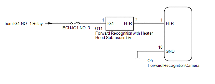
The forward recognition camera controls the flow of current to the forward recognition with heater hood sub-assembly.
If the forward recognition camera detects a malfunction in the forward recognition with heater hood sub-assembly circuit, it will store this DTC.
|
DTC No. | Detection Item |
DTC Detection Condition | Trouble Area |
|---|---|---|---|
|
C1AAE | Heater Circuit | Either of the following conditions is met after 2 seconds have elapsed since the engine switch was turned on (IG):
|
|
WIRING DIAGRAM
CAUTION / NOTICE / HINT
NOTICE:
Click here 
PROCEDURE
|
1. | CHECK FOR DTCs |
(a) Clear the DTCs.
Chassis > Front Recognition Camera > Clear DTCs(b) Make sure that the DTC detection conditions are met.
HINT:
If the detection conditions are not met, the system cannot detect the malfunction.
(c) Check for DTCs.
Chassis > Front Recognition Camera > Trouble Codes|
Result | Proceed to |
|---|---|
|
DTC C1AAE is not output |
A |
| DTC C1AAE is output |
B |
| A |
 | USE SIMULATION METHOD TO CHECK |
|
| 2. |
INSPECT FORWARD RECOGNITION WITH HEATER HOOD SUB-ASSEMBLY |
(a) Turn the engine switch off.
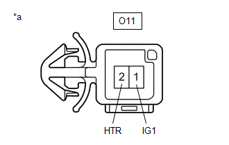
| (b) Disconnect the O11 forward recognition with heater hood sub-assembly connector. |
|
(c) Measure the resistance according to the value(s) in the table below.
Standard Resistance:
|
Tester Connection | Condition |
Specified Condition |
|---|---|---|
|
O11-1 (IG1) - O11-2 (HTR) |
Engine switch off | 38 to 42 Ω |
(d) Connect the O11 forward recognition with heater hood sub-assembly connector.
| NG | | REPLACE FORWARD RECOGNITION WITH HEATER HOOD SUB-ASSEMBLY |
|
| 3. |
CHECK HARNESS AND CONNECTOR (POWER SOURCE VOLTAGE) |
| (a) Disconnect the O11 forward recognition with heater hood sub-assembly connector. |
|
(b) Measure the voltage according to the value(s) in the table below.
Standard Voltage:
|
Tester Connection | Condition |
Specified Condition |
|---|---|---|
|
O11-1 (IG1) - Body ground |
Engine switch on (IG) |
11 to 14 V |
|
Engine switch off | Below 1.5 V |
(c) Connect the O11 forward recognition with heater hood sub-assembly connector.
| NG | | REPAIR OR REPLACE HARNESS OR CONNECTOR (POWER SOURCE CIRCUIT) |
|
| 4. |
CHECK HARNESS AND CONNECTOR (FORWARD RECOGNITION WITH HEATER HOOD SUB-ASSEMBLY - FORWARD RECOGNITION CAMERA) |
(a) Disconnect the O11 forward recognition with heater hood sub-assembly connector.
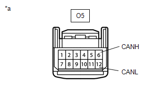
(b) Disconnect the O5 forward recognition camera connector.
(c) Measure the resistance according to the value(s) in the table below.
Standard Resistance:
|
Tester Connection | Condition |
Specified Condition |
|---|---|---|
|
O11-2 (HTR) - O5-1 (HTR) |
Always | Below 1 Ω |
|
O11-2 (HTR) or O5-1 (HTR) - Body ground |
Always | 10 kΩ or higher |
(d) Connect the O5 forward recognition camera connector.
(e) Connect the O11 forward recognition with heater hood sub-assembly connector.
| NG | | REPAIR OR REPLACE HARNESS OR CONNECTOR (FORWARD RECOGNITION WITH HEATER HOOD SUB-ASSEMBLY - FORWARD RECOGNITION CAMERA) |
|
| 5. |
CHECK HARNESS AND CONNECTOR (FORWARD RECOGNITION CAMERA - BODY GROUND) |
(a) Turn the engine switch off.
(b) Disconnect the O5 forward recognition camera connector.
(c) Measure the resistance according to the value(s) in the table below.
Standard Resistance:
|
Tester Connection | Condition |
Specified Condition |
|---|---|---|
|
O5-10 (GND) - Body ground |
Always | Below 1 Ω |
(d) Connect the O5 forward recognition camera connector.
| OK | | REPLACE FORWARD RECOGNITION CAMERA |
| NG | | REPAIR OR REPLACE HARNESS OR CONNECTOR (FORWARD RECOGNITION CAMERA - BODY GROUND) |
DATA LIST / ACTIVE TEST
DATA LIST
NOTICE:
In the table below, the values listed under "Normal Condition" are reference values. Do not depend solely on these reference values when deciding whether a part is faulty or not.
HINT:
Using the Techstream to read the Data List allows the values or states of switches, sensors, actuators and other items to be read without removing any parts. This non-intrusive inspection can be very useful because intermittent conditions or signals may be discovered before parts or wiring is disturbed. Reading the Data List information early in troubleshooting is one way to save diagnostic time.
(a) Connect the Techstream to the DLC3.
(b) Turn the engine switch on (IG).
(c) Turn the Techstream on.
(d) Enter the following menus: Chassis / Front Recognition Camera / Data List.
(e) Read the Data List according to the display on the Techstream.
Chassis > Front Recognition Camera > Data List|
Tester Display | Measurement Item |
Range | Normal Condition |
Diagnostic Note |
|---|---|---|---|---|
|
Blockage Status | Camera obstruction malfunction status |
ON or OFF | ON: Forward recognition camera obstructed OFF: Forward recognition camera not obstructed |
- |
| Blockage History |
Camera obstruction history status |
ON or OFF | ON: Forward recognition camera obstruction history exists OFF: Forward recognition camera obstruction history does not exist |
- |
| Low Temperature Status |
Low temperature malfunction status |
ON or OFF | ON: Forward recognition camera low temperature malfunction exists OFF: Forward recognition camera low temperature malfunction does not exist |
- |
| Low Temperature History |
Low temperature history status |
ON or OFF | ON: Forward recognition camera low temperature history exists OFF: Forward recognition camera low temperature history does not exist |
- |
| High Temperature Status1 |
High temperature malfunction status |
ON or OFF | ON: Forward recognition camera high temperature malfunction exists OFF: Forward recognition camera high temperature malfunction does not exist |
- |
| High Temperature History1 |
High temperature history status |
ON or OFF | ON: Forward recognition camera high temperature history exists OFF: Forward recognition camera high temperature history does not exist |
- |
| High Temperature Status2 |
High temperature malfunction status |
ON or OFF | ON: Forward recognition camera high temperature malfunction exists OFF: Forward recognition camera high temperature malfunction does not exist |
- |
| High Temperature History2 |
High temperature history status |
ON or OFF | ON: Forward recognition camera high temperature history exists OFF: Forward recognition camera high temperature history does not exist |
- |
| Backlight Status |
Backlight Status | OFF or Driving Backlight |
OFF: Not driving towards the sun Driving Backlight: Driving towards the sun |
- |
| Vehicle Information (2WD/4WD) |
Vehicle information (drivetrain) stored in forward recognition camera |
2WD, 4WD or Unknown | 2WD: for 2WD 4WD: for AWD Unknown: Vehicle information not confirmed |
- |
| Vehicle Information (Conv/HV) |
Vehicle information (conventional/hybrid) stored in forward recognition camera |
Conv, HV or Unknown | Conv: Conventional HV: Hybrid vehicle Unknown: Vehicle information not confirmed |
- |
| Heater Connection |
Forward recognition with heater hood sub-assembly connection state |
ON or OFF | ON: Forward recognition with heater hood sub-assembly connected OFF: Forward recognition with heater hood sub-assembly not connected |
- |
| Heater Control Status |
Forward recognition with heater hood sub-assembly control state |
Permit or Prohibit | Permit: Control permitted Prohibit: Control prohibited |
- |
| Heater Activation |
Forward recognition with heater hood sub-assembly operation state |
ON or OFF | ON: Forward recognition with heater hood sub-assembly operating OFF: Forward recognition with heater hood sub-assembly not operating |
- |
ACTIVE TEST
HINT:
Using the Techstream to perform Active Tests allows relays, VSVs, actuators and other items to be operated without removing any parts. This non-intrusive functional inspection can be very useful because intermittent operation may be discovered before parts or wiring is disturbed. Performing Active Tests early in troubleshooting is one way to save diagnostic time. Data List information can be displayed while performing Active Tests.
(a) Connect the Techstream to the DLC3.
(b) Turn the engine switch on (IG).
(c) Turn the Techstream on.
(d) Enter the following menus: Chassis / Front Recognition Camera / Active Test.
(e) Perform Active Test according to the display on the Techstream.
HINT:
The engine switch must be turned on (IG) to proceed with the Active Test using the Techstream.
Chassis > Front Recognition Camera > Active Test|
Tester Display | Measurement Item |
Control Range | Diagnostic Note |
|---|---|---|---|
|
PCS Buzzer | Sounds PCS Buzzer |
ON/OFF | Test possible with engine switch on (IG), vehicle stopped |
DIAGNOSTIC TROUBLE CODE CHART
Front Camera System|
DTC No. | Detection Item |
Link |
|---|---|---|
| C1A10 |
Front Radar Sensor |
|
|
C1A11 | Front Radar Sensor Incorrect Axial Gap |
|
|
C1A14 | Front Radar Sensor Beam Axis Not Adjusted |
|
|
C1AA0 | Front Camera Module Circuit |
|
|
C1AA1 | FCM Destination Information Unmatched |
|
|
C1AA3 | Vehicle Speed Sensor Circuit |
|
|
C1AA4 | Yaw Rate Sensor Circuit |
|
|
C1AA5 | Yaw Rate Sensor Power Supply Voltage Circuit |
|
|
C1AA6 | Yaw Rate Sensor Zero Point Malfunction |
|
|
C1AA9 | Front Camera Module Beam Axis Not Adjusted |
|
|
C1AAA | FCM Destination Information Uninitialized |
|
|
C1AAE | Heater Circuit |
|
|
U0100 | Lost Communication with ECM / PCM "A" |
|
|
U0101 | Lost Communication with TCM |
|
|
U0123 | Lost Communication with Yaw Rate Sensor Module |
|
|
U0129 | Lost Communication with Brake System Control Module |
|
|
U0142 | Lost Communication with Body Control Module "B" |
|
|
U0235 | Lost Communication with Cruise Control Front Distance Range Sensor |
|
|
U1104 | Lost Communication with Driving Support ECU |
|
DTC CHECK / CLEAR
CHECK DTC
(a) Connect the Techstream to the DLC3.
(b) Turn the engine switch on (IG).
(c) Turn the Techstream on.
(d) Enter the following menus: Chassis / Front Recognition Camera / Trouble Codes.
(e) Check for details of the DTCs.
Click here

CLEAR DTC
(a) Connect the Techstream to the DLC3.
(b) Turn the engine switch on (IG).
(c) Turn the Techstream on.
(d) Enter the following menus: Chassis / Front Recognition Camera / Clear DTCs.
(e) Clear the DTCs.
Chassis > Front Recognition Camera > Clear DTCsFREEZE FRAME DATA
DESCRIPTION
(a) Whenever a front camera system DTC is stored, the forward recognition camera stores the current vehicle state (ECU and sensor information) as Freeze Frame Data.
CHECK FREEZE FRAME DATA
(a) Connect the Techstream to the DLC3.
(b) Turn the engine switch on (IG).
(c) Turn the Techstream on.
(d) Enter the following menus: Chassis / Front Recognition Camera / Trouble Codes.
Chassis > Front Recognition Camera > Trouble Codes(e) According to the display on the Techstream, select a DTC with freeze frame data.
(f) Read the freeze frame data recorded when the DTC was stored.
Chassis > Front Recognition Camera|
Tester Display | Measurement Item |
Range | Normal Condition |
Diagnostic Note |
|---|---|---|---|---|
|
Blockage Status | Camera obstruction malfunction status |
ON or OFF | ON: Forward recognition camera obstructed OFF: Forward recognition camera not obstructed |
- |
| Blockage History |
Camera obstruction history status |
ON or OFF | ON: Forward recognition camera obstruction history exists OFF: Forward recognition camera obstruction history does not exist |
- |
| Low Temperature Status |
Low temperature malfunction status |
ON or OFF | ON: Forward recognition camera low temperature malfunction exists OFF: Forward recognition camera low temperature malfunction does not exist |
- |
| Low Temperature History |
Low temperature history status |
ON or OFF | ON: Forward recognition camera low temperature history exists OFF: Forward recognition camera low temperature history does not exist |
- |
| High Temperature Status1 |
High temperature malfunction status |
ON or OFF | ON: Forward recognition camera high temperature malfunction exists OFF: Forward recognition camera high temperature malfunction does not exist |
- |
| High Temperature History1 |
High temperature history status |
ON or OFF | ON: Forward recognition camera high temperature history exists OFF: Forward recognition camera high temperature history does not exist |
- |
| High Temperature Status2 |
High temperature malfunction status |
ON or OFF | ON: Forward recognition camera high temperature malfunction exists OFF: Forward recognition camera high temperature malfunction does not exist |
- |
| High Temperature History2 |
High temperature history status |
ON or OFF | ON: Forward recognition camera high temperature history exists OFF: Forward recognition camera high temperature history does not exist |
- |
| Backlight Status |
Backlight Status | OFF or Driving Backlight |
OFF: Not driving towards the sun Driving Backlight: Driving towards the sun |
- |
| Vehicle Information (2WD/4WD) |
Vehicle information (drivetrain) stored in forward recognition camera |
2WD, 4WD or Unknown | 2WD: for 2WD 4WD: for AWD Unknown: Vehicle information not confirmed |
- |
| Vehicle Information (Conv/HV) |
Vehicle information (conventional/hybrid) stored in forward recognition camera |
Conv, HV or Unknown | Conv: Conventional HV: Hybrid vehicle Unknown: Vehicle information not confirmed |
- |
CAUTION / NOTICE / HINT
HINT:
PROCEDURE
|
1. | VEHICLE BROUGHT TO WORKSHOP |
|
| 2. |
INSPECT BATTERY VOLTAGE |
(a) Measure the battery voltage.
Standard Voltage:
11 to 14 V
If the voltage is below 11 V, replace or recharge the battery before proceeding to the next step.
|
| 3. |
CHECK CAN COMMUNICATION SYSTEM* |
(a) Using the Techstream, check if the CAN communication system is functioning normally.
HINT:
Refer to CAN Bus Check in CAN Communication System.
Click here

OK:
CAN communication system is functioning normally.
| NG |  | GO TO CAN COMMUNICATION SYSTEM |
|
| 4. |
CHECK FOR DTCs* |
HINT:
Refer to DTC Check / Clear.
Click here
(a) Check for DTCs and note any codes that are output.
Chassis > Front Recognition Camera > Trouble Codes(b) Clear the DTCs.
Chassis > Front Recognition Camera > Clear DTCs(c) Recheck for DTCs. Try to reproduce the DTCs by duplicating the conditions indicated by the DTCs.
Chassis > Front Recognition Camera > Trouble Codes|
Result | Proceed to |
|---|---|
|
DTCs are not output | A |
|
DTCs are output | B |
| B |
| GO TO DTC CHART |
|
| 5. |
PROBLEM SYMPTOMS TABLE |
HINT:
Refer to Problem Symptoms Table.
Click here
|
Result | Proceed to |
|---|---|
|
Fault is not listed in Problem Symptoms Table |
A |
| Fault is listed in Problem Symptoms Table |
B |
| B |
| GO TO STEP 7 |
|
| 6. |
OVERALL ANALYSIS AND TROUBLESHOOTING* |
(a) Terminals of ECU
Click here
(b) Data List / Active Test
Click here
|
| 7. |
ADJUST, REPAIR OR REPLACE |
NOTICE:
If the forward recognition camera has been replaced with a new one, it is necessary to perform forward recognition camera adjustment.
Click here
|
| 8. |
CONFIRMATION TEST |
| NEXT | | END |
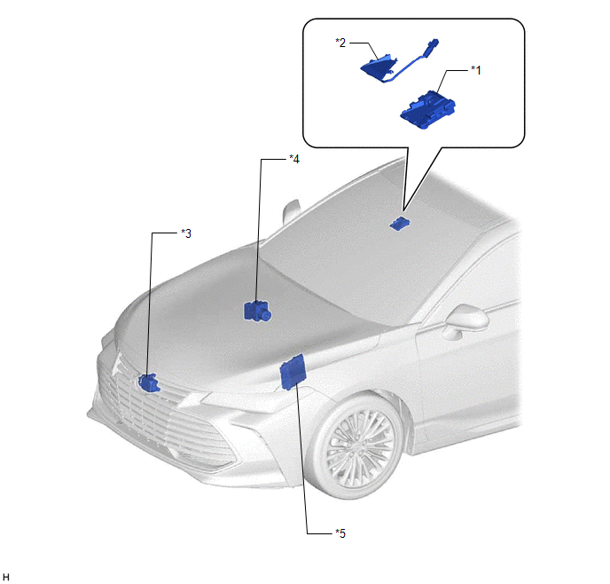
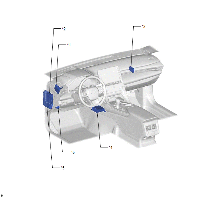
PARTS LOCATION
ILLUSTRATION
|
*1 | FORWARD RECOGNITION CAMERA |
*2 | FORWARD RECOGNITION WITH HEATER HOOD SUB-ASSEMBLY |
|
*3 | MILLIMETER WAVE RADAR SENSOR ASSEMBLY |
*4 | BRAKE ACTUATOR ASSEMBLY - SKID CONTROL ECU |
|
*5 | ECM |
- | - |
ILLUSTRATION
|
*1 | DRIVING SUPPORT ECU ASSEMBLY |
*2 | MAIN BODY ECU (MULTIPLEX NETWORK BODY ECU) |
|
*3 | CENTRAL GATEWAY ECU (NETWORK GATEWAY ECU) |
*4 | AIRBAG ECU ASSEMBLY - YAW RATE SENSOR |
|
*5 | INSTRUMENT PANEL JUNCTION BLOCK ASSEMBLY - ECU-IG1 NO. 3 FUSE |
*6 | DLC3 |
PRECAUTION
PRECAUTION FOR DISCONNECTING CABLE FROM NEGATIVE BATTERY TERMINAL
NOTICE:
When disconnecting the cable from the negative (-) battery terminal, initialize the following systems after the cable is reconnected.
|
System Name | See Procedure |
|---|---|
|
Lane Departure Alert System (w/ Steering Control) |
|
|
Pre-collision System | |
|
Intelligent Clearance Sonar System | |
|
Lighting System (w/ Cornering Light) | |
|
Parking Assist Monitor System | |
|
Panoramic View Monitor System |
PRECAUTIONS FOR SERVICING VEHICLE EQUIPPED WITH FORWARD RECOGNITION CAMERA
(a) When running the vehicle on a chassis dynamometer, cover the area in front of the forward recognition camera to prevent it from operating.
HINT:
HANDLING PRECAUTIONS FOR FORWARD RECOGNITION CAMERA
(a) The forward recognition camera is a precision part. Be sure to observe the following precautions when handling it.
(1) Do not apply excessive force to the forward recognition camera or subject it to a strong impact.
(2) Do not disassemble the forward recognition camera.
(3) Do not change the installation position of the forward recognition camera or modify the surrounding components.
(4) Do not touch the forward recognition camera lens when replacing the forward recognition camera.
HINT:
If the forward recognition camera lens is touched, replace the forward recognition camera with a new one.
PRECAUTION FOR REPLACING FORWARD RECOGNITION CAMERA
(a) If the forward recognition camera has been replaced with a new one or the windshield glass has been removed and installed, it is necessary to perform forward recognition camera adjustment. If the system is turned on without performing forward recognition camera adjustment, DTC C1AA9 will be stored.
Click here 
(b) When replacing the forward recognition camera, replace it with a new one. If a forward recognition camera which was installed to another vehicle is used, the information stored in the forward recognition camera will not match the information from the vehicle and a DTC may be stored.
(c) When replacing the forward recognition camera, do not damage the camera lens or allow it to become contaminated with foreign matter.
(d) Do not reuse a forward recognition camera that has been dropped or subjected to a strong impact.
HANDLING PRECAUTIONS FOR CAN COMMUNICATION SYSTEM
(a) First check the CAN communication system by following How to Proceed with Troubleshooting. After checking that there are no malfunctions in the CAN communication system, proceed with troubleshooting.
Click here
PRECAUTIONS FOR COMPONENTS SURROUNDING FORWARD RECOGNITION CAMERA
(a) Be sure to use Toyota genuine front wiper blades.
HINT:
If non-Toyota genuine parts are used, the forward recognition camera view may be blocked, affecting the operation of systems that use the forward recognition camera.
(b) Be sure to replace the wiper rubbers before they wear out.
HINT:
If streaks are left on the windshield glass, the forward recognition camera may not operate properly, affecting the operation of systems that use the forward recognition camera.
(c) Do not install any accessories to the front of the vehicle such as the engine hood or front grill.
HINT:
The forward recognition camera view may be blocked, affecting the operation of systems that use the forward recognition camera.
(d) Do not allow any objects mounted on the roof rack to obstruct the area in front of the forward recognition camera.
HINT:
The forward recognition camera view may be blocked, affecting the operation of systems that use the forward recognition camera.
(e) Keep the windshield glass clean.
HINT:
If the windshield glass is dirty, fogged up or has an oily film, the forward recognition camera may not operate properly, affecting the operation of systems that use the forward recognition camera.
(f) Do not attach any stickers or install any accessories to the area of the windshield glass in front of the forward recognition camera.
HINT:
(g) Even if a water repellent glass coating is applied to the windshield, it is still necessary to use the wipers if the area in front of the forward recognition camera is covered with water droplets.
(h) If the windshield glass is chipped or cracked, replace it.
(i) When replacing the windshield glass of a vehicle equipped with a forward recognition camera, make sure to use a Toyota genuine part.
HINT:
If a non-Toyota genuine part is used, the forward recognition camera may not be able to be installed due to a missing bracket or the front camera system may not operate properly due to a difference in the transmissivity or black ceramic border.
FEATURES OF FORWARD RECOGNITION CAMERA
(a) The forward recognition camera has characteristics similar to those of human eyes. When the visibility is poor for the driver, the forward recognition camera may not properly detect lane markers or vehicles and objects on the road ahead.
(b) Only the objects in the forward recognition camera detection area can be detected.
(c) The forward recognition camera has a function to detect foreign matter in the area in front of the forward recognition camera.
HINT:
The forward recognition camera may not always detect dirt in the area in front of the forward recognition camera.
(d) In the following situations, the forward recognition camera may not detect objects such as a preceding vehicle, pedestrians or lane makers:
(1) When driving in inclement weather such as heavy rain or snow, dense fog, a sandstorm, etc.
(2) When the view of the forward recognition camera is obscured by steam, sand, smoke, water, snow or dust.
(3) When an intensely bright light, such as the sun or high beams of an oncoming vehicle shine directly into the forward recognition camera.
(4) When the surrounding area is dim, such as at dawn or dusk.
(5) When the headlights of the vehicle are turned off at night or in a tunnel.
(6) The contrast of the area around the vehicle is poor due to snow, etc.
(7) When the ambient temperature is low, the heater is operating with FOOT mode selected.
HINT:
If the upper area of the windshield glass fogs up, the system may not operate.
(e) In the following situations, the forward recognition camera may not detect objects appropriately:
(1) When the vehicle is being driven where a sudden change in brightness occurs, such as at the entrance or exit of a tunnel or in the shade.
(2) When the forward recognition camera is facing upward or downward due to inclination of the vehicle when overloaded.
(3) When the vehicle height is not standard due to modified suspension or non-standard tires.
(4) When the windshield glass is covered with water drops, snow, ice, dirt, frost, dust, oil, etc.
(5) When the windshield glass is fogged-up.
(6) When rain drops, washer fluid, or a wiper blade blocks the forward recognition camera.
(7) An object mounted on the roof rack is obstructing the area in front of the forward recognition camera.
(f) The front camera system may not operate properly in any of the following conditions:
(1) The forward recognition camera is misaligned or damaged due to a strong impact being applied to the camera or the area around it.
(2) The cabin temperature is extremely high.
(3) The cabin temperature is extremely low.
(4) Immediately after the engine is started.
PROBLEM SYMPTOMS TABLE
HINT:
|
Symptom | Suspected Area |
Link |
|---|---|---|
|
The message "Front Camera Unavailable Remove Debris On Windshield" is frequently displayed |
Non-Toyota genuine front wiper blades are installed |
- |
| The front wiper rubbers are worn |
- | |
| A sticker, accessory or other object is obstructing the forward recognition camera |
- | |
| There is snow, frost, dirt, dust or oil on the windshield glass, or the windshield glass is fogged up |
- | |
| A glass coating has been applied to the windshield glass |
- | |
| The windshield glass is chipped or cracked |
- | |
| Non-Toyota genuine windshield glass is installed |
- | |
| Forward recognition camera |
| |
|
The message "Front Camera Unavailable" is frequently displayed |
Immediately after the engine is started |
- |
| The cabin temperature is extremely high |
- | |
| The cabin temperature is extremely low |
- | |
| Forward recognition camera |
| |
|
A system that uses the forward recognition camera does not operate |
Forward recognition camera |
|
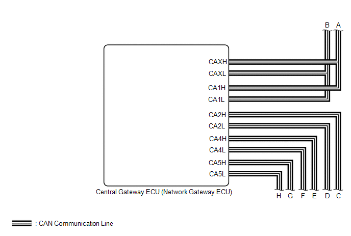
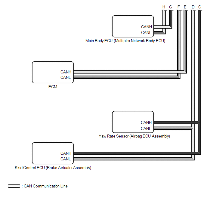
SYSTEM DIAGRAM
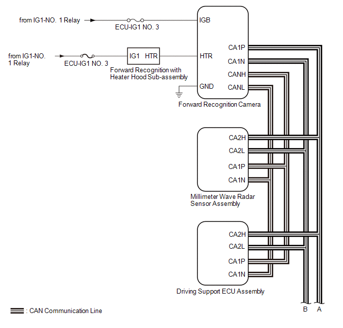
 Communication Table
 |
Sender | Receiver |
Signal | Line |
|---|---|---|---|
|
Forward Recognition Camera | Main Body ECU (Multiplex Network Body ECU) |
Automatic high beam control signal |
CAN |
| Driving Support ECU Assembly |
Forward Recognition Camera | PCS control information signal |
CAN |
| ECM |
Forward Recognition Camera |
| CAN |
|
Main Body ECU (Multiplex Network Body ECU) |
Forward Recognition Camera | Vehicle specification information (destination) |
CAN |
| Skid Control ECU (Brake Actuator Assembly) |
Forward Recognition Camera |
| CAN |
|
Yaw Rate Sensor (Airbag ECU Assembly) |
Forward Recognition Camera | Vehicle yaw rate sensor signal |
CAN |
TERMINALS OF ECU
NOTICE:

CHECK FORWARD RECOGNITION CAMERA
(a) Measure the voltage and resistance according to the value(s) in the table below.
|
Terminal No. (Symbol) | Wiring Color |
Terminal Description | Condition |
Specified Condition |
|---|---|---|---|---|
|
O5-7 (IGB) - O5-10 (GND) |
LA-P - LA |
Power source | Engine switch on (IG) |
11 to 14 V |
|
Engine switch off | Below 1 V | |||
|
O5-10 (GND) - Body ground |
LA - Body ground | Ground |
Always | Below 1 Ω |
(b) Measure the voltage according to the value(s) in the table below.
|
Terminal No. (Symbol) | Wiring Color |
Terminal Description | Condition |
Specified Condition |
|---|---|---|---|---|
|
O5-1 (HTR) - O5-10 (GND) |
B - LA | Forward recognition with heater hood sub-assembly operation signal |
Engine switch on (IG) Forward recognition with heater hood sub-assembly not operating |
11 to 14 V |
|
Engine switch on (IG) Forward recognition with heater hood sub-assembly operating |
Below 1 V |
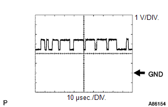
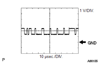
(c) Check for pulses according to the value(s) in the table below.
HINT:
If the waveform is not similar to that shown in the illustration, a malfunction of a CAN bus line, terminating resistor, or the forward recognition camera is suspected.
|
Terminal No. (Symbol) | Wiring Color |
Terminal Description | Condition |
Specified Condition |
|---|---|---|---|---|
|
O5-5 (CA1P) - O5-10 (GND) |
L - LA | CAN communication signal |
Engine switch on (IG) |
Pulse generation (See waveform 1) |
|
O5-11 (CA1N) - O5-10 (GND) |
W - LA | CAN communication signal |
Engine switch on (IG) |
Pulse generation (See waveform 2) |
|
O5-6 (CANH) - O5-10 (GND) |
G - LA | CAN communication signal |
Engine switch on (IG) |
Pulse generation (See waveform 1) |
|
O5-12 (CANL) - O5-10 (GND) |
W - LA | CAN communication signal |
Engine switch on (IG) |
Pulse generation (See waveform 2) |
(1) WAVEFORM 1
|
Item | Content |
|---|---|
|
Terminal Name | Between O5-5 (CA1P) and O5-10 (GND) Between O5-6 (CANH) and O5-10 (GND) |
|
Tester Range | 1 V/DIV., 10 μsec./DIV. |
|
Condition | Engine switch on (IG) |
HINT:
The waveform varies depending on the CAN communication signal.
(2) WAVEFORM 2
|
Item | Content |
|---|---|
|
Terminal Name | Between O5-11 (CA1N) and O5-10 (GND) Between O5-12 (CANL) and O5-10 (GND) |
|
Tester Range | 1 V/DIV., 10 μsec./DIV. |
|
Condition | Engine switch on (IG) |
HINT:
The waveform varies depending on the CAN communication signal.
DESCRIPTION
When a malfunction is detected between various ECUs and sensors, these DTCs are stored.
|
DTC No. | Detection Item |
DTC Detection Condition | Trouble Area |
|---|---|---|---|
|
U0100 | Lost Communication with ECM / PCM "A" |
While the vehicle is being driven at 1 km/h or 1 mph or more, a communication error between the ECM and the forward recognition camera is detected for approximately 5 seconds or more. |
CAN communication system |
|
U0101 | Lost Communication with TCM |
While the vehicle is being driven at 1 km/h or 1 mph or more, a communication error between the TCM (ECM) and the forward recognition camera is detected for approximately 5 seconds or more. |
CAN communication system |
|
U0123 | Lost Communication with Yaw Rate Sensor Module |
While the vehicle is being driven at 1 km/h or 1 mph or more, a communication error between the yaw rate sensor (airbag ECU assembly) and the forward recognition camera is detected for approximately 5 seconds or more. |
CAN communication system |
|
U0129 | Lost Communication with Brake System Control Module |
2 seconds after the engine switch is turned on (IG), a communication error between the skid control ECU (brake actuator assembly) and the forward recognition camera is detected for approximately 5 seconds or more. | CAN communication system |
|
U0142 | Lost Communication with Body Control Module "B" |
2 seconds after the engine switch is turned on (IG), a communication error between the main body ECU (multiplex network body ECU) and the forward recognition camera is detected for approximately 5 seconds or more. | CAN communication system |
PROCEDURE
| 1. |
CHECK FOR DTCs |
(a) Clear the DTCs.
Chassis > Front Recognition Camera > Clear DTCs(b) Make sure that the DTC detection conditions are met.
HINT:
If the detection conditions are not met, the system cannot detect the malfunction.
(c) Check for DTCs.
Chassis > Front Recognition Camera > Trouble Codes|
Result | Proceed to |
|---|---|
|
DTC U0100, U0101, U0123, U0129 and U0142 are not output |
A |
| DTC U0100, U0101, U0123, U0129 or U0142 is output |
B |
| A |
 | USE SIMULATION METHOD TO CHECK |
| B |
| GO TO CAN COMMUNICATION SYSTEM |
DESCRIPTION
The forward recognition camera communicates with the millimeter wave radar sensor assembly via CAN communication. If there is a communication error with the millimeter wave radar sensor assembly, the forward recognition camera stores DTC U0235.
|
DTC No. | Detection Item |
DTC Detection Condition | Trouble Area |
|---|---|---|---|
|
U0235 | Lost Communication with Cruise Control Front Distance Range Sensor |
2 seconds after the engine switch is turned on (IG), a communication error between the millimeter wave radar sensor assembly and the forward recognition camera is detected for approximately 5 seconds. |
|
WIRING DIAGRAM

CAUTION / NOTICE / HINT
NOTICE:
Click here 
Click here
PROCEDURE
|
1. | READ VALUE USING TECHSTREAM (CAN BUS CHECK) |
(a) Connect the Techstream to the DLC3.
(b) Turn the engine switch on (IG).
(c) Turn the Techstream on.
(d) Enter the following menus: System Select / Can Bus Check.
Click here
|
Result | Proceed to |
|---|---|
|
All of the ECUs and sensors that are currently connected to the CAN communication system are displayed |
A |
| None of the ECUs and sensors that are currently connected to the CAN communication system are displayed, or some of them are not displayed |
B |
| B |
 | GO TO CAN COMMUNICATION SYSTEM |
|
| 2. |
CHECK FOR DTCs |
HINT:
When pre-collision system DTC U1002 is output, check that the local bus is functioning normally by performing the diagnostic procedure for U1002.
(a) Check for DTCs.
Body Electrical > Pre-Collision 2 > Trouble Codes|
Result | Proceed to |
|---|---|
|
DTC U1002 is not output |
A |
| DTC U1002 is output |
B |
| B |
| GO TO PRE-COLLISION SYSTEM |
|
| 3. |
CHECK CAN BUS LINE |
(a) Turn the engine switch off.
(b) Disconnect the cable from the negative (-) battery terminal.
| (c) Disconnect the O5 forward recognition camera connector. |
|
(d) Measure the resistance according to the value(s) in the table below.
Standard Resistance:
|
Tester Connection | Condition |
Specified Condition |
|---|---|---|
|
O5-6 (CANH) - O5-12 (CANL) |
Cable disconnected from negative (-) battery terminal |
108 to 132 Ω |
HINT:
If the result is not as specified, a malfunction in a CAN communication line is suspected.
(e) Connect the O5 forward recognition camera connector.
| NG | | REPAIR OR REPLACE HARNESS OR CONNECTOR (CAN BUS LINE) |
|
| 4. |
CHECK FOR DTCs |
(a) Check for DTCs.
Chassis > Front Recognition Camera > Trouble Codes|
Result | Proceed to |
|---|---|
|
Only DTC U0235 is output |
A |
| DTC U0235 and U1104 are output |
B |
| B |
| REPLACE FORWARD RECOGNITION CAMERA |
|
| 5. |
CHECK FOR DTCs |
(a) Check for DTCs.
HINT:
The malfunction area can be determined by the combination of DTCs output at the same time.
Body Electrical > Pre-Collision 2 > Trouble Codes Chassis > Front Recognition Camera > Trouble Codes|
Result | Proceed to |
|---|---|
|
Front camera system (Front Recognition Camera) DTC U0235 and pre-collision system (Pre-Collision 2) DTC U1104 are output. |
A |
| Front camera system (Front Recognition Camera) DTC U0235 and pre-collision system (Pre-Collision 2) DTC U0235 are output. | |
|
Only front camera system (Front Recognition Camera) DTC U0235 is output. |
B |
| A |
| REPLACE MILLIMETER WAVE RADAR SENSOR ASSEMBLY |
| B |
| REPLACE FORWARD RECOGNITION CAMERA |
DESCRIPTION
The forward recognition camera communicates with the driving support ECU assembly via CAN communication. If there is a communication error with the driving support ECU assembly, the forward recognition camera store DTC U1104.
|
DTC No. | Detection Item |
DTC Detection Condition | Trouble Area |
|---|---|---|---|
|
U1104 | Lost Communication with Driving Support ECU |
2 seconds after the engine switch is turned on (IG), a communication error between the driving support ECU assembly and the forward recognition camera is detected for approximately 5 seconds. |
|
WIRING DIAGRAM
CAUTION / NOTICE / HINT
NOTICE:
Click here 
PROCEDURE
|
1. | READ VALUE USING TECHSTREAM (CAN BUS CHECK) |
(a) Connect the Techstream to the DLC3.
(b) Turn the engine switch on (IG).
(c) Turn the Techstream on.
(d) Enter the following menus: System Select / Can Bus Check.
Click here
|
Result | Proceed to |
|---|---|
|
All of the ECUs and sensors that are currently connected to the CAN communication system are displayed |
A |
| None of the ECUs and sensors that are currently connected to the CAN communication system are displayed, or some of them are not displayed |
B |
| B |
 | GO TO CAN COMMUNICATION SYSTEM |
|
| 2. |
CHECK CAN BUS LINE |
(a) Turn the engine switch off.
(b) Disconnect the cable from the negative (-) battery terminal.
| (c) Disconnect the O5 forward recognition camera connector. |
|
(d) Measure the resistance according to the value(s) in the table below.
Standard Resistance:
|
Tester Connection | Condition |
Specified Condition |
|---|---|---|
|
O5-6 (CANH) - O5-12 (CANL) |
Cable disconnected from negative (-) battery terminal |
108 to 132 Ω |
HINT:
If the result is not as specified, a malfunction in a CAN communication line is suspected.
(e) Connect the O5 forward recognition camera connector.
| NG | | REPAIR OR REPLACE HARNESS OR CONNECTOR (CAN BUS LINE) |
|
| 3. |
CHECK FOR DTCs |
(a) Check for DTCs.
Chassis > Front Recognition Camera > Trouble Codes|
Result | Proceed to |
|---|---|
|
Only DTC U1104 is output |
A |
| DTC U0235 and U1104 are output |
B |
| B |
| REPLACE FORWARD RECOGNITION CAMERA |
|
| 4. |
CHECK FOR DTCs |
(a) Check for DTCs.
HINT:
The malfunction area can be determined by the combination of DTCs output at the same time.
Body Electrical > Pre-Collision 2 > Trouble Codes Chassis > Front Recognition Camera > Trouble Codes|
Result | Proceed to |
|---|---|
|
Front camera system (Front Recognition Camera) DTC U1104 and pre-collision system (Pre-Collision 2) DTC U1002 are output. |
A |
| Front camera system (Front Recognition Camera) DTC U1104 and pre-collision system (Pre-Collision 2) DTC U1104 are output. |
B |
| Only front camera system (Front Recognition Camera) DTC U1104 is output. |
C |
| A |
| GO TO PRE-COLLISION SYSTEM |
| B |
| REPLACE DRIVING SUPPORT ECU ASSEMBLY |
| C |
| REPLACE FORWARD RECOGNITION CAMERA |
UTILITY
NOTICE:
Click here 
RECOGNITION CAMERA/TARGET POSITION MEMORY
HINT:
Recognition Camera/Target Position Memory is used to enter required information into the forward recognition camera.
(a) Perform Recognition Camera/Target Position Memory according to the display on the Techstream.
Click here
|
Tester Display |
|---|
| Recognition Camera/Target Position Memory |
HINT:
Recognition Camera Axis Adjust is used to calibrate the internal data of the forward recognition camera to enhance its recognition accuracy.
RECOGNITION CAMERA AXIS ADJUST
(a) Perform Recognition Camera Axis Adjust according to the display on the Techstream.
Click here
|
Tester Display |
|---|
| Recognition Camera Axis Adjust |
HINT:
History Clear is used to clear the history of Data List items Blockage, Low Temperature, or High Temperature.
HISTORY CLEAR
(a) Connect the Techstream to the DLC3.
(b) Turn the engine switch on (IG).
(c) Turn the Techstream on.
(d) Enter the following menus: Chassis / front recognition camera / Utility / History Clear.
(e) Perform History Clear according to the display on the Techstream.
Chassis > Front Recognition Camera > Utility|
Tester Display |
|---|
| History Clear |
PCS IMAGE INFORMATION CLEAR
HINT:
PCS Image Information Clear is used to clear the PCS Image Information data.
(a) Connect the Techstream to the DLC3.
(b) Turn the engine switch on (IG).
(c) Turn the Techstream on.
(d) Enter the following menus: Chassis / front recognition camera / Utility / PCS Image Information Clear.
(e) Perform PCS Image Information Clear according to the display on the Techstream.
Chassis > Front Recognition Camera > Utility|
Tester Display |
|---|
| PCS Image Information Clear |
PCS IMAGE RECORD SETTING
HINT:
PCS Image Record Setting is used to activate/deactivate the PCS image recording function.
(a) Connect the Techstream to the DLC3.
(b) Turn the engine switch on (IG).
(c) Turn the Techstream on.
(d) Enter the following menus: Chassis / front recognition camera / Utility / PCS Image Record Setting.
(e) Perform PCS Image Record Setting according to the display on the Techstream.
Chassis > Front Recognition Camera > Utility|
Tester Display |
|---|
| PCS Image Record Setting |
Toyota Avalon (XX50) 2019-2022 Service & Repair Manual > Hybrid Control System: Drive Motor "A" Temperature Sensor Circuit Short to Ground (P0A2A11,P0A2A15)
DTC SUMMARY MALFUNCTION DESCRIPTION These DTCs are stored when the motor temperature sensor output is abnormal. The cause of this malfunction may be one of the following: Hybrid vehicle control ECU malfunction Hybrid vehicle control ECU internal malfunction Motor temperature sensor malfunction Inter ...