DESCRIPTION
If the forward recognition camera detects a malfunction in the internal circuit of the driving support ECU assembly, DTC C1A01 is stored.
|
DTC No. | Detection Item |
DTC Detection Condition | Trouble Area |
|---|---|---|---|
|
C1A01 | Driving Support ECU |
2 seconds after the engine switch is turned on (IG), a malfunction in the driving support ECU assembly internal circuit is detected for 5 seconds or more. | Driving support ECU assembly |
CAUTION / NOTICE / HINT
NOTICE:
Click here 
PROCEDURE
|
1. | REPLACE DRIVING SUPPORT ECU ASSEMBLY |
(a) Replace the driving support ECU assembly.
Click here
| NEXT |  |
END |
DESCRIPTION
The forward recognition camera uses the millimeter wave radar sensor assembly to detect obstacles in front of the vehicle.
When the forward recognition camera receives information that there is an internal malfunction in the millimeter wave radar sensor assembly, DTC C1A10 is stored.
|
DTC No. | Detection Item |
DTC Detection Condition | Trouble Area |
|---|---|---|---|
|
C1A10 | Front Radar Sensor |
2 seconds after the engine switch is turned on (IG), a signal from the millimeter wave radar sensor assembly indicating that there is an internal malfunction in millimeter wave radar sensor assembly is detected by the forward recognition camera for 5 seconds or more. |
Millimeter wave radar sensor assembly |
CAUTION / NOTICE / HINT
NOTICE:
Click here 
Click here
PROCEDURE
|
1. | REPLACE MILLIMETER WAVE RADAR SENSOR ASSEMBLY |
(a) Replace the millimeter wave radar sensor assembly.
Click here
(b) Adjust the millimeter wave radar sensor assembly.
Click here
| NEXT |  | END |
DESCRIPTION
The forward recognition camera uses the millimeter wave radar sensor assembly to detect obstacles in front of the vehicle.
When the vehicle is determined to be driving in a straight line or on a gradual curve based on signals from the yaw rate sensor etc., the millimeter wave radar sensor assembly performs self diagnosis to check if the sensor beam axis has deviated from the vehicle movement direction. When the millimeter wave radar sensor assembly beam axis has deviated, the forward recognition camera detects this, and stores DTC C1A11.
After installing a new millimeter wave radar sensor assembly, if sensor beam axis adjustment is not performed, DTC C1A14 is stored.
|
DTC No. | Detection Item |
DTC Detection Condition | Trouble Area |
|---|---|---|---|
|
C1A11 | Front Radar Sensor Incorrect Axial Gap |
2 seconds after the engine switch is turned on (IG), misalignment of the millimeter wave radar sensor assembly is detected for approximately 5 seconds. | Pre-collision system |
|
C1A14 | Front Radar Sensor Beam Axis Not Adjusted |
2 seconds after the engine switch is turned on (IG), incompletion of the millimeter wave radar sensor assembly beam axis alignment is detected for approximately 5 seconds. | Pre-collision system |
PROCEDURE
| 1. |
GO TO PRE-COLLISION SYSTEM |
HINT:
If DTC C1A11 or C1A14 is output by the lane departure alert system (w/ steering control), perform troubleshooting for the pre-collision system.
Click here

| NEXT |  |
END |
DESCRIPTION
The forward recognition camera receives steering angle information from the steering sensor. If the forward recognition camera detects a steering sensor malfunction, DTC C1A47 is stored.
|
DTC No. | Detection Item |
DTC Detection Condition | Trouble Area |
|---|---|---|---|
|
C1A47 | Steering Angle Sensor |
2 seconds after the engine switch is turned on (IG), a signal from the steering sensor indicating that there is a steering sensor malfunction is detected by the forward recognition camera for 5 seconds or more. |
Electronically controlled brake system |
CAUTION / NOTICE / HINT
NOTICE:
The lane departure alert system (w/ steering control) uses the CAN communication system. First, confirm that there are no malfunctions in the CAN communication system. Refer to How to Proceed with Troubleshooting.
Click here 
PROCEDURE
| 1. |
GO TO ELECTRONICALLY CONTROLLED BRAKE SYSTEM |
HINT:
If DTC C1A47 is output by the lane departure alert system (w/ steering control), perform troubleshooting for the electronically controlled brake system.
Click here
| NEXT |  | END |
DESCRIPTION
The forward recognition camera receives G sensor signals from the airbag ECU assembly via CAN communication.
If the forward recognition camera receives a G sensor malfunction signal from the airbag ECU assembly, DTC C1A48 is stored.
|
DTC No. | Detection Item |
DTC Detection Condition | Trouble Area |
|---|---|---|---|
|
C1A48 | G Sensor |
2 seconds after the engine switch is turned on (IG), a signal from the airbag ECU assembly indicating that there is a G sensor malfunction is detected by the forward recognition camera for 5 seconds or more. |
Electronically controlled brake system |
CAUTION / NOTICE / HINT
NOTICE:
The lane departure alert system (w/ steering control) uses the CAN communication system. First, confirm that there are no malfunctions in the CAN communication system. Refer to How to Proceed with Troubleshooting.
Click here 
PROCEDURE
| 1. |
GO TO ELECTRONICALLY CONTROLLED BRAKE SYSTEM |
HINT:
If DTC C1A48 is output by the lane departure alert system (w/ steering control), perform troubleshooting for the electronically controlled brake system.
Click here
| NEXT |  | END |
DESCRIPTION
The forward recognition camera receives electronically controlled brake system control signals from the skid control ECU (brake actuator assembly). If the forward recognition camera receives a malfunction signal from the electronically controlled brake system, DTC C1A50 is stored.
|
DTC No. | Detection Item |
DTC Detection Condition | Trouble Area |
|---|---|---|---|
|
C1A50 | Brake System Malfunction |
2 seconds after the engine switch is turned on (IG), a signal from the skid control ECU (brake actuator assembly) indicating an electronically controlled brake system malfunction is detected by the forward recognition camera for 5 seconds or more. |
Electronically controlled brake system |
CAUTION / NOTICE / HINT
NOTICE:
The lane departure alert system (w/ steering control) uses the CAN communication system. First, confirm that there are no malfunctions in the CAN communication system. Refer to How to Proceed with Troubleshooting.
Click here 
PROCEDURE
| 1. |
GO TO ELECTRONICALLY CONTROLLED BRAKE SYSTEM |
HINT:
If DTC C1A50 is output by the lane departure alert system (w/ steering control), perform troubleshooting for the electronically controlled brake system.
Click here
| NEXT |  | END |
DESCRIPTION
If the forward recognition camera receives an internal malfunction signal from the power steering ECU (rack and pinion power steering gear assembly), DTC C1A70 is stored.
|
DTC No. | Detection Item |
DTC Detection Condition | Trouble Area |
|---|---|---|---|
|
C1A70 | Power Steering Control System |
2 seconds after the engine switch is turned on (IG), a malfunction in the power steering system internal circuit is detected for 5 seconds or more. | Power steering system |
CAUTION / NOTICE / HINT
NOTICE:
The lane departure alert system (w/ steering control) uses the CAN communication system. First, confirm that there are no malfunctions in the CAN communication system. Refer to How to Proceed with Troubleshooting.
Click here 
PROCEDURE
| 1. |
GO TO POWER STEERING SYSTEM |
HINT:
If DTC C1A70 is output by the lane departure alert system (w/ steering control), perform troubleshooting for the power steering system.
Click here
| NEXT |  |
END |
DESCRIPTION
If the power steering ECU (rack and pinion power steering gear assembly) detects an abnormality in the steering torque requested by the forward recognition camera, the power steering ECU (rack and pinion power steering gear assembly) sends a malfunction signal to the forward recognition camera, and DTC C1A71 is stored.
|
DTC No. | Detection Item |
DTC Detection Condition | Trouble Area |
|---|---|---|---|
|
C1A71 | Power Steering Control Torque |
2 seconds after the engine switch is turned on (IG), a malfunction signal from the power steering ECU (rack and pinion power steering gear assembly) is detected by the forward recognition camera for 5 seconds or more. | Power steering system |
CAUTION / NOTICE / HINT
NOTICE:
The lane departure alert system (w/ steering control) uses the CAN communication system. First, confirm that there are no malfunctions in the CAN communication system. Refer to How to Proceed with Troubleshooting.
Click here 
PROCEDURE
| 1. |
GO TO POWER STEERING SYSTEM |
HINT:
If DTC C1A71 is output by the lane departure alert system (w/ steering control), perform troubleshooting for the power steering system.
Click here
| NEXT |  |
END |
DESCRIPTION
If a communication error between the driving support ECU assembly and forward recognition camera is detected, DTC C1A72 is stored.
|
DTC No. | Detection Item |
DTC Detection Condition | Trouble Area |
|---|---|---|---|
|
C1A72 | Communication Error from FCM to Driving Support ECU |
2 seconds after the engine switch is turned on (IG), a communication error between the driving support ECU assembly and the forward recognition camera is detected. |
|
CAUTION / NOTICE / HINT
NOTICE:
Click here 
Click here
PROCEDURE
|
1. | CHECK FOR DTCs |
HINT:
Confirm that there is no communication error between the forward recognition camera and driving support ECU assembly.
(a) Check for DTCs.
Body Electrical > Pre-Collision 2 > Trouble Codes|
Result | Proceed to |
|---|---|
|
DTC U023A is not output |
A |
| DTC U023A is output |
B |
| B |
 | GO TO PRE-COLLISION SYSTEM |
|
| 2. |
CHECK FOR DTCs |
(a) Clear the DTCs.
Chassis > LKA/LDA > Clear DTCs(b) Make sure that the DTC detection conditions are met.
HINT:
If the detection conditions are not met, the system cannot detect the malfunction.
(c) Check for DTCs.
Chassis > LKA/LDA > Trouble Codes|
Result | Proceed to |
|---|---|
|
DTC C1A72 is not output |
A |
| DTC C1A72 is output |
B |
| A |
| USE SIMULATION METHOD TO CHECK |
| B |
| REPLACE FORWARD RECOGNITION CAMERA |
DESCRIPTION
If a communication error between the driving support ECU assembly and another ECU is detected, DTC C1A73 is stored.
|
DTC No. | Detection Item |
DTC Detection Condition | Trouble Area |
|---|---|---|---|
|
C1A73 | Driving Support ECU Receive Data Malfunction |
2 seconds after the engine switch is turned on (IG), a communication error between the driving support ECU assembly and other ECUs is detected 5 seconds or more. |
|
CAUTION / NOTICE / HINT
NOTICE:
Click here 
Click here
PROCEDURE
|
1. | CHECK FOR DTCs |
HINT:
The driving support ECU communicates with other ECUs via CAN communication. Confirm that the CAN communication system is functioning normally before proceeding.
(a) Check for DTCs.
Body Electrical > Pre-Collision 2 > Trouble Codes|
Result | Proceed to |
|---|---|
|
DTC U0100, U0125, U0126, U0129, U0155, U0235, U023A, U1002 and U1104 are not output |
A |
| DTC U0100, U0125, U0126, U0129, U0155, U0235, U023A, U1002 or U1104 are output |
B |
| B |
 | GO TO PRE-COLLISION SYSTEM |
|
| 2. |
CHECK FOR DTCs |
(a) Clear the DTCs.
Chassis > LKA/LDA > Clear DTCs(b) Make sure that the DTC detection conditions are met.
HINT:
If the detection conditions are not met, the system cannot detect the malfunction.
(c) Check for DTCs.
Chassis > LKA/LDA > Trouble Codes|
Result | Proceed to |
|---|---|
|
DTC C1A73 is not output |
A |
| DTC C1A73 is output |
B |
| A |
| USE SIMULATION METHOD TO CHECK |
| B |
| REPLACE FORWARD RECOGNITION CAMERA |
DESCRIPTION
When an internal malfunction is detected in the forward recognition camera, DTC C1AA0 is stored.
|
DTC No. | Detection Item |
DTC Detection Condition | Trouble Area |
|---|---|---|---|
|
C1AA0 | Front Camera Module Circuit |
2 seconds after the engine switch is turned on (IG), the forward recognition camera detects an internal malfunction. |
Forward recognition camera |
CAUTION / NOTICE / HINT
NOTICE:
Click here 
PROCEDURE
|
1. | REPLACE FORWARD RECOGNITION CAMERA |
(a) Replace the forward recognition camera.
Click here
(b) Perform forward recognition camera adjustment.
Click here
| NEXT |  | END |
DESCRIPTION
When the forward recognition camera is replaced with a new one, the new forward recognition camera attempts to store country specification information received from the main body ECU (multiplex network body ECU). If the country specification information stored in the forward recognition camera is different from that stored in the main body ECU (multiplex network body ECU), DTC C1AA1 is stored.
|
DTC No. | Detection Item |
DTC Detection Condition | Trouble Area |
|---|---|---|---|
|
C1AA1 | FCM Destination Information Unmatched |
2 seconds after the engine switch is turned on (IG), destination information stored in the forward recognition camera and that received from the main body ECU (multiplex network body ECU) do not match for 5 seconds or more. |
|
CAUTION / NOTICE / HINT
NOTICE:
Click here 
Click here
HINT:
This DTC is stored when the destination information stored in the forward recognition camera and that stored in the main body ECU (multiplex network body ECU) do not match. If the forward recognition camera or main body ECU (multiplex network body ECU) has been replaced, check if a forward recognition camera or main body ECU (multiplex network body ECU) from another vehicle was used.
PROCEDURE
| 1. |
CHECK FOR DTCs |
HINT:
When DTC C1AA1 is stored, DTC C1AAC may be stored at the same time.
(a) Check for DTCs.
Chassis > LKA/LDA > Trouble Codes|
Result | Proceed to |
|---|---|
|
DTC C1AAC is not output |
A |
| DTC C1AAC is output |
B |
| B |
 | GO TO DTC CHART (C1AAC) |
|
| 2. |
CHECK FOR DTCs |
HINT:
The forward recognition camera communicates with the main body ECU (multiplex network body ECU) via CAN communication. Confirm that the CAN communication system is functioning normally before proceeding.
(a) Check for DTCs.
Chassis > LKA/LDA > Trouble Codes|
Result | Proceed to |
|---|---|
|
DTC U0142 is not output |
A |
| DTC U0142 is output |
B |
| B |
| GO TO CAN COMMUNICATION SYSTEM |
|
| 3. |
CHECK FOR DTCs |
(a) Clear the DTCs.
Chassis > LKA/LDA > Clear DTCs(b) Make sure that the DTC detection conditions are met.
HINT:
If the detection conditions are not met, the system cannot detect the malfunction.
(c) Check for DTCs.
Chassis > LKA/LDA > Trouble Codes|
Result | Proceed to |
|---|---|
|
DTC C1AA1 is not output |
A |
| DTC C1AA1 is output |
B |
| A |
| USE SIMULATION METHOD TO CHECK |
|
| 4. |
REPLACE FORWARD RECOGNITION CAMERA |
(a) Replace the forward recognition camera.
Click here
(b) Perform forward recognition camera adjustment.
Click here
|
| 5. |
CHECK FOR DTCs |
(a) Clear the DTCs.
Chassis > LKA/LDA > Clear DTCs(b) Make sure that the DTC detection conditions are met.
HINT:
If the detection conditions are not met, the system cannot detect the malfunction.
(c) Check for DTCs.
Chassis > LKA/LDA > Trouble Codes|
Result | Proceed to |
|---|---|
|
DTC C1AA1 is not output |
A |
| DTC C1AA1 is output |
B |
| A |
| END (FORWARD RECOGNITION CAMERA WAS DEFECTIVE) |
| B |
| REPLACE MAIN BODY ECU (MULTIPLEX NETWORK BODY ECU) |
DESCRIPTION
The forward recognition camera receives vehicle speed tolerance signals from the combination meter assembly. If the combination meter assembly detects a vehicle speed tolerance malfunction signal, it informs the forward recognition camera via CAN communication, and DTC C1AA2 is stored.
|
DTC No. | Detection Item |
DTC Detection Condition | Trouble Area |
|---|---|---|---|
|
C1AA2 | Vehicle Speed Tolerance Malfunction |
2 seconds after the engine switch is turned on (IG), a signal from the combination meter assembly indicating an abnormal vehicle speed tolerance is detected by the forward recognition camera for 50 seconds or more. | Electronically controlled brake system |
CAUTION / NOTICE / HINT
NOTICE:
The lane departure alert system (w/ steering control) uses the CAN communication system. First, confirm that there are no malfunctions in the CAN communication system. Refer to How to Proceed with Troubleshooting.
Click here 
PROCEDURE
| 1. |
GO TO ELECTRONICALLY CONTROLLED BRAKE SYSTEM |
HINT:
If DTC C1AA2 is output by the lane departure alert system (w/ steering control), perform troubleshooting for the electronically controlled brake system.
Click here
| NEXT |  | END |
DESCRIPTION
The forward recognition camera receives vehicle speed signals from the skid control ECU (brake actuator assembly). If the skid control ECU (brake actuator assembly) receives a vehicle speed sensor malfunction signal, it informs the forward recognition camera via CAN communication, and DTC C1AA3 is stored.
|
DTC No. | Detection Item |
DTC Detection Condition | Trouble Area |
|---|---|---|---|
|
C1AA3 | Vehicle Speed Sensor Circuit |
2 seconds after the engine switch is turned on (IG), a signal from the skid control ECU (brake actuator assembly) indicating a malfunction in a vehicle speed sensor is detected by the forward recognition camera for 5 seconds or more. | Electronically controlled brake system |
CAUTION / NOTICE / HINT
NOTICE:
The lane departure alert system (w/ steering control) uses the CAN communication system. First, confirm that there are no malfunctions in the CAN communication system. Refer to How to Proceed with Troubleshooting.
Click here 
PROCEDURE
| 1. |
GO TO ELECTRONICALLY CONTROLLED BRAKE SYSTEM |
HINT:
If DTC C1AA3 is output by the lane departure alert system (w/ steering control), perform troubleshooting for the electronically controlled brake system.
Click here
| NEXT |  | END |
DESCRIPTION
The forward recognition camera receives vehicle stability signals from the yaw rate sensor (airbag ECU assembly). If the yaw rate sensor (airbag ECU assembly) detects an abnormal yaw rate sensor signal or yaw rate sensor power supply voltage, it informs the forward recognition camera via CAN communication, and DTC C1AA4 or C1AA5 is stored.
|
DTC No. | Detection Item |
DTC Detection Condition | Trouble Area |
|---|---|---|---|
|
C1AA4 | Yaw Rate Sensor Circuit |
When all of the following conditions are met:
| Electronically controlled brake system |
|
C1AA5 | Yaw Rate Sensor Power Supply Voltage Circuit |
When all of the following conditions are met:
| Electronically controlled brake system |
CAUTION / NOTICE / HINT
NOTICE:
The lane departure alert system (w/ steering control) uses the CAN communication system. First, confirm that there are no malfunctions in the CAN communication system. Refer to How to Proceed with Troubleshooting.
Click here 
PROCEDURE
| 1. |
GO TO ELECTRONICALLY CONTROLLED BRAKE SYSTEM |
HINT:
If DTC C1AA4 or C1AA5 is output by the lane departure alert system (w/ steering control), perform troubleshooting for the electronically controlled brake system.
Click here
| NEXT |  | END |
DESCRIPTION
The skid control ECU (brake actuator assembly) receives vehicle stability signals from the yaw rate sensor (airbag ECU assembly). If the skid control ECU (brake actuator assembly) detects a yaw rate sensor zero point malfunction signal, it informs the forward recognition camera via CAN communication, and DTC C1AA6 is stored.
|
DTC No. | Detection Item |
DTC Detection Condition | Trouble Area |
|---|---|---|---|
|
C1AA6 | Yaw Rate Sensor Zero Point Malfunction |
When all of the following conditions are met:
| Electronically controlled brake system |
CAUTION / NOTICE / HINT
NOTICE:
The lane departure alert system (w/ steering control) uses the CAN communication system. First, confirm that there are no malfunctions in the CAN communication system. Refer to How to Proceed with Troubleshooting.
Click here 
PROCEDURE
| 1. |
GO TO ELECTRONICALLY CONTROLLED BRAKE SYSTEM |
HINT:
If DTC C1AA6 is output by the lane departure alert system (w/ steering control), perform troubleshooting for the electronically controlled brake system.
Click here
| NEXT |  | END |
DESCRIPTION
If forward recognition camera adjustment is not performed after installing the forward recognition camera, DTC C1AA9 is stored.
|
DTC No. | Detection Item |
DTC Detection Condition | Trouble Area |
|---|---|---|---|
|
C1AA9 | Front Camera Module Beam Axis Not Adjusted |
2 seconds after the engine switch is turned on (IG), the forward recognition camera detects that forward recognition camera adjustment has not been completed. | Forward recognition camera |
CAUTION / NOTICE / HINT
NOTICE:
Click here 
PROCEDURE
|
1. | PERFORM FORWARD RECOGNITION CAMERA ADJUSTMENT |
(a) Perform forward recognition camera adjustment.
Click here
|
| 2. |
CHECK FOR DTCs |
(a) Clear the DTCs.
Chassis > LKA/LDA > Clear DTCs(b) Make sure that the DTC detection conditions are met.
HINT:
If the detection conditions are not met, the system cannot detect the malfunction.
(c) Check for DTCs.
Chassis > LKA/LDA > Trouble Codes|
Result | Proceed to |
|---|---|
|
DTC C1AA9 is not output |
A |
| DTC C1AA9 is output |
B |
| A |
 | END |
| B |
| REPLACE FORWARD RECOGNITION CAMERA |
DESCRIPTION
When the forward recognition camera is replaced with a new one, the new forward recognition camera attempts to store the country specification information received from the main body ECU (multiplex network body ECU). If the forward recognition camera cannot store the country specification information, DTC C1AAA is stored.
|
DTC No. | Detection Item |
DTC Detection Condition | Trouble Area |
|---|---|---|---|
|
C1AAA | FCM Destination Information Uninitialized |
2 seconds after the engine switch is turned on (IG), the forward recognition camera cannot store the vehicle specification information. |
Forward recognition camera |
CAUTION / NOTICE / HINT
NOTICE:
Click here 
HINT:
This DTC is stored when the forward recognition camera cannot store the country specification information received from the main body ECU (multiplex network body ECU). If the forward recognition camera or main body ECU (multiplex network body ECU) has been replaced, check if a forward recognition camera or main body ECU (multiplex network body ECU) from another vehicle was used.
PROCEDURE
| 1. |
REPLACE FORWARD RECOGNITION CAMERA |
(a) Replace the forward recognition camera.
Click here
(b) Perform forward recognition camera adjustment.
Click here
| NEXT |  | END |
DESCRIPTION
When the forward recognition camera is replaced with a new one, the new forward recognition camera attempts to store the vehicle information received from the ECM. If the vehicle information stored in the forward recognition camera is different from that stored in the ECM, DTC C1AAC is stored.
|
DTC No. | Detection Item |
DTC Detection Condition | Trouble Area |
|---|---|---|---|
|
C1AAC | Vehicle Information Unmatched |
2 seconds after the engine switch is turned on (IG), the vehicle information received from the ECM and that stored in the forward recognition camera do not match. | Forward recognition camera |
CAUTION / NOTICE / HINT
NOTICE:
Click here 
HINT:
This DTC is stored when the vehicle information stored in the forward recognition camera and that stored in the ECM do not match. If the forward recognition camera or ECM has been replaced, check if a forward recognition camera or ECM from another vehicle was used.
PROCEDURE
| 1. |
REPLACE FORWARD RECOGNITION CAMERA |
(a) Replace the forward recognition camera.
Click here
(b) Perform forward recognition camera adjustment.
Click here
| NEXT |  | END |
DESCRIPTION
When the forward recognition camera is replaced with a new one, the new forward recognition camera attempts to store the vehicle information received from the ECM. If the forward recognition camera cannot store the vehicle information, DTC C1AAD is stored.
|
DTC No. | Detection Item |
DTC Detection Condition | Trouble Area |
|---|---|---|---|
|
C1AAD | Vehicle Information Initialization Incomplete |
2 seconds after the engine switch is turned on (IG), the vehicle information from the ECM cannot be stored. |
Forward recognition camera |
CAUTION / NOTICE / HINT
NOTICE:
Click here 
PROCEDURE
|
1. | REPLACE FORWARD RECOGNITION CAMERA |
(a) Replace the forward recognition camera.
Click here
(b) Perform forward recognition camera adjustment.
Click here
| NEXT |  | END |
CUSTOMIZE PARAMETERS
CUSTOMIZE LANE DEPARTURE ALERT SYSTEM (w/ Steering Control)
NOTICE:
HINT:
The following items can be customized.
(a) Customizing with the Multi-information display
(1) Turn the engine switch on (IG).
(2) Enter the following menus: Settings Tab / Settings / Lane Departure Alert Setup
(3) Select the setting by referring to the table below.
(4) Change the settings of the lane departure alert system (w/ steering control) using the steering pad switch assembly.
HINT:
Each item is displayed on the "Setting" screen on the multi-information display.
Lane Departure Alert System (w/ Steering Control)|
Display | Content |
Setting | Default |
|---|---|---|---|
|
Steering Assist | Steering control function |
On/Off | On |
|
Sensitivity | Timing of lane departure alert |
High/Standard | Standard |
|
Sway Warning | Vehicle sway warning function |
On/Off | On |
|
Sway Sensitivity | Sway warning sensitivity |
High/Standard/Low | Standard |
DATA LIST / ACTIVE TEST
DATA LIST
NOTICE:
In the table below, the values listed under "Normal Condition" are reference values. Do not depend solely on these reference values when deciding whether a part is faulty or not.
HINT:
Using the Techstream to read the Data List allows the values or states of switches, sensors, actuators and other items to be read without removing any parts. This non-intrusive inspection can be very useful because intermittent conditions or signals may be discovered before parts or wiring is disturbed. Reading the Data List information early in troubleshooting is one way to save diagnostic time.
(a) Connect the Techstream to the DLC3.
(b) Turn the engine switch on (IG).
(c) Turn the Techstream on.
(d) Enter the following menus: Chassis / LKA/LDA / Data List.
(e) Read the Data List according to the display on the Techstream.
Chassis > LKA/LDA > Data List|
Tester Display | Measurement Item |
Range | Normal Condition |
Diagnostic Note |
|---|---|---|---|---|
|
LDA Control | Lane departure alert system (w/ steering control) control status |
Prohibit or Permit | Prohibit: Control prohibited Permit: Control permitted |
- |
| Turn Signal Switch (Right) |
Turn signal switch (right) status |
OFF or ON | ON: Turn signal light switch on (right) OFF: Turn signal light switch off |
- |
| Turn Signal Switch (Left) |
Turn signal switch (left) status |
OFF or ON | ON: Turn signal light switch on (left) OFF: Turn signal light switch off |
- |
| Destination Information |
- | - |
- | This item is displayed on the Techstream but is not used. |
|
Left Lane Indicator | Left lane marker detection status |
Nothing, Heavy, Thin or H blink |
Nothing: Lane departure alert system (w/ steering control) deactivated Heavy: Left lane marker detected Thin: Left lane marker not detected H blink: Departing from lane |
- |
| Right Lane Indicator |
Right lane marker detection status |
Nothing, Heavy, Thin or H blink |
Nothing: Lane departure alert system (w/ steering control) deactivated Heavy: Right lane marker detected Thin: Right lane marker not detected H blink: Departing from lane |
- |
| Skid Control Buzzer Demand |
Lane departure alert Buzzer Demand Status |
OFF or ON | OFF: Lane departure alert buzzer not operating ON: Lane departure alert buzzer operating |
- |
| Vehicle Information (2WD/4WD) |
- | - |
- | This item is displayed on the Techstream but is not used. |
|
Vehicle Information (Conv/HV) |
- | - |
- | This item is displayed on the Techstream but is not used. |
|
The Number of DTCs | Number of stored DTCs |
0 to 255 | Number of stored DTCs |
- |
HINT:
The Data List will also be displayed when you enter the following menus, but do not use this: Chassis / LKA/LDA (Sub) / Data List.
Chassis > LKA/LDA (Sub) > Data List|
Tester Display | Measurement Item |
Range | Normal Condition |
Diagnostic Note |
|---|---|---|---|---|
|
Engine / HV Communication Failure |
- | - |
- | This item is displayed on the Techstream but is not used. |
|
DRS Communication Failure |
- | - |
- | This item is displayed on the Techstream but is not used. |
|
Meter Communication Failure |
- | - |
- | This item is displayed on the Techstream but is not used. |
|
Yaw Rate Sensor Communication Failure |
- | - |
- | This item is displayed on the Techstream but is not used. |
|
Steering Angle Sensor Communication Failure |
- | - |
- | This item is displayed on the Techstream but is not used. |
|
EPS Communication Failure |
- | - |
- | This item is displayed on the Techstream but is not used. |
|
VSC Communication Failure |
- | - |
- | This item is displayed on the Techstream but is not used. |
|
VGRS Communication Failure |
- | - |
- | This item is displayed on the Techstream but is not used. |
(f) Enter the following menus: Chassis / Front Recognition Camera / Data List.
(g) Read the Data List according to the display on the Techstream.
Chassis > Front Recognition Camera > Data List|
Tester Display | Measurement Item |
Range | Normal Condition |
Diagnostic Note |
|---|---|---|---|---|
|
Vehicle Information (2WD/4WD) |
Vehicle information (drivetrain) stored in forward recognition camera |
2WD, 4WD or Unknown | 2WD: for 2WD 4WD: for AWD Unknown: Vehicle information not confirmed |
- |
| Vehicle Information (Conv/HV) |
Vehicle information (conventional/hybrid) stored in forward recognition camera |
Conv, HV or Unknown | Conv: Conventional HV: Hybrid vehicle Unknown: Vehicle information not confirmed |
- |
ACTIVE TEST
HINT:
Using the Techstream to perform Active Tests allows relays, VSVs, actuators and other items to be operated without removing any parts. This non-intrusive functional inspection can be very useful because intermittent operation may be discovered before parts or wiring is disturbed. Performing Active Tests early in troubleshooting is one way to save diagnostic time. Data List information can be displayed while performing Active Tests.
(a) Connect the Techstream to the DLC3.
(b) Turn the engine switch on (IG).
(c) Turn the Techstream on.
(d) Enter the following menus: Chassis / LKA/LDA / Active Test.
(e) Perform Active Test according to the display on the Techstream.
HINT:
The engine switch must be turned on (IG) to proceed with the Active Test using the Techstream.
Chassis > LKA/LDA > Active Test|
Tester Display | Measurement Item |
Control Range | Diagnostic Note |
|---|---|---|---|
|
LDA Buzzer | Sounds the lane departure alert buzzer |
ON/OFF | Confirm that the vehicle is stopped with the engine switch on (IG). |
|
Steering Wheel Vibration |
- | - |
This item is displayed on the Techstream but is not used. |
(f) Enter the following menus: Body Electrical / Combination Meter / Active Test.
(g) Perform Active Test according to the display on the Techstream.
HINT:
The engine switch must be turned on (IG) to proceed with the Active Test using the Techstream.
Body Electrical > Combination Meter > Active Test|
Tester Display | Measurement Item |
Control Range | Diagnostic Note |
|---|---|---|---|
|
Multi Display All (White) |
Multi-information display (White display) |
ON | - |
DIAGNOSIS SYSTEM
CHECK DLC3
(a) Check the DLC3.
Click here 
FUNCTION OF WARNING INDICATOR AND MESSAGE
(a) If the lane departure alert system (w/ steering control) is not functioning properly, the driver is warned by the lane departure alert indicator and a warning message displayed on the multi-information display.
|
Master Warning Indicator |
Warning Message | Details |
DTC | Lane Departure Alert Indicator |
|---|---|---|---|---|
|
Illuminated | Lane Departure Alert Malfunction Visit Your Dealer |
Lane departure alert system (w/ steering control) is malfunctioning |
Stored | Illuminates (yellow) |
|
Not illuminated | Front Camera Unavailable |
| Not stored |
Illuminates (yellow) |
|
Not illuminated | Front Camera Unavailable Remove Debris On Windshield |
Forward recognition camera view is unclear |
Not stored | Illuminates (yellow) |
|
Illuminated | Lane Departure Alert Unavailable |
Sensor other than forward recognition camera sensor is temporarily disabled |
Not stored | Illuminates (yellow) |
|
Lane Departure Alert Indicator |
Condition |
|---|---|
| *If the lane departure alert steering control function operates while the lane departure alert function is operating, the lane departure alert indicator blinks (yellow). | |
| Illuminates (yellow) |
The LDA system is malfunctioning or temporarily disabled |
|
Blinks (yellow) | Lane departure alert function is operating |
|
Illuminates (green) | Lane departure alert steering control function is operating* |
|
Illuminates (white) | Monitoring for lane departure |
|
Not illuminated | Lane departure alert system (w/ steering control) is not operating |
DIAGNOSTIC TROUBLE CODE CHART
Lane Departure Alert System (w/ Steering Control)|
DTC No. | Detection Item |
Link |
|---|---|---|
| C1A01 |
Driving Support ECU |
|
|
C1A10 | Front Radar Sensor |
|
|
C1A11 | Front Radar Sensor Incorrect Axial Gap |
|
|
C1A14 | Front Radar Sensor Beam Axis Not Adjusted |
|
|
C1A47 | Steering Angle Sensor |
|
|
C1A48 | G Sensor |
|
|
C1A50 | Brake System Malfunction |
|
|
C1A70 | Power Steering Control System |
|
|
C1A71 | Power Steering Control Torque |
|
|
C1A72 | Communication Error from FCM to Driving Support ECU |
|
|
C1A73 | Driving Support ECU Receive Data Malfunction |
|
|
C1AA0 | Front Camera Module Circuit |
|
|
C1AA1 | FCM Destination Information Unmatched |
|
|
C1AA2 | Vehicle Speed Tolerance Malfunction |
|
|
C1AA3 | Vehicle Speed Sensor Circuit |
|
|
C1AA4 | Yaw Rate Sensor Circuit |
|
|
C1AA5 | Yaw Rate Sensor Power Supply Voltage Circuit |
|
|
C1AA6 | Yaw Rate Sensor Zero Point Malfunction |
|
|
C1AA9 | Front Camera Module Beam Axis Not Adjusted |
|
|
C1AAA | FCM Destination Information Uninitialized |
|
|
C1AAC | Vehicle Information Unmatched |
|
|
C1AAD | Vehicle Information Initialization Incomplete |
|
|
U0100 | Lost Communication with ECM / PCM "A" |
|
|
U0101 | Lost Communication with TCM |
|
|
U0123 | Lost Communication with Yaw Rate Sensor Module |
|
|
U0126 | Lost Communication with Steering Angle Sensor Module |
|
|
U0129 | Lost Communication with Brake System Control Module |
|
|
U0131 | Lost Communication with Power Steering Control Module |
|
|
U0142 | Lost Communication with Body Control Module "B" |
|
|
U0155 | Lost Communication with Combination Meter |
|
|
U0235 | Lost Communication with Cruise Control Front Distance Range Sensor |
|
|
U023A | Lost Communication with Front Camera Module |
|
|
U1104 | Lost Communication with Driving Support ECU |
|
DTC CHECK / CLEAR
CHECK DTC
(a) Connect the Techstream to the DLC3.
(b) Turn the engine switch on (IG).
(c) Turn the Techstream on.
(d) Enter the following menus: Chassis / LKA/LDA / Trouble Codes.
(e) Check for details of the DTCs.
Click here 
CLEAR DTC
(a) Connect the Techstream to the DLC3.
(b) Turn the engine switch on (IG).
(c) Turn the Techstream on.
(d) Enter the following menus: Chassis / LKA/LDA / Clear DTCs.
(e) Clear the DTCs.
Chassis > LKA/LDA > Clear DTCsFAIL-SAFE CHART
FAIL-SAFE FUNCTION
(a) When a malfunction occurs in the lane departure alert system (w/ steering control), a message will be displayed on the multi-information display and the lane departure alert system (w/ steering control) will be disabled depending on the malfunction.
|
Warning Message |
Cause | Fail-safe Operation |
Conditions to Return to Normal Condition | ||
|---|---|---|---|---|---|
|
Lane Departure Alert Function |
Steering Control Function |
Vehicle Sway Warning Function | |||
| X: Control is suspended | |||||
| Lane Departure Alert Malfunction Visit Your Dealer |
Lane departure alert system (w/ steering control) is malfunctioning |
X | X |
X | After system returns to normal, engine switch is turned off and then on (IG) |
|
Front Camera Unavailable |
| X |
X | X |
|
| Front Camera Unavailable Remove Debris On Windshield |
Forward recognition camera view is unclear |
X | X |
X | Forward recognition camera or area of windshield glass in front of forward recognition camera is cleaned |
|
Lane Departure Alert Unavailable |
Sensor other than forward recognition camera sensor is temporarily unavailable |
X | X |
X | Temporarily unavailable sensor becomes available |
FREEZE FRAME DATA
DESCRIPTION
(a) Whenever a lane departure alert system (w/ steering control) DTC is stored, the forward recognition camera stores the current vehicle state (ECU and sensor information) as Freeze Frame Data.
CHECK FREEZE FRAME DATA
(a) Connect the Techstream to the DLC3.
(b) Turn the engine switch on (IG).
(c) Turn the Techstream on.
(d) Enter the following menus: Chassis / LKA/LDA / Trouble Codes.
Chassis > LKA/LDA > Trouble Codes(e) According to the Techstream display, select a DTC that stored freeze frame data.
(f) Read the freeze frame data recorded when the DTC was stored.
Chassis > LKA/LDA|
Tester Display | Measurement Item |
Range | Normal Condition |
Diagnostic Note |
|---|---|---|---|---|
|
LDA Control | Lane departure alert system (w/ steering control) control status |
Prohibit or Permit | Prohibit: Control prohibited Permit: Control permitted |
- |
| Turn Signal Switch (Right) |
Turn signal switch (right) status |
OFF or ON | ON: Turn signal light switch on (right) OFF: Turn signal light switch off |
- |
| Turn Signal Switch (Left) |
Turn signal switch (left) status |
OFF or ON | ON: Turn signal light switch on (left) OFF: Turn signal light switch off |
- |
| Destination Information |
- | - |
- | This item is displayed on the Techstream but is not used. |
|
Left Lane Indicator | Left lane marker detection status |
Nothing, Heavy, Thin or H blink |
Nothing: Lane departure alert system (w/ steering control) deactivated Heavy: Left lane marker detected Thin: Left lane marker not detected H blink: Departing from lane |
- |
| Right Lane Indicator |
Right lane marker detection status |
Nothing, Heavy, Thin or H blink |
Nothing: Lane departure alert system (w/ steering control) deactivated Heavy: Right lane marker detected Thin: Right lane marker not detected H blink: Departing from lane |
- |
| Skid Control Buzzer Demand |
Lane departure alert Buzzer Demand Status |
OFF or ON | OFF: Lane departure alert buzzer not operating ON: Lane departure alert buzzer operating |
- |
| Vehicle Information (2WD/4WD) |
- | - |
- | This item is displayed on the Techstream but is not used. |
|
Vehicle Information (Conv/HV) |
- | - |
- | This item is displayed on the Techstream but is not used. |
|
The Number of DTCs | Number of stored DTCs |
min.: 0, max.: 255 | Number of stored DTCs |
- |
CAUTION / NOTICE / HINT
HINT:
PROCEDURE
|
1. | VEHICLE BROUGHT TO WORKSHOP |
|
| 2. |
INSPECT BATTERY VOLTAGE |
(a) Measure the battery voltage.
Standard Voltage:
11 to 14 V
If the voltage is below 11 V, replace or recharge the battery before proceeding to the next step.
|
| 3. |
CHECK CAN COMMUNICATION SYSTEM* |
(a) Using the Techstream, check if the CAN communication system is functioning normally.
HINT:
Refer to CAN Bus Check in CAN Communication System.
Click here

OK:
CAN communication system is functioning normally.
| NG |  | GO TO CAN COMMUNICATION SYSTEM |
|
| 4. |
CHECK FOR DTCs* |
HINT:
Refer to DTC Check / Clear.
Click here
(a) Check for DTCs and note any codes that are output.
Chassis > LKA/LDA > Trouble Codes(b) Clear the DTCs.
Chassis > LKA/LDA > Clear DTCs(c) Recheck for DTCs. Try to reproduce the DTCs by duplicating the conditions indicated by the DTCs.
Chassis > LKA/LDA > Trouble Codes|
Result | Proceed to |
|---|---|
|
DTCs are not output | A |
|
DTCs are output | B |
| B |
| GO TO DTC CHART |
|
| 5. |
PROBLEM SYMPTOMS TABLE |
HINT:
Refer to Problem Symptoms Table.
Click here
|
Result | Proceed to |
|---|---|
|
Fault is not listed in Problem Symptoms Table |
A |
| Fault is listed in Problem Symptoms Table |
B |
| B |
| GO TO STEP 8 |
|
| 6. |
OVERALL ANALYSIS AND TROUBLESHOOTING* |
(a) Terminals of ECU
Click here
(b) Data List / Active Test
Click here
|
| 7. |
ADJUST, REPAIR OR REPLACE |
NOTICE:
When the forward recognition camera is replaced with a new one, forward recognition camera adjustment must be performed.
Click here
|
| 8. |
CONFIRMATION TEST |
| NEXT | | END |
DESCRIPTION
The forward recognition camera sends indicator illumination request signals to the combination meter assembly via CAN communication.
PROCEDURE
| 1. |
READ VALUE USING TECHSTREAM (CAN BUS CHECK) |
(a) Connect the Techstream to the DLC3.
(b) Turn the engine switch on (IG).
(c) Turn the Techstream on.
(d) Enter the following menus: System Select / Can Bus Check.
CAN Bus Check|
Result | Proceed to |
|---|---|
|
All of the ECUs and sensors that are currently connected to the CAN communication system are displayed |
A |
| None of the ECUs and sensors that are currently connected to the CAN communication system are displayed, or some of them are not displayed |
B |
| B |
 | GO TO CAN COMMUNICATION SYSTEM |
|
| 2. |
CHECK FOR DTCs (HEALTH CHECK) |
(a) Connect the Techstream to the DLC3.
(b) Turn the engine switch on (IG).
(c) Turn the Techstream on.
(d) Enter the following menus: System Select / Health Check.
(e) Check DTCs.
(f) Turn the engine switch off.
|
Result | Proceed to |
|---|---|
|
No DTCs are output. | A |
|
DTCs are output. | B |
| B |
| GO TO DTC CHART |
|
| 3. |
PERFORM ACTIVE TEST USING TECHSTREAM |
(a) Connect the Techstream to the DLC3.
(b) Turn the engine switch on (IG).
(c) Turn the Techstream on.
(d) Enter the following menus: Body Electrical / Combination Meter / Active Test.
(e) According to the display on the Techstream, perform the Active Test.
Body Electrical > Combination Meter > Active Test|
Tester Display | Measurement Item |
Control Range | Diagnostic Note |
|---|---|---|---|
|
Multi Display All (White) |
Multi-information display (White display) |
ON | - |
|
Tester Display |
|---|
| Multi Display All (White) |
(f) Turn the engine switch off.
|
Result | Proceed to |
|---|---|
|
The multi-information display in the combination meter assembly turns on according to the operation of the Active Test. |
A |
| The multi-information display in the combination meter assembly does not turn on according to the operation of the Active Test. |
B |
| B |
| GO TO METER / GAUGE SYSTEM |
|
| 4. |
READ VALUE USING TECHSTREAM |
(a) Connect the Techstream to the DLC3.
(b) Turn the engine switch on (IG).
(c) Turn the Techstream on.
(d) Enter the following menus: Chassis / LKA/LDA / Data List.
(e) Read the Data List according to the display on the Techstream.
Chassis > LKA/LDA > Data List|
Tester Display | Measurement Item |
Range | Normal Condition |
Diagnostic Note |
|---|---|---|---|---|
|
LDA Control | Control status of lane departure alert system (w/ steering control) |
Prohibit or Permit | Prohibit: Control prohibited Permit: Control permitted |
- |
|
Tester Display |
|---|
| LDA Control |
|
Result | Proceed to |
|---|---|
|
The lane departure alert indicator illuminates and turns on according to the operation of the lane departure alert main switch |
A |
| The lane departure alert indicator does not illuminate but the Data List item LDA Control changes according to the operation of the lane departure alert main switch | B |
|
The lane departure alert indicator does not illuminate and the Data List item LDA Control does not change according to the operation of the lane departure alert main switch | C |
| A |
| PROCEED TO NEXT SUSPECTED AREA SHOWN IN PROBLEM SYMPTOMS TABLE |
| B |
| REPLACE COMBINATION METER ASSEMBLY |
| C |
| REPLACE FORWARD RECOGNITION CAMERA |
OPERATION CHECK
CHECK LANE DEPARTURE ALERT MAIN SWITCH (STEERING PAD SWITCH ASSEMBLY)
(a) Check the lane departure alert main switch (steering pad switch assembly) on/off operation.
(1) Turn the engine switch on (IG).
(2) Confirm that the lane departure alert indicator (white) in the combination meter assembly illuminates or turns off when the lane departure alert main switch (steering pad switch assembly) is pressed.
HINT:
The ON/OFF status of the lane departure alert system (w/ steering control) remains unchanged when the engine switch is turned off and back to on (IG).
|
*a | Lane Departure Alert Indicator |
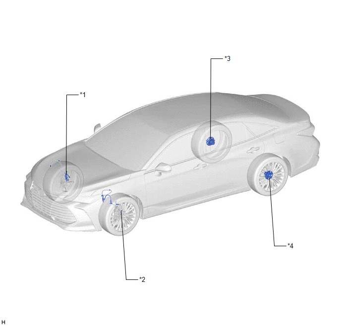
PARTS LOCATION
ILLUSTRATION
|
*1 | FRONT SPEED SENSOR RH |
*2 | FRONT SPEED SENSOR LH |
|
*3 | REAR AXLE HUB AND BEARING ASSEMBLY RH - REAR SPEED SENSOR RH |
*4 | REAR AXLE HUB AND BEARING ASSEMBLY LH - REAR SPEED SENSOR LH |
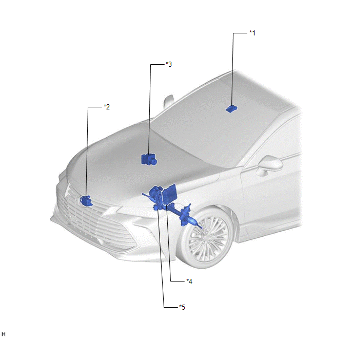
ILLUSTRATION
|
*1 | FORWARD RECOGNITION CAMERA |
*2 | MILLIMETER WAVE RADAR SENSOR ASSEMBLY |
|
*3 | BRAKE ACTUATOR ASSEMBLY - SKID CONTROL ECU |
*4 | ECM |
|
*5 | RACK AND PINION POWER STEERING GEAR ASSEMBLY - POWER STEERING ECU |
- | - |
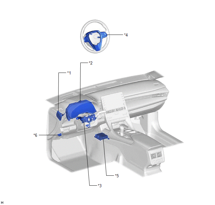
ILLUSTRATION
|
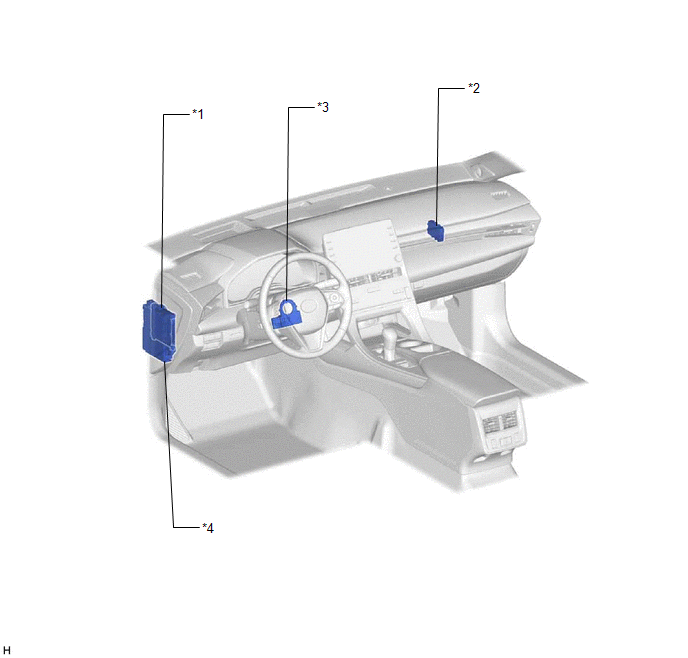
*1 | DRIVING SUPPORT ECU ASSEMBLY |
*2 | COMBINATION METER ASSEMBLY - MULTI-INFORMATION DISPLAY - LANE DEPARTURE ALERT INDICATOR - LANE DEPARTURE ALERT BUZZER |
|
*3 | TURN SIGNAL SWITCH |
*4 | STEERING PAD SWITCH ASSEMBLY - LANE DEPARTURE ALERT MAIN SWITCH - FUNCTION SWITCH (CUSTOMIZE SWITCH) |
|
*5 | AIRBAG ECU ASSEMBLY - YAW RATE SENSOR | *6 |
DLC3 |
ILLUSTRATION
|
*1 | MAIN BODY ECU (MULTIPLEX NETWORK BODY ECU) |
*2 | CENTRAL GATEWAY ECU (NETWORK GATEWAY ECU) |
|
*3 | STEERING SENSOR |
*4 | INSTRUMENT PANEL JUNCTION BLOCK ASSEMBLY - ECU-IG1 NO. 3 FUSE |
PRECAUTION
PRECAUTION FOR DISCONNECTING CABLE FROM NEGATIVE BATTERY TERMINAL
NOTICE:
|
System Name |
See Procedure |
|---|---|
|
Lane Departure Alert System (w/ Steering Control) |
|
|
Pre-collision System |
|
|
Intelligent Clearance Sonar System |
|
|
Lighting System (w/ Cornering Light) |
|
|
Parking Assist Monitor System |
|
|
Panoramic View Monitor System |
Click here 
HANDLING PRECAUTION FOR LANE DEPARTURE ALERT SYSTEM (w/ Steering Control)
(a) Keep in mind the following points when inspecting the lane departure alert system (w/ steering control).
(b) The lane departure alert system (w/ steering control) may not operate in any of the following conditions:
HANDLING PRECAUTIONS FOR CAN COMMUNICATION SYSTEM
(a) First check the CAN communication system by following How to Proceed with Troubleshooting. After checking that there are no malfunctions in the CAN communication system, proceed with troubleshooting.
Click here
HANDLING PRECAUTIONS FOR AIRBAG SYSTEM
(a) The vehicle is equipped with a Supplemental Restraint System (SRS) which includes components such as airbags. Before servicing (including removal or installation of parts), be sure to read the precaution for Supplemental Restraint System.
Click here
TROUBLESHOOTING PRECAUTIONS
(a) If a terminal contact point malfunction or part installation problem occurs, removal and reinstallation of the suspected part may return the system to normal. However, be aware that the normal condition may only be temporary.
(b) Before disconnecting connectors or removing/installing parts, determine the malfunctioning area by checking and writing down the vehicle condition at the time the malfunction occurred (DTC outputs etc.).
(c) Be sure to check for DTCs related to other systems. The lane departure alert system (w/ steering control) may be influenced by malfunctions in other systems.
HANDLING PRECAUTIONS
(a) When removing and installing ECUs, sensors, switches or other lane departure alert system (w/ steering control) related parts, perform the following:
REPLACEMENT PRECAUTIONS
(a) DRIVING SUPPORT ECU ASSEMBLY:
(1) When replacing the driving support ECU assembly, always replace it with a new one. If a driving support ECU assembly which was installed to another vehicle is used, the information stored in it will not match the information from the vehicle and a DTC may be stored.
(b) MILLIMETER WAVE RADAR SENSOR ASSEMBLY:
(1) When replacing the millimeter wave radar sensor assembly, always replace it with a new one. When a new millimeter wave radar sensor assembly is installed to the vehicle, it receives vehicle information from the driving support ECU assembly and stores it. If a millimeter wave radar sensor assembly which was installed to another vehicle is used, the information stored in the driving support ECU assembly and millimeter wave radar sensor assembly will not match and a DTC may be stored.
(2) When the millimeter wave radar sensor assembly is replaced with a new one, adjustment of the radar sensor beam axis must be performed.
Click here
(c) FORWARD RECOGNITION CAMERA:
(1) If the forward recognition camera has been replaced with a new one or the windshield glass has been removed and installed, it is necessary to perform forward recognition camera adjustment. If the system is turned on without performing forward recognition camera adjustment, DTC C1AA9 will be stored.
Click here
(2) When replacing the forward recognition camera, replace it with a new one. If a forward recognition camera which was installed to another vehicle is used, the information stored in the forward recognition camera will not match the information from the vehicle and a DTC may be stored.
(3) When replacing the forward recognition camera, do not damage the camera lens or allow it to become contaminated with foreign matter.
(4) Do not reuse a forward recognition camera that has been dropped or subjected to a strong impact.
(d) WINDSHIELD GLASS:
(1) When replacing the windshield glass of a vehicle equipped with a forward recognition camera, make sure to use a Toyota genuine part. If a non-Toyota genuine part is used, the forward recognition camera may not be able to be installed due to a missing bracket or the lane departure alert system (w/ steering control) may not operate properly due to a difference in the transmissivity or black ceramic border.
(2) Do not attach stickers, including transparent stickers, or other items to the outer side of the windshield glass within the area in front of the forward recognition camera.
PROBLEM SYMPTOMS TABLE
HINT:
|
Symptom | Suspected Area |
Link |
|---|---|---|
|
Lane departure alert system (w/ steering control) does not operate |
Steering pad switch circuit |
|
|
CAN communication system |
| |
|
Driving support ECU assembly |
| |
|
Forward recognition camera |
| |
|
The lane departure alert indicator does not illuminate even when the lane departure alert main switch is operated. |
Indicator circuit |
|
|
Steering pad switch circuit |
| |
|
CAN communication system |
| |
|
Combination meter assembly |
| |
|
Forward recognition camera |
| |
|
Driving support ECU assembly |
| |
|
The lane departure alert indicator does not turn off even when the lane departure alert main switch is operated. |
Indicator circuit |
|
|
Steering pad switch circuit |
| |
|
CAN communication system |
| |
|
Combination meter assembly |
| |
|
Driving support ECU assembly |
| |
|
Forward recognition camera |
| |
|
Lane departure alert system (w/ steering control) is not canceled even when turn signal light switch is operated |
Data List/Active Test (Check turn signal switch signal) |
|
|
Turn signal switch circuit (w/ Cornering Light) |
| |
|
Turn signal switch circuit (w/o Cornering Light) |
| |
|
Forward recognition camera |
| |
|
Increase in cases that driver can see lane markers but system cannot detect lane markers |
Windshield glass is dirty |
- |
| Forward recognition camera is dirty |
- | |
| Headlight assemblies are dirty or worn |
- | |
| Non-standard suspension is installed |
- | |
| Non-standard tires are installed |
- | |
| Non-Toyota genuine windshield glass is installed |
- | |
| There is a foreign object or foreign matter between the windshield glass and forward recognition camera |
- | |
| A sticker or similar item is attached to the area in front of the forward recognition camera |
- | |
| Adjust forward recognition camera |
| |
|
Forward recognition camera |
| |
|
Lane departure alert system (w/ steering control) is operating, but no operation condition is displayed on multi-information display in combination meter assembly | Data List/Active Test (Check the item LDA Control) |
|
|
Combination meter assembly |
| |
|
Forward recognition camera |
| |
|
Buzzer does not sound even when vehicle deviates from its lane. |
Combination meter assembly |
|
|
Forward recognition camera |
|
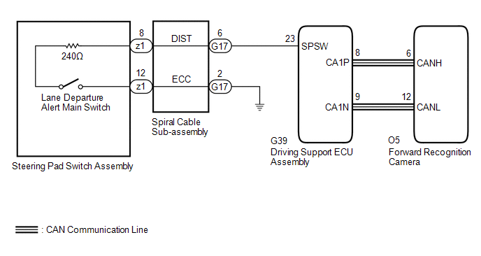
DESCRIPTION
The driving support ECU assembly receives a lane departure alert switch signal from the steering pad switch assembly and sends the signal to the forward recognition camera via CAN communication.
WIRING DIAGRAM
CAUTION / NOTICE / HINT
NOTICE:
The vehicle is equipped with a Supplemental Restraint System (SRS) which includes components such as airbags. Before servicing (including removal or installation of parts), be sure to read the precaution for Supplemental Restraint System.
Click here 
PROCEDURE
| 1. |
READ VALUE USING TECHSTREAM (CAN BUS CHECK) |
(a) Connect the Techstream to the DLC3.
(b) Turn the engine switch on (IG).
(c) Turn the Techstream on.
(d) Enter the following menus: System Select / Can Bus Check.
Click here
|
Result | Proceed to |
|---|---|
|
All of the ECUs and sensors that are currently connected to the CAN communication system are displayed |
A |
| None of the ECUs and sensors that are currently connected to the CAN communication system are displayed, or some of them are not displayed |
B |
| B |
 | GO TO CAN COMMUNICATION SYSTEM |
|
| 2. |
CHECK FOR DTCs (HEALTH CHECK) |
(a) Connect the Techstream to the DLC3.
(b) Turn the engine switch on (IG).
(c) Turn the Techstream on.
(d) Enter the following menus: System Select / Health Check.
(e) Check DTCs.
(f) Turn the engine switch off.
|
Result | Proceed to |
|---|---|
|
No DTCs are output. | A |
|
DTCs are output. | B |
| B |
| GO TO DTC CHART |
|
| 3. |
INSPECT STEERING PAD SWITCH ASSEMBLY |
(a) Remove the steering pad switch assembly.
Click here
(b) Inspect the steering pad switch assembly.
Click here
| NG | | REPLACE STEERING PAD SWITCH ASSEMBLY |
|
| 4. |
INSPECT SPIRAL CABLE SUB-ASSEMBLY |
(a) Remove the spiral cable sub-assembly.
Click here
(b) Inspect the spiral cable sub-assembly.
Click here
| NG | | REPLACE SPIRAL CABLE SUB-ASSEMBLY |
|
| 5. |
CHECK HARNESS AND CONNECTOR (SPIRAL CABLE SUB-ASSEMBLY - DRIVING SUPPORT ECU ASSEMBLY) |
(a) Disconnect the G17 spiral cable sub-assembly connector.
(b) Disconnect the G39 driving support ECU assembly connector.
(c) Measure the resistance according to the value(s) in the table below.
Standard Resistance (Check for Open):
|
Tester Connection | Condition |
Specified Condition |
|---|---|---|
|
G17-6 (DIST) - G39-23 (SPSW) |
Always | Below 1 Ω |
|
G17-2 (ECC) - Body ground |
Always | Below 1 Ω |
Standard Resistance (Check for Short):
|
Tester Connection | Condition |
Specified Condition |
|---|---|---|
|
G17-6 (DIST) or G39-23 (SPSW) - Body ground |
Always | 10 kΩ or higher |
(d) Connect the G39 driving support ECU assembly connector.
(e) Connect the G17 spiral cable sub-assembly connector.
| OK | | PROCEED TO NEXT SUSPECTED AREA SHOWN IN PROBLEM SYMPTOMS TABLE |
| NG | | REPAIR OR REPLACE HARNESS OR CONNECTOR |
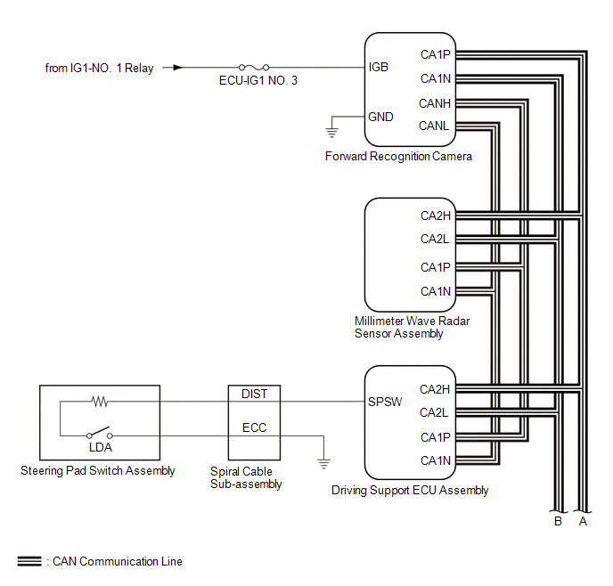
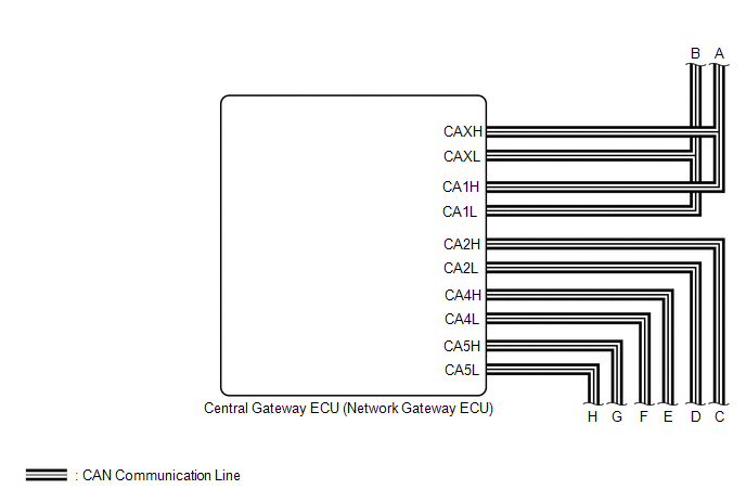
SYSTEM DIAGRAM
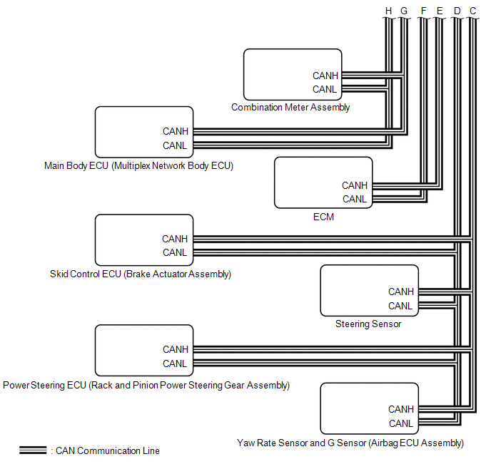
TERMINALS OF ECU
NOTICE:

CHECK FORWARD RECOGNITION CAMERA
(a) Measure the voltage and resistance according to the value(s) in the table below.
|
Terminal No. (Symbol) | Wiring Color |
Terminal Description | Condition |
Specified Condition |
|---|---|---|---|---|
|
O5-7 (IGB) - O5-10 (GND) |
LA-P - LA |
Power source | Engine switch on (IG) |
11 to 14 V |
|
Engine switch off | Below 1 V | |||
|
O5-10 (GND) - Body ground |
LA - Body ground | Ground |
Always | Below 1 Ω |
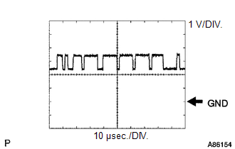
(b) Check for pulses according to the value(s) in the table below.
HINT:
If the waveform is not similar to that shown in the illustration, a malfunction of a CAN bus line, terminating resistor, or the forward recognition camera is suspected.
|
Terminal No. (Symbol) | Wiring Color |
Terminal Description | Condition |
Specified Condition |
|---|---|---|---|---|
|
O5-5 (CA1P) - O5-10 (GND) |
L - LA | CAN communication signal |
Engine switch on (IG) |
Pulse generation (See waveform 1) |
|
O5-11 (CA1N) - O5-10 (GND) |
W - LA | CAN communication signal |
Engine switch on (IG) |
Pulse generation (See waveform 2) |
|
O5-6 (CANH) - O5-10 (GND) |
G - LA | CAN communication signal |
Engine switch on (IG) |
Pulse generation (See waveform 1) |
|
O5-12 (CANL) - O5-10 (GND) |
W - LA | CAN communication signal |
Engine switch on (IG) |
Pulse generation (See waveform 2) |
(1) WAVEFORM 1
|
Item | Content |
|---|---|
|
Terminal Name | Between O5-5 (CA1P) and O5-10 (GND) Between O5-6 (CANH) and O5-10 (GND) |
|
Tester Range | 1 V/DIV., 10 μsec./DIV. |
|
Condition | Engine switch on (IG) |
HINT:
The waveform varies depending on the CAN communication signal.
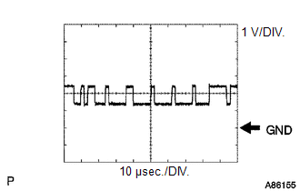
(2) WAVEFORM 2
|
Item | Content |
|---|---|
|
Terminal Name | Between O5-11 (CA1N) and O5-10 (GND) Between O5-12 (CANL) and O5-10 (GND) |
|
Tester Range | 1 V/DIV., 10 μsec./DIV. |
|
Condition | Engine switch on (IG) |
HINT:
The waveform varies depending on the CAN communication signal.

CHECK DRIVING SUPPORT ECU ASSEMBLY
(a) Measure the voltage and resistance according to the value(s) in the table below.
|
Terminal No. (Symbol) | Wiring Color |
Terminal Description | Condition |
Specified Condition |
|---|---|---|---|---|
|
G39-7 (B) - G39-28 (GND) |
B - W-B | Power source |
Engine switch on (IG) |
11 to 14 V |
|
Engine switch off | Below 1 V | |||
|
G39-23 (SPSW) - G39-28 (GND) |
R - W-B | Steering pad switch signal (Lane departure alert main switch signal) |
Engine switch off Lane departure alert main switch off |
1 MΩ or higher |
|
Engine switch off Lane departure alert main switch on |
228 to 252 Ω | |||
|
G39-28 (GND) - Body ground |
W-B - Body ground | Ground |
Always | Below 1 Ω |
(b) Check for pulses according to the value(s) in the table below.
HINT:
If the waveform is not similar to that shown in the illustration, a malfunction of a CAN bus line, terminating resistor, or the driving support ECU assembly is suspected.
|
Terminal No. (Symbol) | Wiring Color |
Terminal Description | Condition |
Specified Condition |
|---|---|---|---|---|
|
G39-8 (CA1P) - G39-28 (GND) |
G - W-B | CAN communication signal |
Engine switch on (IG) |
Pulse generation (See waveform 1) |
|
G39-9 (CA1N) - G39-28 (GND) |
W - W-B | CAN communication signal |
Engine switch on (IG) |
Pulse generation (See waveform 2) |
|
G39-10 (CA2H) - G39-28 (GND) |
R - W-B | CAN communication signal |
Engine switch on (IG) |
Pulse generation (See waveform 1) |
|
G39-11 (CA2L) - G39-28 (GND) |
W - W-B | CAN communication signal |
Engine switch on (IG) |
Pulse generation (See waveform 2) |
(1) WAVEFORM 1
|
Item | Content |
|---|---|
|
Terminal Name | Between G39-8 (CA1P) - G39-28 (GND) Between G39-10 (CA2H) - G39-28 (GND) |
|
Tester Range | 1 V/DIV., 10 μsec./DIV. |
|
Condition | Engine switch on (IG) |
HINT:
The waveform varies depending on the CAN communication signal.
(2) WAVEFORM 2
|
Item | Content |
|---|---|
|
Terminal Name | Between G39-9 (CA1N) - G39-28 (GND) Between G39-11 (CA2L) - G39-28 (GND) |
|
Tester Range | 1 V/DIV., 10 μsec./DIV. |
|
Condition | Engine switch on (IG) |
HINT:
The waveform varies depending on the CAN communication signal.
DESCRIPTION
When a communication error between the forward recognition camera and the power steering ECU (rack and pinion power steering gear assembly) is detected, the forward recognition camera notifies other ECUs and DTC U023A is stored.
|
DTC No. | Detection Item |
DTC Detection Condition | Trouble Area |
|---|---|---|---|
|
U023A | Lost Communication with Front Camera Module |
When the engine switch is on for 2 seconds or more, a communication malfunction between the forward recognition camera and the power steering ECU (rack and pinion power steering gear assembly) is detected for 5 seconds or more. |
|
CAUTION / NOTICE / HINT
NOTICE:
Click here 
Click here
PROCEDURE
|
1. | CHECK FOR DTCs |
HINT:
If DTC U023A is stored, the power steering system may be malfunctioning. Check for DTCs related to the power steering system first.
(a) Check for DTCs.
Chassis > EMPS > Trouble Codes|
Result | Proceed to |
|---|---|
|
Power steering system DTCs are not output |
A |
| Power steering system DTCs are output |
B |
| B |
 | GO TO POWER STEERING SYSTEM |
|
| 2. |
CHECK FOR DTCs |
(a) Clear the DTCs.
Chassis > LKA/LDA > Clear DTCs(b) Make sure that the DTC detection conditions are met.
HINT:
If the detection conditions are not met, the system cannot detect the malfunction.
(c) Check for DTCs.
Chassis > LKA/LDA > Trouble Codes|
Result | Proceed to |
|---|---|
|
DTC U023A is not output |
A |
| DTC U023A is output |
B |
| A |
| USE SIMULATION METHOD TO CHECK |
| B |
| REPLACE FORWARD RECOGNITION CAMERA |
DESCRIPTION
The forward recognition camera communicates with the millimeter wave radar sensor assembly via CAN communication. If there is a communication error with the millimeter wave radar sensor assembly, the forward recognition camera stores DTC U0235.
|
DTC No. | Detection Item |
DTC Detection Condition | Trouble Area |
|---|---|---|---|
|
U0235 | Lost Communication with Cruise Control Front Distance Range Sensor |
2 seconds after the engine switch is turned on (IG), a communication error between the millimeter wave radar sensor assembly and the forward recognition camera is detected for approximately 5 seconds. |
Front camera system |
PROCEDURE
| 1. |
GO TO FRONT CAMERA SYSTEM (U0235) |
HINT:
If DTC U0235 is output by the lane departure alert system (w/ steering control), perform troubleshooting for the front camera system.
Click here

| NEXT |  |
END |
DESCRIPTION
The forward recognition camera communicates with the driving support ECU assembly via CAN communication. If there is a communication error with the driving support ECU assembly, the forward recognition camera store DTC U1104.
|
DTC No. | Detection Item |
DTC Detection Condition | Trouble Area |
|---|---|---|---|
|
U1104 | Lost Communication with Driving Support ECU |
2 seconds after the engine switch is turned on (IG), a communication error between the driving support ECU assembly and the forward recognition camera is detected for approximately 5 seconds. |
Front camera system |
PROCEDURE
| 1. |
GO TO FRONT CAMERA SYSTEM (U1104) |
HINT:
If DTC U1104 is output by the lane departure alert system (w/ steering control), perform troubleshooting for the front camera system.
Click here

| NEXT |  |
END |
Toyota Avalon (XX50) 2019-2022 Service & Repair Manual > Automatic Transaxle System: Transmission Fluid Temperature Sensor "A" Circuit Short To Ground (P071011). Transmission Fluid Temperature Sensor "A" Circuit Short to Battery or Open (P071015). Input/Turbine Speed Sensor "A" Circui
Transmission Fluid Temperature Sensor "A" Circuit Short To Ground (P071011) DESCRIPTION The ATF temperature sensor converts the automatic transaxle fluid (ATF) temperature into a resistance value for use by the ECM. The ECM applies voltage to the temperature sensor through terminal THO1 of the ECM. ...


