COMPONENTS
ILLUSTRATION
|
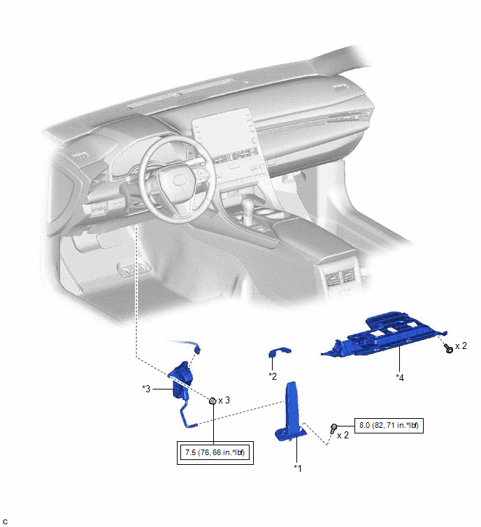
*1 | ACCELERATOR PEDAL |
*2 | ACCELERATOR PEDAL PAD |
|
*3 | ACCELERATOR PEDAL SENSOR ASSEMBLY |
*4 | NO. 1 INSTRUMENT PANEL UNDER COVER SUB-ASSEMBLY |
 |
Tightening torque for "Major areas involving basic vehicle performance such as moving/turning/stopping": N*m (kgf*cm, ft.*lbf) |
 |
N*m (kgf*cm, ft.*lbf): Specified torque |
INSTALLATION
PROCEDURE
1. INSTALL ACCELERATOR PEDAL
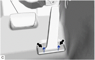
| (a) Engage the claw to install the accelerator pedal. |
|
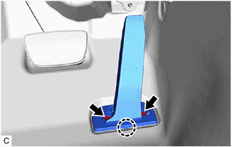
(b) Install the 2 bolts.
Torque:
8.0 N·m {82 kgf·cm, 71 in·lbf}
2. INSTALL ACCELERATOR PEDAL PAD
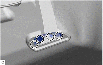
(a) Engage the 4 claws to install the accelerator pedal pad to the accelerator pedal.
3. INSTALL ACCELERATOR PEDAL SENSOR ASSEMBLY
NOTICE:
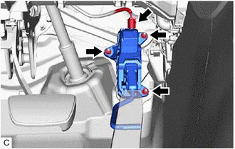
(a) Connect the rod of the accelerator pedal sensor assembly to the accelerator pedal and install the accelerator pedal sensor assembly with the 3 nuts.
Torque:
7.5 N·m {76 kgf·cm, 66 in·lbf}
(b) Connect the accelerator pedal sensor assembly connector.
4. INSTALL NO. 1 INSTRUMENT PANEL UNDER COVER SUB-ASSEMBLY
Click here 
ON-VEHICLE INSPECTION
PROCEDURE
1. INSPECT ACCELERATOR PEDAL SENSOR ASSEMBLY
(a) Connect the Techstream to the DLC3.
(b) Turn the power switch on (IG).
(c) Turn the Techstream on.
(d) Enter the following menus: Powertrain / Hybrid Control / Data List / Accelerator Position Sensor No.1 Voltage %, Accelerator Position Sensor No.2 Voltage %.
Powertrain > Hybrid Control > Data List|
Tester Display |
|---|
| Accelerator Position Sensor No.1 Voltage % |
|
Accelerator Position Sensor No.2 Voltage % |
(e) Read the Data List.
|
Tester Display | Accelerator Pedal Condition |
Specified Condition |
|---|---|---|
|
Accelerator Position Sensor No.1 Voltage % |
Not depressed | 10 to 22% |
|
Fully depressed | 52 to 90% | |
|
Not depressed → Fully depressed → Not depressed (Accelerator pedal should be operated slowly) |
Value changes progressively | |
|
Accelerator Position Sensor No.2 Voltage % |
Not depressed | 24 to 40% |
|
Fully depressed | 68 to 99% | |
|
Not depressed → Fully depressed → Not depressed (Accelerator pedal should be operated slowly) |
Value changes progressively |
REMOVAL
PROCEDURE
1. REMOVE NO. 1 INSTRUMENT PANEL UNDER COVER SUB-ASSEMBLY
Click here 
2. REMOVE ACCELERATOR PEDAL SENSOR ASSEMBLY
NOTICE:
| (a) Disconnect the accelerator pedal sensor assembly connector. |
|
(b) Remove the 3 nuts and disconnect the rod of the accelerator pedal sensor assembly from the accelerator pedal to remove the accelerator pedal sensor assembly.
NOTICE:
If the accelerator pedal sensor assembly has been struck or dropped, replace it.
3. REMOVE ACCELERATOR PEDAL PAD
| (a) Disengage the 4 claws and remove the accelerator pedal pad from the accelerator pedal. |
|
4. REMOVE ACCELERATOR PEDAL
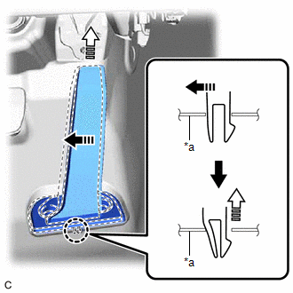
| (a) Remove the 2 bolts. |
|
(b) Push the accelerator pedal in the direction indicated by the arrow (1) shown in the illustration to disengage the claw.
|
*a | Vehicle Body |
 |
Remove in this Direction (1) |
 |
Remove in this Direction (2) |
(c) Pull the accelerator pedal in the direction indicated by the arrow (2) shown in the illustration to remove it.
Toyota Avalon (XX50) 2019-2022 Service & Repair Manual > Meter / Gauge System(for Hv Model): Lost Communication With ECM/PCM "A" Missing Message (U010087,...,U113387). Vehicle Proximity Notification System Warning Message Display Malfunction
Lost Communication With ECM/PCM "A" Missing Message (U010087,...,U113387) DESCRIPTION The combination meter assembly communicates with each ECU via CAN communication. DTC No. Detection Item DTC Detection Condition Trouble Area Memory Note U010087 Lost Communication With ECM/PCM "A" Missing Message D ...