COMPONENTS
ILLUSTRATION
|
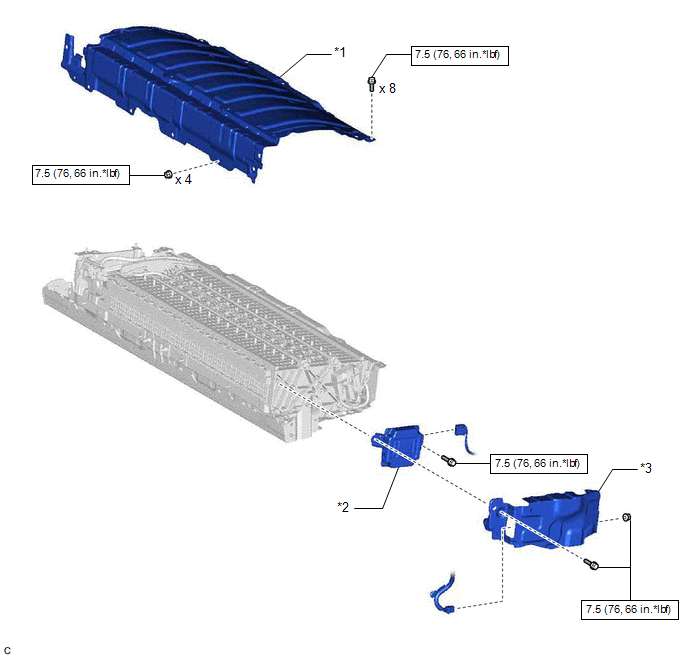
*1 | UPPER HV BATTERY COVER SUB-ASSEMBLY |
*2 | BATTERY VOLTAGE SENSOR |
|
*3 | NO. 1 HV BATTERY SHIELD PANEL |
- | - |
 |
N*m (kgf*cm, ft.*lbf): Specified torque |
- | - |
INSTALLATION
PROCEDURE
1. INSTALL BATTERY VOLTAGE SENSOR
CAUTION:
Be sure to wear insulated gloves and protective goggles.
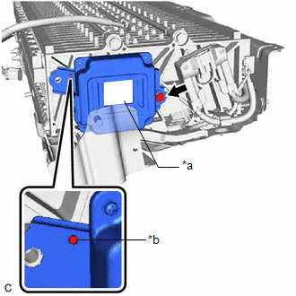
| (a) Install the battery voltage sensor to the HV battery with the bolt. Torque: 7.5 N·m {76 kgf·cm, 66 in·lbf} NOTICE:
|
|
(b) Connect the battery voltage sensor connector.
NOTICE:
Make sure that the connector is connected securely.
2. INSTALL NO. 1 HV BATTERY SHIELD PANEL
CAUTION:
Be sure to wear insulated gloves and protective goggles.
(a) Pull back the rear No. 1 HV battery shield and install the No. 1 HV battery shield panel to the HV battery.
(b) Install the bolt and nut.
Torque:
7.5 N·m {76 kgf·cm, 66 in·lbf}
(c) Connect the battery voltage sensor connector.
(d) Engage the clamp.
3. INSTALL UPPER HV BATTERY COVER SUB-ASSEMBLY
CAUTION:
Be sure to wear insulated gloves and protective goggles.
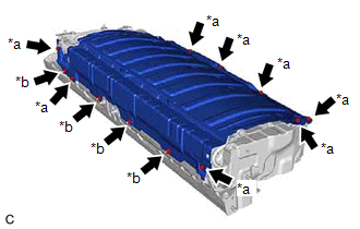
(a) Install the upper HV battery cover sub-assembly to the HV battery with the 8 bolts and 4 nuts.
Torque:
7.5 N·m {76 kgf·cm, 66 in·lbf}
4. INSTALL HV BATTERY
Click here 
REMOVAL
CAUTION / NOTICE / HINT
The necessary procedures (adjustment, calibration, initialization or registration) that must be performed after parts are removed and installed, or replaced during battery voltage sensor removal/installation are shown below.
Necessary Procedures After Parts Removed/Installed/Replaced|
Replaced Part or Performed Procedure |
Necessary Procedure | Effect/Inoperative Function when Necessary Procedures not Performed |
Link |
|---|---|---|---|
|
*1: When performing learning using the Techstream.
Click here | |||
|
Auxiliary battery terminal is disconnected/reconnected |
Perform steering sensor zero point calibration |
Lane departure alert system (w/ Steering Control) |
|
|
Pre-collision system | |||
| Intelligent clearance sonar system* | |||
|
Lighting System (for HV Model with Cornering Light) | |||
|
Memorize steering angle neutral point |
Parking assist monitor system |
| |
|
Panoramic view monitor system |
| ||
|
Replacement of HV battery |
Battery status info update |
HV battery status information cannot be updated |
|
CAUTION:
Click here 
NOTICE:
Click here
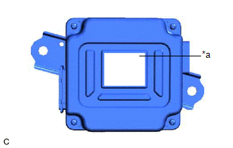
|
*a |
Blue Label |
PROCEDURE
1. REMOVE HV BATTERY
Click here
2. REMOVE UPPER HV BATTERY COVER SUB-ASSEMBLY
CAUTION:
Be sure to wear insulated gloves and protective goggles.
| (a) Remove the 8 bolts, 4 nuts and upper HV battery cover sub-assembly from the HV battery. |
|
3. REMOVE NO. 1 HV BATTERY SHIELD PANEL
CAUTION:
Be sure to wear insulated gloves and protective goggles.
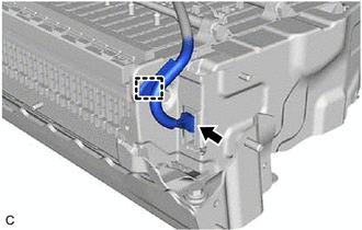
| (a) Disengage the clamp. |
|
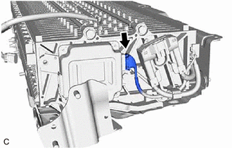
(b) Disconnect the battery voltage sensor connector.
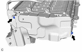
| (c) Remove the bolt and nut. |
|
(d) Pull back the rear No. 1 HV battery shield and remove the No. 1 HV battery shield panel from the HV battery.
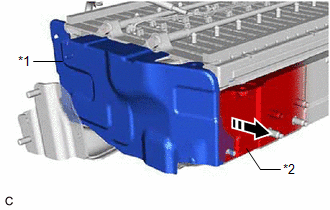
|
*1 | No. 1 HV Battery Shield Panel |
|
*2 | Rear No. 1 HV Battery Shield |
 |
Pull Back |
4. REMOVE BATTERY VOLTAGE SENSOR
CAUTION:
Be sure to wear insulated gloves and protective goggles.
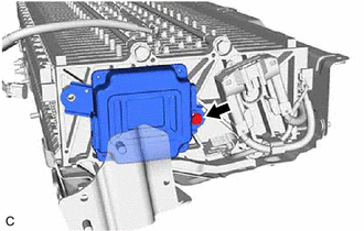
| (a) Disconnect the battery voltage sensor connector. NOTICE: Insulate each disconnected high-voltage connector with insulating tape. Wrap the connector from the wire harness side to the end of the connector. |
|
| (b) Remove the bolt and battery voltage sensor from the HV battery. NOTICE: If the battery voltage sensor has been struck or dropped, replace it. |
|
Toyota Avalon (XX50) 2019-2022 Service & Repair Manual > Hybrid Control System: Hybrid/EV Battery "A" Voltage Sensor/Boosting Converter Voltage Sensor "A" Signal Compare Failure (P1C2D62)
DTC SUMMARY MALFUNCTION DESCRIPTION The hybrid vehicle control ECU detects a VB sensor or VL sensor malfunction. The cause of this malfunction may be one of the following: Inverter voltage (VB or VL) sensor internal circuit malfunction Voltage sensor malfunction Motor generator control ECU (MG ECU) ...