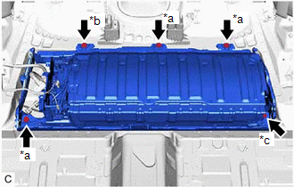
INSTALLATION PROCEDURE 1. INSTALL NO. 1 HV BATTERY INTAKE DUCT LH Click here 2. INSTALL NO. 2 HYBRID BATTERY SHIELD SUB-ASSEMBLY Click here 3. INSTALL HV BATTERY JUNCTION BLOCK ASSEMBLY Click here 4. INSTALL HYBRID BATTERY TERMINAL BLOCK Click here 5. INSTALL BATTERY VOLTAGE SENSOR Click here 6. INSTALL NO. 1 HV BATTERY SHIELD PANEL Click here 7. INSTALL UPPER HV BATTERY COVER SUB-ASSEMBLY Click here 8. TEMPORARILY INSTALL NO. 4 HV BATTERY END PLATE SUB-ASSEMBLY CAUTION: Be sure to wear insulated gloves. (a) Temporarily install the No. 4 HV battery end plate sub-assembly to the HV battery with the 2 bolts and 2 nuts. (b) Fully tighten the 2 nuts. Torque: 19 N·m {194 kgf·cm, 14 ft·lbf} 9. INSTALL NO. 5 HV BATTERY END PLATE SUB-ASSEMBLY CAUTION: Be sure to wear insulated gloves. (a) Install the No. 5 HV battery end plate sub-assembly to the HV battery with the 12 nuts. Torque: 19 N·m {194 kgf·cm, 14 ft·lbf} 10. INSTALL NO. 4 HV BATTERY SHIELD SUB-ASSEMBLY CAUTION: Be sure to wear insulated gloves. (a) Install the No. 4 HV battery shield sub-assembly to the HV battery with the 4 nuts. Torque: 19 N·m {194 kgf·cm, 14 ft·lbf} 11. INSTALL NO. 3 HV BATTERY SHIELD SUB-ASSEMBLY CAUTION: Be sure to wear insulated gloves. (a) Install the No. 3 HV battery shield sub-assembly to the HV battery with the 4 nuts. Torque: 19 N·m {194 kgf·cm, 14 ft·lbf} 12. INSTALL NO. 4 HV BATTERY END PLATE SUB-ASSEMBLY CAUTION: Be sure to wear insulated gloves. (a) Fully tighten the 2 bolts. Torque: 19 N·m {194 kgf·cm, 14 ft·lbf} 13. INSTALL HV BATTERY CAUTION: Be sure to wear insulated gloves.
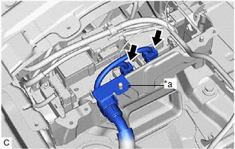
14. CONNECT FLOOR WIRE CAUTION: Be sure to wear insulated gloves. (a) Connect the battery voltage sensor connector. (b) Engage the clamp. 15. INSTALL NO. 1 HYBRID BATTERY EXHAUST DUCT CAUTION: Be sure to wear insulated gloves. (a) Engage the claw to install the No. 1 hybrid battery exhaust duct to the HV battery. (b) Install the clip. 16. CONNECT FLOOR WIRE CAUTION: Be sure to wear insulated gloves. (a) Engage the 2 clamps. 17. INSTALL NO. 1 INDOOR ELECTRICAL KEY ANTENNA ASSEMBLY Click here 18. CONNECT FLOOR WIRE CAUTION: Be sure to wear insulated gloves. (a) Connect the HV battery junction block assembly connector. (b) Connect the electric vehicle battery plug assembly connector. (c) Engage the clamp. 19. CONNECT HV FLOOR UNDER WIRE CAUTION: Be sure to wear insulated gloves. (a) Connect the floor wire connector.
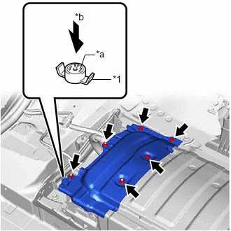
(c) Connect the 2 HV battery junction block assembly connectors. NOTICE: Make sure that the connectors are connected securely. 20. INSTALL NO. 1 HV BATTERY COVER PANEL RH CAUTION: Be sure to wear insulated gloves.
(b) Install the battery cover lock striker, then push the button to lock it. 21. INSTALL BATTERY COOLING BLOWER ASSEMBLY Click here
22. INSTALL SERVICE PLUG GRIP Click here
23. PERFORM INITIALIZATION Click here
|
Toyota Avalon (XX50) 2019-2022 Service & Repair Manual > Generator: Reassembly
REASSEMBLY PROCEDURE 1. INSTALL GENERATOR DRIVE END FRAME BEARING (a) Using SST and a press, install a new generator drive end frame bearing to the generator drive end frame. SST: 09950-60010 09951-00470 SST: 09950-70010 09951-07100 (b) Fit the tabs of the retainer plate into the cutouts of the gene ...