DTC CHECK / CLEAR
CHECK FOR DTCS
(a) Connect the Techstream to the DLC3.
(b) Turn the power switch on (IG).
(c) Turn the Techstream on.
(d) Enter the following menus: Powertrain / Hybrid Control / Trouble Codes.
Powertrain > Hybrid Control > Trouble Codes(e) Check the DTCs and freeze frame data, and then write them down.
(f) Check the details of the DTCs.
|
Display Item | Description |
|---|---|
|
Test Failed | Shows the malfunction judgment results during the current trip. |
|
Pending | Shows the malfunction judgment results up to now (Indicates the possibility of a malfunction when no DTC is confirmed.) |
|
Confirmed | Shows the DTCs confirmed up to now (The number of current trips differs for each DTC.) |
(1) Enter the following menus: Powertrain / Hybrid Control / Utility / Check Mode.
Powertrain > Hybrid Control > Utility|
Tester Display |
|---|
| Check Mode |
(2) Check items on the display and press "Next".
NOTICE:
CHECK FREEZE FRAME DATA
(a) If a DTC is present, select it in order to display its freeze frame data.
(b) Read the freeze frame data recorded when the DTC was stored.
CHECK TIME STAMP
HINT:
By checking Time Stamp, the time and order in which DTCs were stored in an ECU can be checked.
(a) Connect the Techstream to the DLC3.
(b) Turn the power switch on (IG).
(c) Turn the Techstream on.
(d) Enter the following menus: Health Check.
(e) Perform the following steps when the data setting screen is displayed.
(f) Select the systems for which to perform Health Check and check for time stamp data.
Selectable items:(g) Select "Yes" when "Do you want to store time stamp data?" is displayed.
HINT:
If "Yes" is not selected, time stamp data will not be stored.
(h) After Health Check has completed, select "Time Stamp Data" to display the Time Stamp screen.
(i) Select the desired system from the drop-down list on the bottom of the Time Stamp screen.
(j) Check the order and time which DTCs were stored for the selected system.
CHECK FOR DTCS (SYSTEMS EXCEPT HYBRID VEHICLE CONTROL ECU)
HINT:
The hybrid vehicle control ECU maintains communication with other computers, including the motor generator control ECU, the ECM, skid control ECU assembly and power steering ECU assembly. Therefore, if the hybrid vehicle control ECU outputs a warning, it is necessary to check and record the DTCs of all systems.
(a) If DTCs are present, check the relevant systems.
HINT:
If DTCs for the CAN communication system are present in addition to other DTCs, first troubleshoot and repair any malfunctions in the CAN communication system.
CLEAR DTCS
NOTICE:
Clearing the DTCs will also clear the freeze frame data.
(a) Connect the Techstream to the DLC3.
(b) Turn the power switch on (IG).
(c) Turn the Techstream on.
(d) Enter the following menus: Powertrain / Hybrid Control / Trouble Codes.
Powertrain > Hybrid Control > Trouble Codes(e) Clear DTCs and freeze frame data.
Powertrain > Hybrid Control > Clear DTCsOUTLINE
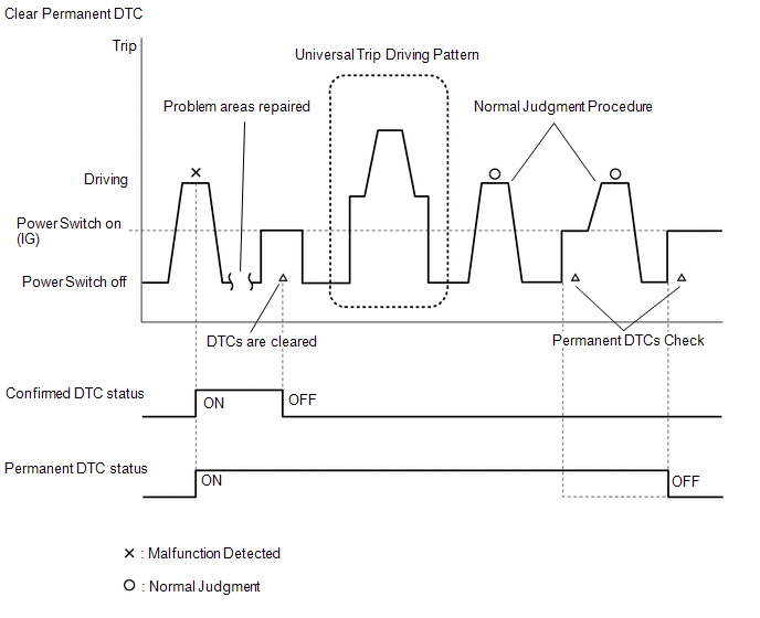
CLEAR PERMANENT DTC
(a) Connect the Techstream to the DLC3.
(b) Turn the power switch on (IG).
(c) Turn the Techstream on.
(d) Enter the following menus: Powertrain / Hybrid Control / Trouble Codes.
Powertrain > Hybrid Control > Trouble CodesHINT:
If "YES" is displayed for the value of "PERMANENT" at the top right of the Techstream screen, permanent DTCs are stored.
(e) Select the "Generic" tab.
(f) Check if permanent DTCs are stored.
HINT:
If permanent DTCs are not output, it is not necessary to continue this procedure.
(g) Clear the DTCs (even if no DTCs are stored, perform the clear DTC procedure).
Powertrain > Hybrid Control > Clear DTCsNOTICE:
Do not clear the DTCs or disconnect the cable from the auxiliary battery terminal after performing this step.
(h) Perform the universal trip.
CAUTION:
When performing the driving pattern, obey all speed limits and traffic laws.
HINT:
The universal trip driving pattern and normal judgment procedure can be performed consecutively in the same driving cycle.
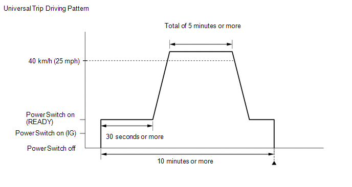
(1) Turn the power switch on (READY) and wait for 30 seconds or more.
(2) Drive the vehicle at 40 km/h (25 mph) or more for a total of 5 minutes or more.
HINT:
It is possible to complete the drive pattern even if the vehicle decelerates to less than 40 km/h (25 mph) during the driving cycle provided that the vehicle is driven at 40 km/h (25 mph) or more for a total of 5 minutes.
(3) Allow 10 minutes or more to elapse from the time the power switch turned on (READY).
(i) Turn the power switch off and wait for 2 minutes or more.
(j) Perform the normal judgment procedure in the respective confirmation driving pattern of each output DTC.
HINT:
Do not turn the power switch off by mistake during this step.
(k) With power switch on (READY) and wait for 5 seconds or more.
(l) Turn the power switch off and wait for 2 minutes or more.
(m) Turn the power switch on (IG).
(n) Enter the following menus: Powertrain / Hybrid Control / Trouble Codes.
Powertrain > Hybrid Control > Trouble Codes(o) Check that the permanent DTCs have been cleared.
HINT:
If permanent DTCs are not output, it is not necessary to continue this procedure.
(p) Perform the normal judgment procedure in the respective confirmation driving pattern of each output DTC.
HINT:
Do not turn the power switch off by mistake during this step.
(q) With power switch on (READY) and wait for 5 seconds or more.
(r) Turn the power switch off and wait for 2 minutes or more.
(s) Turn the power switch on (IG).
(t) Enter the following menus: Powertrain / Hybrid Control / Trouble Codes.
Powertrain > Hybrid Control > Trouble Codes(u) Check that the permanent DTCs have been cleared.
HINT:
Permanent DTCs will be cleared if a normal judgment is obtained during 3 consecutive driving cycles with the MIL illuminated.
DESCRIPTION
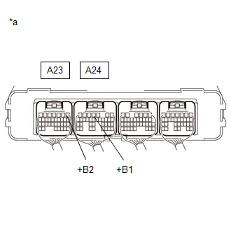
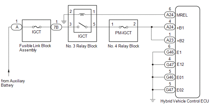
If the power switch is on (IG), the hybrid vehicle control ECU applies current to the MREL terminal to turn the IGCT relay on. This supplies power to the +B1 and +B2 terminals.
WIRING DIAGRAM
CAUTION / NOTICE / HINT
NOTICE:
After turning the power switch off, waiting time may be required before disconnecting the cable from the negative (-) auxiliary battery terminal. Therefore, make sure to read the disconnecting the cable from the negative (-) auxiliary battery terminal notices before proceeding with work.
Click here 
PROCEDURE
| 1. |
CHECK HYBRID VEHICLE CONTROL ECU (+B1, +B2 VOLTAGE) |
(a) Turn the power switch on (IG).
| (b) Measure the voltage according to the value(s) in the table below. Standard Voltage:
|
|
(c) Turn the power switch off.
| NG |  |
GO TO STEP 3 |
|
| 2. |
CHECK HARNESS AND CONNECTOR (HYBRID VEHICLE CONTROL ECU - BODY GROUND) |
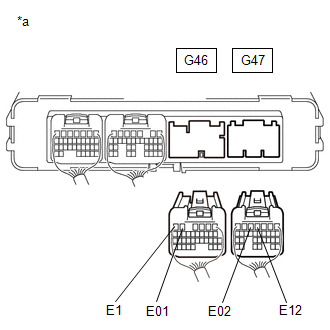
(a) Disconnect the G46 and G47 hybrid vehicle control ECU connectors.
| (b) Measure the resistance according to the value(s) in the table below. Standard Resistance:
|
|
(c) Reconnect the G46 and G47 hybrid vehicle control ECU connectors.
| OK | | GO TO PROBLEM SYMPTOMS TABLE |
| NG | | REPAIR OR REPLACE HARNESS OR CONNECTOR |
| 3. |
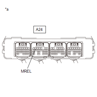
CHECK HYBRID VEHICLE CONTROL ECU (MREL VOLTAGE) |
(a) Turn the power switch on (IG).
| (b) Measure the voltage according to the value(s) in the table below. Standard Voltage:
|
|
(c) Turn the power switch off.
| NG | |
REPLACE HYBRID VEHICLE CONTROL ECU |
|
| 4. |
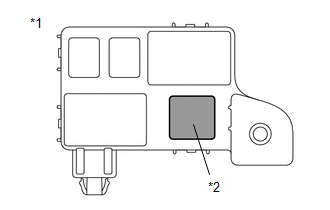
CHECK FUSE (PM-IGCT) |
| (a) Remove the PM-IGCT fuse from the No. 4 relay block. |
|
(b) Measure the resistance according to the value(s) in the table below.
Standard Resistance:
|
Tester Connection | Condition |
Specified Condition |
|---|---|---|
|
PM-IGCT fuse | Always |
Below 1 Ω |
(c) Install the PM-IGCT fuse.
| NG | | GO TO STEP 12 |
|
| 5. |
CHECK FUSIBLE LINK BLOCK ASSEMBLY (IGCT FUSE) |
(a) Disconnect the cable from the negative (-) auxiliary battery terminal.
(b) Disconnect the cable from the positive (+) auxiliary battery terminal.
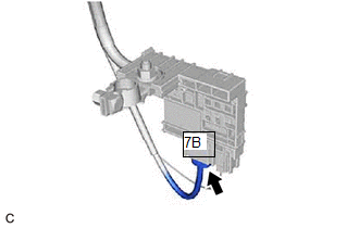
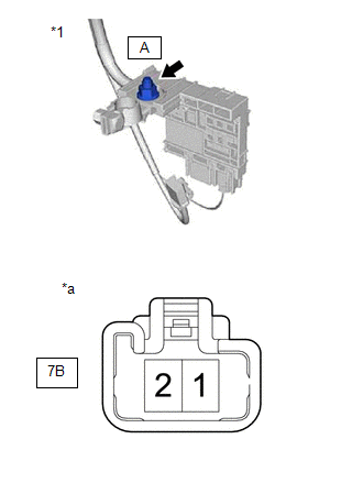
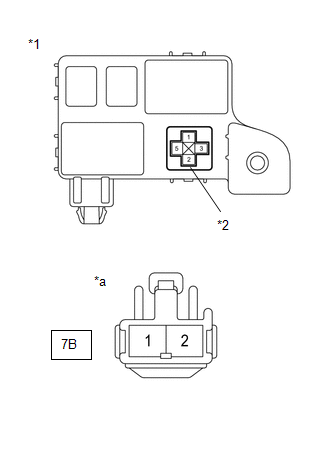
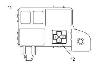
| (c) Disconnect the 7B fusible link block assembly connector. |
|
| (d) Measure the resistance according to the value(s) in the table below. Standard Resistance:
|
|
(e) Reconnect the 7B fusible link block assembly connector.
(f) Reconnect the cable to the positive (+) auxiliary battery terminal.
(g) Reconnect the cable to the negative (-) auxiliary battery terminal.
| NG | | GO TO STEP 13 |
|
| 6. |
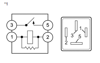
INSPECT RELAY (IGCT) |
| (a) Remove the IGCT relay from the No. 3 relay block. |
|
| (b) Measure the resistance according to the value(s) in the table below. Standard Resistance:
|
|
(c) Install the IGCT relay.
| NG | |
REPLACE RELAY (IGCT) |
|
| 7. |
CHECK HARNESS AND CONNECTOR (NO. 4 RELAY BLOCK - HYBRID VEHICLE CONTROL ECU) |
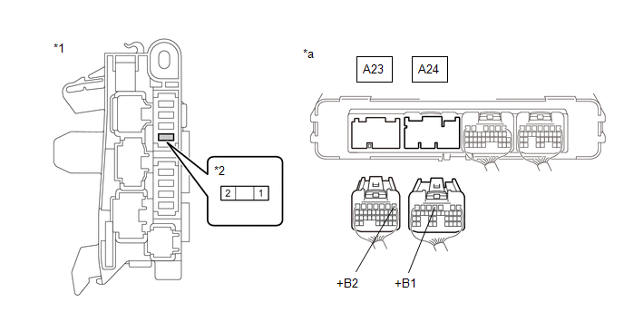
(a) Disconnect the A23 and A24 hybrid vehicle control ECU connectors.
(b) Remove the PM-IGCT fuse from the No. 4 relay block.
(c) Measure the resistance according to the value(s) in the table below.
|
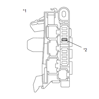
*1 | No. 4 Relay Block |
*2 | PM-IGCT Fuse Holder |
|
*a | Rear view of wire harness connector (to Hybrid Vehicle Control ECU) |
- | - |
Standard Resistance:
|
Tester Connection | Condition |
Specified Condition |
|---|---|---|
|
A24-4 (+B1) - 2 (PM-IGCT fuse holder) |
Always | Below 1 Ω |
|
A23-1 (+B2) - 2 (PM-IGCT fuse holder) |
Always | Below 1 Ω |
(d) Reconnect the A23 and A24 hybrid vehicle control ECU connectors.
(e) Install the PM-IGCT fuse.
| NG | | REPAIR OR REPLACE HARNESS OR CONNECTOR |
|
| 8. |
CHECK HARNESS AND CONNECTOR (NO. 3 RELAY BLOCK - NO. 4 RELAY BLOCK) |
(a) Remove the IGCT relay from the No. 3 relay block.
(b) Remove the PM-IGCT fuse from the No. 4 relay block.
(c) Measure the resistance according to the value(s) in the table below.
|
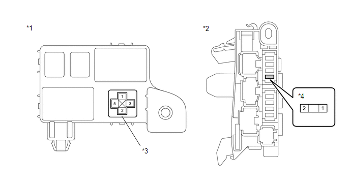
*1 | No. 3 Relay Block |
*2 | No. 4 Relay Block |
|
*3 | IGCT Relay Holder |
*4 | PM-IGCT Fuse Holder |
Standard Resistance:
|
Tester Connection | Condition |
Specified Condition |
|---|---|---|
|
5 (IGCT relay holder) - 1 (PM-IGCT fuse holder) |
Always | Below 1 Ω |
(d) Install the PM-IGCT fuse.
(e) Install the IGCT relay.
| NG | | REPAIR OR REPLACE HARNESS OR CONNECTOR |
|
| 9. |
CHECK HARNESS AND CONNECTOR (FUSIBLE LINK BLOCK ASSEMBLY - NO. 3 RELAY BLOCK) |
(a) Disconnect the 7B fusible link block assembly connector.
| (b) Remove the IGCT relay from the No. 3 relay block. |
|
(c) Measure the resistance according to the value(s) in the table below.
Standard Resistance:
|
Tester Connection | Condition |
Specified Condition |
|---|---|---|
|
3 (IGCT relay holder) - 7B-1 |
Always | Below 1 Ω |
(d) Install the IGCT relay.
(e) Reconnect the 7B fusible link block assembly connector.
| NG | | REPAIR OR REPLACE HARNESS OR CONNECTOR |
|
| 10. |
CHECK HARNESS AND CONNECTOR (HYBRID VEHICLE CONTROL ECU - NO. 3 RELAY BLOCK) |
(a) Disconnect the A24 hybrid vehicle control ECU connector.
(b) Remove the IGCT relay from the No. 3 relay block.
(c) Measure the resistance according to the value(s) in the table below.
|
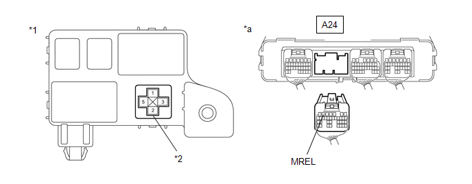
*1 | No. 3 Relay Block |
*2 | IGCT Relay Holder |
|
*a | Rear view of wire harness connector (to Hybrid Vehicle Control ECU) |
- | - |
Standard Resistance:
|
Tester Connection | Condition |
Specified Condition |
|---|---|---|
|
A24-6 (MREL) - 1 (IGCT relay holder) |
Always | Below 1 Ω |
|
A24-6 (MREL) or 1 (IGCT relay holder) - Body ground and other terminals |
Always | 10 kΩ or higher |
(d) Install the IGCT relay.
(e) Reconnect the A24 hybrid vehicle control ECU connector.
| NG | | REPAIR OR REPLACE HARNESS OR CONNECTOR |
|
| 11. |
CHECK HARNESS AND CONNECTOR (NO. 3 RELAY BLOCK - BODY GROUND) |
(a) Remove the IGCT relay from the No. 3 relay block.
| (b) Measure the resistance according to the value(s) in the table below. Standard Resistance:
|
|
(c) Install the IGCT relay.
| OK | |
CHECK FOR INTERMITTENT PROBLEMS |
| NG | | REPAIR OR REPLACE HARNESS OR CONNECTOR |
| 12. |
CHECK HARNESS AND CONNECTOR (NO. 4 RELAY BLOCK - HYBRID VEHICLE CONTROL ECU) |
(a) Remove the PM-IGCT fuse from the No. 4 relay block.
(b) Disconnect the A23 and A24 hybrid vehicle control ECU connectors.
(c) Measure the resistance according to the value(s) in the table below.
|
*1 | No. 4 Relay Block |
*2 | PM-IGCT Fuse Holder |
|
*a | Rear view of wire harness connector (to Hybrid Vehicle Control ECU) |
- | - |
Standard Resistance:
|
Tester Connection | Condition |
Specified Condition |
|---|---|---|
|
A24-4 (+B1) or 2 (PM-IGCT fuse holder) - Body ground and other terminals |
Always | 10 kΩ or higher |
|
A23-1 (+B2) or 2 (PM-IGCT fuse holder) - Body ground and other terminals |
Always | 10 kΩ or higher |
(d) Reconnect the A23 and A24 hybrid vehicle control ECU connectors.
(e) Install the PM-IGCT fuse.
| OK | | REPLACE FUSE (PM-IGCT) |
| NG | | GO TO STEP 15 |
| 13. |
CHECK HARNESS AND CONNECTOR (FUSIBLE LINK BLOCK ASSEMBLY - NO. 3 RELAY BLOCK) |
(a) Disconnect the 7B fusible link block assembly connector.
(b) Remove the IGCT relay from the No. 3 relay block.
| (c) Measure the resistance according to the value(s) in the table below. Standard Resistance:
|
|
(d) Install the IGCT relay.
(e) Reconnect the 7B fusible link block assembly connector.
| NG | | GO TO STEP 16 |
|
| 14. |
CHECK HARNESS AND CONNECTOR (NO. 3 RELAY BLOCK - NO. 4 RELAY BLOCK) |
(a) Remove the IGCT relay from the No. 3 relay block.
(b) Remove the PM-IGCT fuse from the No. 4 relay block.
(c) Measure the resistance according to the value(s) in the table below.
|
*1 | No. 3 Relay Block |
*2 | No. 4 Relay Block |
|
*3 | IGCT Relay Holder |
*4 | PM-IGCT Fuse Holder |
Standard Resistance:
|
Tester Connection | Condition |
Specified Condition |
|---|---|---|
|
5 (IGCT relay holder) or 1 (PM-IGCT fuse holder) - Body ground and other terminals |
Always | 10 kΩ or higher |
(d) Install the PM-IGCT fuse.
(e) Install the IGCT relay.
| OK | | REPLACE FUSIBLE LINK BLOCK ASSEMBLY (IGCT FUSE) |
| NG | | GO TO STEP 17 |
| 15. |
REPAIR OR REPLACE HARNESS OR CONNECTOR |
| NEXT | | REPLACE FUSE (PM-IGCT) |
| 16. |
REPAIR OR REPLACE HARNESS OR CONNECTOR |
| NEXT | | REPLACE FUSIBLE LINK BLOCK ASSEMBLY (IGCT FUSE) |
| 17. |
REPAIR OR REPLACE HARNESS OR CONNECTOR |
| NEXT | | REPLACE FUSIBLE LINK BLOCK ASSEMBLY (IGCT FUSE) |
FREEZE FRAME DATA
FREEZE FRAME DATA
HINT:
The hybrid vehicle control ECU records vehicle and driving condition information as freeze frame data the moment a DTC is stored. It can be used for estimating or duplicating the vehicle conditions that were present when the malfunction occurred.
(a) Connect the Techstream to the DLC3.
(b) Turn the power switch on (IG).
(c) Turn the Techstream on.
(d) Enter the following menus: Powertrain / Hybrid Control / Trouble Codes.
Powertrain > Hybrid Control > Trouble Codes(e) Select a DTC in order to display its freeze frame data.
(f) Check the freeze frame information recorded with the DTC.
Powertrain > Hybrid Control|
Tester Display | Measurement Item |
Range |
|---|---|---|
| Vehicle Speed |
Vehicle speed | Min.: 0 km/h (0 mph), Max.: 255 km/h (158 mph) |
|
Target Engine Power | Target engine power |
Min.: 0 W, Max.: 655350 W |
|
Execute Engine Power | Execute engine power |
Min.: 0 W, Max.: 655350 W |
|
Target Engine Revolution |
Target engine revolution |
Min.: 0 rpm, Max.: 32767 rpm |
|
Engine Speed | Engine speed |
- |
| Calculate Load |
Calculate load | Min.: 0.00%, Max.: 100.00% |
|
Coolant Temperature | Engine coolant temperature |
Min.: -40°C (-40°F), Max.: 215°C (419°F) |
|
Starter Switch Signal | Starter ON / OFF signal |
ON or OFF |
| Engine Idling Request |
Engine idling request | ON or OFF |
|
Engine Start Request (A/C) |
Engine idling request from air conditioning amplifier assembly |
ON or OFF |
| Engine Start Request (Engine Warm-up) |
Engine idling request to warm up engine |
ON or OFF |
| Engine Start Request (Hybrid Battery Charging) |
Engine idling request to charge HV battery |
ON or OFF |
| Engine Mode |
Engine status | Stop / Stop Process / Startup Process / Running |
|
Engine Run Time | Elapsed time after starting engine |
Min.: 0 sec, Max.: 65535 sec |
|
Engine Stop Request | Engine stop request |
ON or OFF |
| Engine Stop F/C Status |
Engine fuel cut status |
ON or OFF |
| Lack of Fuel |
Lack of fuel | ON or OFF |
|
Accelerator Position | Accelerator pedal depressed angle |
Min.: 0.0%, Max.: 100.0% |
|
Accelerator Pedal Status |
Accelerator pedal status |
ON or OFF |
| Accelerator Position Sensor No.1 Voltage % |
Accelerator pedal position sensor No. 1 |
Min.: 0.00%, Max.: 100.00% |
|
Accelerator Position Sensor No.2 Voltage % |
Accelerator pedal position sensor No. 2 |
Min.: 0.00%, Max.: 100.00% |
|
Throttle Position Sensor No.1 Voltage % |
Throttle valve angle | Min.: 0.00%, Max.: 100.00% |
|
Master Cylinder Control Torque |
Braking torque equivalent to master cylinder brake fluid pressure (Total braking torque) |
Min.: -4096.00 Nm, Max.: 4095.87 Nm |
|
Brake Cancel Switch | Brake pedal status |
ON or OFF |
| Shift Position |
Current shift state | P / R / N / D / B |
|
Shift Position (Meter) |
Shift position of meter display |
Not Displayed / P / R / N / D / B |
|
Shift Switch Status (N,P Position) |
Shift position status (N or P position) |
ON or OFF |
| Shift Position Sensor (PNB) |
Shift position sensor | ON or OFF |
|
Shift Position Sensor (PR) |
Shift position sensor | ON or OFF |
|
Shift Position Sensor (DB1) |
Shift position sensor | ON or OFF |
|
Shift Position Sensor (DB2) |
Shift position sensor | ON or OFF |
|
Shift Position Sensor (N) |
Shift position sensor | ON or OFF |
|
Shift Position Sensor (R) |
Shift position sensor | ON or OFF |
|
Shift Position Sensor (P) |
Shift position sensor | ON or OFF |
|
Shift Lock Release Request |
Shift lock release request |
ON or OFF |
| Sports Shift Position |
Sports shift position | Min.: 0, Max.: 255 |
|
Sports Shift UP Signal |
Sports shift UP signal |
ON or OFF |
| Sports Shift DOWN Signal |
Sports Shift DOWN Signal |
ON or OFF |
| Transaxle Oil Temperature |
Hybrid vehicle transaxle oil temperature |
Min.: -40°C (-40°F), Max.: 215°C (419°F) |
|
Transaxle Oil Temperature Sensor Voltage |
Hybrid vehicle transaxle oil temperature sensor voltage |
Min: 0.00 V, Max: 4.99 V |
|
FR Wheel Speed | Front wheel speed RH |
Min.: 0.00 km/h (0 mph), Max.: 327.67 km/h (204 mph) |
|
FL Wheel Speed | Front wheel speed LH |
Min.: 0.00 km/h (0 mph), Max.: 327.67 km/h (204 mph) |
|
RR Wheel Speed | Rear wheel speed RH |
Min.: 0.00 km/h (0 mph), Max.: 327.67 km/h (204 mph) |
|
RL Wheel Speed | Rear wheel speed LH |
Min.: 0.00 km/h (0 mph), Max.: 327.67 km/h (204 mph) |
|
Atmospheric Pressure | Atmospheric pressure |
Min.: 0 kPa, Max.: 255 kPa |
|
Intake Manifold Absolute Pressure |
Intake manifold pressure of engine |
Min.: 0.00 kPa, Max.: 2047.96 kPa |
|
Ambient Temperature | Ambient air temperature |
Min.: -40°C (-40°F), Max.: 215°C (419°F) |
|
Intake Air Temperature |
Engine intake air temperature |
Min.: -40°C (-40°F), Max.: 215°C (419°F) |
|
BATT Voltage | Auxiliary battery voltage (Battery voltage sensor power source voltage) |
Min.: 0.00 V, Max.: 16.00 V |
|
Smoothed Value of BATT Voltage |
Smoothed value of auxiliary battery voltage |
Min.: 0.000 V, Max.: 16.000 V |
|
Warmup Cycle Cleared DTC |
The number of times the engine is warmed up after clearing DTCs |
Min.: 0, Max.: 255 |
|
Distance from DTC Cleared |
Drive distance after clearing DTCs |
Min.: 0 km (0 mile), Max.: 65535 km (40723 mile) |
|
Time after DTC Cleared |
Elapsed time after clearing DTCs |
Min.: 0 min, Max.: 65535 min |
|
Running Time from MIL ON |
Running time from MIL on |
Min.: 0 min, Max.: 65535 min |
|
Total Distance Traveled |
Drive total distance | Min.: 0, Max.: 16777215 |
|
Total Distance Traveled - Unit |
Drive total distance unit |
km or mile |
| MIL ON Run Distance |
Drive distance from MIL on |
Min.: 0 km (0 mile), Max.: 65535 km (40723 mile) |
|
IGB Signal Status | IGB signal status |
ON or OFF |
| IG2 Signal Status |
IG2 signal status | ON or OFF |
|
Ready Signal | Ready signal status |
ON or OFF |
| HV Activate Condition |
Hybrid vehicle control system power source mode status |
Normal / Remote Air Control System / Remote |
|
MG Activate Condition | Motor generator control system status |
ON or OFF |
| DSS Control Status |
Control status of DSS (Driving Support System) |
Not Control / Available / Unavailable / Disable |
|
Generate Torque (Request from DSS) |
Generated drive torque requested from DSS (Driving Support System) |
Min.: -4096.00 Nm, Max.: 4095.87 Nm |
|
Primary Driving Force Adjustment Result |
Result of adjustment between drive force of DSS (Driving Support System) and drive force requested by accelerator pedal operation |
Accelerator / DSS |
|
SMRG Status | Operating state of SMRG (primary circuit monitor) |
ON or OFF |
| SMRG Control Status |
Commanded state of SMRG |
ON or OFF |
| SMRB Status |
Operating state of SMRB (primary circuit monitor) |
ON or OFF |
| SMRB Control Status |
Commanded state of SMRB |
ON or OFF |
| SMRP Status |
Operating state of SMRP (primary circuit monitor) |
ON or OFF |
| SMRP Control Status |
Commanded state of SMRP |
ON or OFF |
| WIN Control Limit Power |
Charge control wattage sent from battery voltage sensor to hybrid vehicle control ECU |
Min.: -327.68 kW, Max.: 327.67 kW |
|
WOUT Control Limit Power |
Discharge control wattage sent from battery voltage sensor to hybrid vehicle control ECU |
Min.: -327.68 kW, Max.: 327.67 kW |
|
Voltage Deviation between before Boosting and after Boosting during SMR Precharge |
Difference in voltage before boosting and after boosting during system main relay precharge |
Min.: -3276.8 V, Max.: 3276.7 V |
|
A/C Consumption Power | A/C consumption power |
Min.: 0.00 kW, Max.: 12.75 kW |
|
EV Mode | EV mode transition availability |
ON or OFF |
| EV Mode Switch |
EV drive mode switch (electric parking brake switch assembly) condition |
ON or OFF |
| Sport Mode Switch |
Sport mode switch (electric parking brake switch assembly) condition |
ON or OFF |
| Normal Mode Switch |
Normal mode switch (electric parking brake switch assembly) condition |
ON or OFF |
| Inter Lock Switch |
Interlock switch condition |
ON or OFF |
| Inter Lock Switch (MG) |
Interlock switch condition |
ON or OFF |
| Stop Light Switch |
Stop light switch assembly condition |
ON or OFF |
| Back Up Light Relay |
Back up light switch condition |
ON or OFF |
| VSC/TRC OFF Switch |
VSC condition | OFF / TRC OFF Mode / TRC/VSC OFF Mode |
|
Airbag Status (Collision) |
Airbag ECU assembly collision detection |
ON or OFF |
| Airbag Status (Collision) (CAN) |
Airbag ECU assembly collision detection (CAN) |
Normal / Collision from Back / Airbag Circuit Abnormal / Safing / Collision from Front or Side |
|
Airbag Status (Normal) |
Control state of airbag ECU assembly |
ON or OFF |
| Crank Position |
Crankshaft position | Min.: -128 deg (CA), Max.: 127 deg (CA) |
|
TC Terminal | TC terminal state |
ON or OFF |
| Generator Revolution |
Generator (MG1) speed (detected by resolver sensor) |
Min.: -32768 rpm, Max.: 32767 rpm |
|
Target Generator Torque |
Generator (MG1) torque request value |
Min.: -4096.00 Nm, Max.: 4095.87 Nm |
|
Generator Torque | Generator (MG1) torque execution value |
Min.: -4096.00 Nm, Max.: 4095.87 Nm |
|
Motor Revolution | Motor (MG2) speed (detected by resolver sensor) |
Min.: -32768 rpm, Max.: 32767 rpm |
|
Target Motor Torque | Motor (MG2) torque request value |
Min.: -4096.00 Nm, Max.: 4095.87 Nm |
|
Motor Torque | Motor (MG2) torque execution value |
Min.: -4096.00 Nm, Max.: 4095.87 Nm |
|
Request Motor Regenerative Brake Torque |
Requested motor (MG2) regenerative braking torque |
Min.: -4096.00 Nm, Max.: 4095.87 Nm |
|
Motor Regenerate Brake Execution Torque |
Motor (MG2) regenerative braking execution torque |
Min.: -4096.00 Nm, Max.: 4095.87 Nm |
|
Generator Temperature | Generator (MG1) temperature |
Min.: -40°C (-40°F), Max.: 215°C (419°F) |
|
Generator Temperature Sensor Voltage |
Generator (MG1) temperature sensor voltage |
Min.: 0.00 V, Max.: 4.99 V |
|
Generator Temperature just after IG ON |
Generator (MG1) temperature soon after power switch on (IG) |
Min.: -40°C (-40°F), Max.: 215°C (419°F) |
|
Generator Maximum Temperature |
Maximum generator (MG1) temperature after power switch turned on (IG) in current trip |
Min.: -40°C (-40°F), Max.: 215°C (419°F) |
|
Motor Temperature | Motor (MG2) temperature |
Min.: -40°C (-40°F), Max.: 215°C (419°F) |
|
Motor Temperature Sensor Voltage |
Motor (MG2) temperature sensor voltage |
Min.: 0.00 V, Max.: 4.99 V |
|
Motor Temperature just after IG ON |
Motor (MG2) temperature soon after power switch on (IG) |
Min.: -40°C (-40°F), Max.: 215°C (419°F) |
|
Motor Maximum Temperature |
Maximum motor (MG2) temperature after power switch turned on (IG) in current trip |
Min.: -40°C (-40°F), Max.: 215°C (419°F) |
|
Generator Inverter Calculated Temperature |
Generator inverter calculated temperature |
Min.: -40°C (-40°F), Max.: 215°C (419°F) |
|
Generator Inverter Calculated Temperature just after IG ON |
Generator inverter calculated temperature soon after power switch on (IG) |
Min.: -40°C (-40°F), Max.: 215°C (419°F) |
|
Generator Inverter Calculated Maximum Temperature |
Maximum generator inverter temperature after power switch turned on (IG) in current trip |
Min.: -40°C (-40°F), Max.: 215°C (419°F) |
|
Motor Inverter Temperature |
Motor inverter temperature |
Min.: 8°C (46.4°F), Max.: 150°C (302°F) |
|
Motor Inverter Temperature just after IG ON |
Motor inverter temperature soon after power switch on (IG) |
Min.: 8°C (46.4°F), Max.: 150°C (302°F) |
|
Motor Inverter Maximum Temperature |
Maximum motor inverter temperature after power switch turned on (IG) in current trip |
Min.: 8°C (46.4°F), Max.: 150°C (302°F) |
|
Boosting Converter Temperature (Upper) |
Boost converter temperature (upper) |
Min.: 8°C (46.4°F), Max.: 150°C (302°F) |
|
Boosting Converter Temperature (Lower) |
Boost converter temperature (lower) |
Min.: 8°C (46.4°F), Max.: 150°C (302°F) |
|
Boosting Converter Temperature just after IG ON |
Boost converter temperature soon after power switch on (IG) |
Min.: 8°C (46.4°F), Max.: 150°C (302°F) |
|
Boosting Converter Maximum Temperature |
Maximum converter temperature after power switch turned on (IG) in current trip |
Min.: 8°C (46.4°F), Max.: 150°C (302°F) |
|
Generator Inverter Operation Request |
Generator inverter operation request |
Shutdown / 3 Phase ON / Discharge / Insulation Resistance Measurement / Output Torque / Emergency Shutdown / Shutdown during Insulation Resistance Measurement |
| Generator Inverter Fail |
Generator inverter stopped |
ON or OFF |
| Generator Inverter Shutdown Status |
Generator inverter shutdown status |
Awake or Shutdown |
|
Motor Inverter Operation Request |
Motor inverter operation request |
Shutdown / 3 Phase ON / Discharge / Insulation Resistance Measurement / Output Torque / Emergency Shutdown / Shutdown during Insulation Resistance Measurement |
| Motor Inverter Fail |
Motor inverter stopped |
ON or OFF |
| Motor Inverter Shutdown Status |
Motor inverter shutdown status |
Awake or Shutdown |
|
Boosting Converter Operation Request |
Boosting converter operation request |
Normal / Boosting Stop / Upper Arm ON / Maximum Boosting / Output Torque / Upper Arm Lowering |
|
Boosting Converter Fail |
Boost converter stopped |
ON or OFF |
| Boosting Converter Shutdown Status |
Boost converter shutdown status |
Awake or Shutdown |
|
Generator Carrier Frequency |
Generator carrier frequency |
0.75 kHz / 1.25 kHz / 2.5 kHz / 3.75 kHz / 5 kHz / 10 kHz / Electrical Power Loss Reduction Mode |
|
Generator Control Mode |
Generator (MG1) control mode |
Sine Wave / Overmodulation / Square Wave / Electrical Power Loss Reduction Mode |
|
Motor Carrier Frequency |
Motor (MG2) carrier frequency |
0.75 kHz / 1.25 kHz / 2.5 kHz / 3.75 kHz / 5 kHz / 10 kHz / Electrical Power Loss Reduction Mode |
|
Motor Control Mode | Motor (MG2) control mode |
Sine Wave / Overmodulation / Square Wave / Electrical Power Loss Reduction Mode |
|
Boosting Converter Carrier Frequency |
Boost converter signal carrier frequency |
9.55 kHz / 9.13 kHz / 8.71 kHz / 8.29 kHz / 7.87 kHz / 7.45 kHz / 4.8 kHz |
|
VL-Voltage before Boosting |
High voltage before it is boosted |
- |
| VH-Voltage after Boosting |
High voltage after it is boosted |
- |
| Boost Ratio |
Boost converter boost ratio |
Min.: 0.0%, Max.: 100.0% |
|
V Phase Generator Current |
V phase generator current |
Min.: -3276.8 A, Max.: 3276.7 A |
|
W Phase Generator Current |
W phase generator current |
Min.: -3276.8 A, Max.: 3276.7 A |
|
V Phase Motor Current | V phase motor current |
Min.: -3276.8 A, Max.: 3276.7 A |
|
W Phase Motor Current | W phase motor current |
Min.: -3276.8 A, Max.: 3276.7 A |
|
Inverter Coolant Water Temperature |
Inverter coolant temperature |
Min.: -40°C (-40°F), Max.: 215°C (419°F) |
|
Inverter Water Pump Duty Ratio |
Inverter water pump motor driver request duty |
Min.: 0.0%, Max.: 100.0% |
|
Inverter Water Pump Revolution |
Inverter water pump assembly speed |
Min.: 0 rpm, Max.: 15000 rpm |
|
Overvoltage Input to Inverter |
Overvoltage detection into inverter |
ON or OFF |
| Inverter Emergency Shutdown (Main CPU) |
Inverter emergency shutdown |
ON or OFF |
| Inverter Emergency Shutdown (Sub CPU) |
Inverter emergency shutdown |
ON or OFF |
| Inverter Input Current |
Inverter input current |
Min.: -3276.8 A, Max.: 3276.7 A |
|
Overvoltage Input to Boosting Converter |
Overvoltage detection into boost converter |
ON or OFF |
| Motor/Generator Reactor Current before SMR Precharge |
Reactor current before system main relay precharge |
Min.: -3276.8 A, Max.: 3276.7 A |
|
Motor/Generator Reactor Maximum Current during SMR Precharge |
Highest reactor current during system main relay precharge |
Min.: -3276.8 A, Max.: 3276.7 A |
|
Motor/Generator Reactor Current-Carrying Status during SMR Precharge |
Current flowing through reactor during system main relay precharge |
Indefinite / Definite |
|
Motor/Generator Reactor Noncurrent-Carrying Status during SMR Precharge |
Current not flowing through reactor during system main relay precharge |
Indefinite / Definite |
|
Hybrid Battery SOC | HV battery state of charge Primary calculated from charging and discharging amperage |
Min.: 0.00%, Max.: 100.00% |
|
Delta SOC | Difference between maximum and minimum values of SOC |
Min.: 0.0%, Max.: 100.0% |
|
Hybrid Battery SOC of Immediately after IG ON |
HV battery state of charge soon after power switch on (IG) |
Min.: 0.0%, Max.: 100.0% |
|
Hybrid Battery Maximum SOC |
Maximum SOC after power switch turned on (IG) in current trip |
Min.: 0.0%, Max.: 100.0% |
|
Hybrid Battery Minimum SOC |
Minimum SOC after power switch turned on (IG) in current trip |
Min.: 0.0%, Max.: 100.0% |
|
Hybrid Battery Voltage |
HV battery voltage | Min.: 0.00 V, Max.: 1023.98 V |
|
Hybrid Battery Current |
HV battery current | Min.: -3276.8 A, Max.: 3276.7 A |
|
Hybrid Battery Current for Hybrid Battery Control |
Hybrid battery current for hybrid battery control |
Min.: -327.68 A, Max.: 327.67 A |
|
Hybrid Battery Current for Driving Control |
Hybrid battery current for driving control |
Min.: -327.68 A, Max.: 327.67 A |
|
Hybrid Battery Control Mode |
HV battery control mode |
Driving Control Mode / Current Sensor Offset Calibration Mode / Hybrid Battery External Charging Control Mode / ECU Shutdown Mode |
|
Hybrid Battery Block 1 Voltage |
Battery block voltage | Min.: 0.00 V, Max.: 79.99 V |
|
Hybrid Battery Block 2 Voltage |
Battery block voltage | Min.: 0.00 V, Max.: 79.99 V |
|
Hybrid Battery Block 3 Voltage |
Battery block voltage | Min.: 0.00 V, Max.: 79.99 V |
|
Hybrid Battery Block 4 Voltage |
Battery block voltage | Min.: 0.00 V, Max.: 79.99 V |
|
Hybrid Battery Block 5 Voltage |
Battery block voltage | Min.: 0.00 V, Max.: 79.99 V |
|
Hybrid Battery Block 6 Voltage |
Battery block voltage | Min.: 0.00 V, Max.: 79.99 V |
|
Hybrid Battery Block 7 Voltage |
Battery block voltage | Min.: 0.00 V, Max.: 79.99 V |
|
Hybrid Battery Block 8 Voltage |
Battery block voltage | Min.: 0.00 V, Max.: 79.99 V |
|
Hybrid Battery Block 9 Voltage |
Battery block voltage | Min.: 0.00 V, Max.: 79.99 V |
|
Hybrid Battery Block 10 Voltage |
Battery block voltage | Min.: 0.00 V, Max.: 79.99 V |
|
Hybrid Battery Block 11 Voltage |
Battery block voltage | Min.: 0.00 V, Max.: 79.99 V |
|
Hybrid Battery Temperature 1 |
Battery module temperature |
Min.: -50.0°C (-58°F), Max.: 205.9°C (402.6°F) |
|
Hybrid Battery Temperature 2 |
Battery module temperature |
Min.: -50.0°C (-58°F), Max.: 205.9°C (402.6°F) |
|
Hybrid Battery Temperature 3 |
Battery module temperature |
Min.: -50.0°C (-58°F), Max.: 205.9°C (402.6°F) |
|
Hybrid Battery Cooling Fan 1 Drive Request |
Hybrid battery cooling blower operation request |
Min.: 0.0%, Max.: 100.0% |
|
Hybrid Battery Cooling Fan 1 Drive Status |
Battery cooling blower assembly operation mode |
0 / 1 / 2 / 3 / 4 / 5 / 6 / 10 / 20 / 30 |
|
Hybrid Battery Cooling Fan 1 Frequency |
Battery cooling blower assembly frequency |
Min.: 0.0 Hz, Max.: 6553.5 Hz |
|
Hybrid Battery Cooling Fan Intake Air Temperature 1 |
Hybrid battery intake air temperature |
Min.: -50.0°C (-58°F), Max.: 205.9°C (402.6°F) |
|
Hybrid Battery Cooling Fan Low Speed Request |
Battery cooling blower assembly Lo speed requested |
ON or OFF |
| Hybrid Battery Sensor Module Power Supply Voltage |
Battery voltage sensor power supply voltage |
Min.: 0.00 V, Max.: 16.00 V |
|
Hybrid Battery Monitoring IC 1 Voltage 1 |
Hybrid battery monitoring circuit voltage |
Min.: -327.68 V, Max.: 327.67 V |
|
Hybrid Battery Monitoring IC 1 Voltage 2 |
Hybrid battery monitoring circuit voltage |
Min.: -327.68 V, Max.: 327.67 V |
|
Hybrid Battery Monitoring IC 2 Voltage 1 |
Hybrid battery monitoring circuit voltage |
Min.: -327.68 V, Max.: 327.67 V |
|
Hybrid Battery Monitoring IC 2 Voltage 2 |
Hybrid battery monitoring circuit voltage |
Min.: -327.68 V, Max.: 327.67 V |
|
Hybrid Battery Monitoring IC 3 Voltage 1 |
Hybrid battery monitoring circuit voltage |
Min.: -327.68 V, Max.: 327.67 V |
|
Hybrid Battery Monitoring IC 3 Voltage 2 |
Hybrid battery monitoring circuit voltage |
Min.: -327.68 V, Max.: 327.67 V |
|
Hybrid Battery Current Sensor Power Supply Voltage |
Hybrid battery current sensor power supply voltage |
Min.: 0.0 V, Max.: 25.5 V |
|
Hybrid Battery Current Sensor Offset Learning Value |
Hybrid battery current sensor offset learning value |
Min.: -327.68 A, Max.: 327.67 A |
|
Hybrid Battery Current Sensor Offset (High) |
Hybrid battery current sensor offset (High) |
Min.: -327.68 A, Max.: 327.67 A |
|
Number of Hybrid Battery Current Sensor Characteristics Determination |
Number of times battery current sensor characteristic judgment is performed |
Min.: 0, Max.: 255 |
|
Short Wave Highest Value Level |
Waveform voltage level in abnormal insulation detection circuit in battery voltage sensor |
Not Judge / Normal / Insulation Lower LV2 / Insulation Lower LV3 |
|
Insulation Resistance Division Check Completion using MG Inv |
Insulation resistance division check completion using MG inverter |
Not Complete / Complete |
|
Insulation Resistance Division Check Completion using A/C Inv |
Insulation resistance division check completion using A/C inverter |
Not Complete / Complete |
|
Insulation Resistance Division Check Completion using SMR |
Insulation resistance division check completion using SMR |
Not Complete / Complete |
|
Short Wave Highest Value Availability just after MG Inv On/Off |
Short wave highest value availability just after MG inverter on/off |
No or Yes |
| Short Wave Highest Value Availability just after A/C Inv On/Off |
Short wave highest value availability just after A/C inverter on/off |
No or Yes |
| Short Wave Highest Value Availability just after SMR On/Off |
Short wave highest value availability just after SMR on/off |
No or Yes |
| Immobiliser Communication |
Immobiliser communication line status |
ON or OFF |
| Permit Start by Immobiliser |
Status of starting permission by immobiliser (immobiliser to hybrid vehicle control ECU) |
No Judgment / OK / NG |
|
Auxiliary Battery Voltage |
Auxiliary battery voltage |
Min.: 0.00 V, Max.: 16.00 V |
|
Auxiliary Battery Voltage just before SMR Precharge |
Auxiliary battery voltage just before SMR precharge |
Min.: 0.00 V, Max.: 79.99 V |
|
Auxiliary Battery Current |
Auxiliary battery current |
Min.: -125.00 A, Max.: 124.99 A |
|
Smoothed Value of Auxiliary Battery Temperature |
Smoothed value of auxiliary battery temperature |
Min.: -40.0°C (-40.0°F), Max.: 6513.5°C (11756.3°F) |
|
Auxiliary Battery Status of Full Charge |
Auxiliary battery status when full charge |
Min.: 0.0 Ah, Max.: 127.5 Ah |
|
Auxiliary Battery Charging Rate Accuracy |
Auxiliary battery charging rate accuracy |
Low / Middle / High / Disable |
|
Auxiliary Battery Dark Current |
Auxiliary battery dark current |
Min.: 0.00 mA, Max.: 65535.00 mA |
|
Auxiliary Battery Sensor Sleep Time |
Auxiliary battery sensor sleep time |
Min.: 0 h, Max.: 255 h |
|
Power Feeding Electrical Using Status |
Usage state of power supplied from external power source charging |
Charge Sustaining Mode/Not PHV / Charge Depleting Mode / Charge Increasing Mode / Ready OFF |
Toyota Avalon (XX50) 2019-2022 Service & Repair Manual > P710 Hybrid Transmission / Transaxle: Shift Lever Knob
ComponentsCOMPONENTS ILLUSTRATION *1 SHIFT LEVER KNOB SUB-ASSEMBLY - - InstallationINSTALLATION PROCEDURE 1. INSTALL SHIFT LEVER KNOB SUB-ASSEMBLY (a) Install the shift lever knob sub-assembly to the transmission floor shift assembly. (b) Engage the 2 claws to connect the shifting hole cover sub-as ...