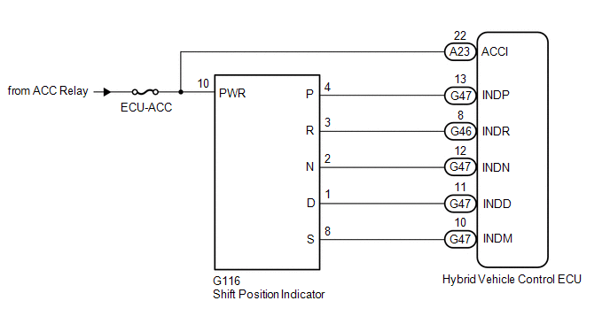
DESCRIPTION In accordance with the shift lever position, each shift position indicator light will turn on. WIRING DIAGRAM
 PROCEDURE
| 1. |
CHECK SHIFT POSITION INDICATOR | (a) Turn the power switch on (ACC).
(b) Check that each shift position indicator light turns on correctly.
|
Result | Proceed to | |
All shift position indicator lights turn on simultaneously |
A | | Shift position indicator lights other than corresponding one turn on |
B | | Corresponding shift position indicator light does not turn on |
C | | No shift position indicator lights turn on |
D | (c) Turn the power switch off.
| B |
 | GO TO STEP 2 |
| C |
| GO TO STEP 4 |
| D |
| GO TO STEP 4 |
|
A |
 | |
| 2. |
CHECK HARNESS AND CONNECTOR (CHECK FOR SHORT TO GND) |
(a) Disconnect the G46 and G47 hybrid vehicle control ECU connectors.
| (b) Measure the resistance according to the value(s) in the table below.
Standard Resistance: |
Tester Connection | Condition |
Specified Condition | |
G47-13 (INDP) - Body ground and other terminals |
Always | 10 kΩ or higher | |
G46-8 (INDR) - Body ground and other terminals |
Always | 10 kΩ or higher | |
G47-12 (INDN) - Body ground and other terminals |
Always | 10 kΩ or higher | |
G47-11 (INDD) - Body ground and other terminals |
Always | 10 kΩ or higher | |
G47-10 (INDM) - Body ground and other terminals |
Always | 10 kΩ or higher | |
 |
|
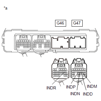
*a | Rear view of wire harness connector
(to Hybrid Vehicle Control ECU) | | |
(c) Reconnect the G46 and G47 hybrid vehicle control ECU connectors.
| OK |
| REPLACE HYBRID VEHICLE CONTROL ECU |
|
NG | |
| |
| 3. |
CHECK HARNESS AND CONNECTOR (HYBRID VEHICLE CONTROL ECU - SHIFT POSITION INDICATOR) |
(a) Disconnect the G46 and G47 hybrid vehicle control ECU connectors. (b) Disconnect the G116 shift position indicator connector.
| (c) Measure the resistance according to the value(s) in the table below.
Standard Resistance: |
Tester Connection | Condition |
Specified Condition | |
G47-13 (INDP) or G116-4 (P) - Body ground and other terminals |
Always | 10 kΩ or higher | |
G46-8 (INDR) or G116-3 (R) - Body ground and other terminals |
Always | 10 kΩ or higher | |
G47-12 (INDN) or G116-2 (N) - Body ground and other terminals |
Always | 10 kΩ or higher | |
G47-11 (INDD) or G116-1 (D) - Body ground and other terminals |
Always | 10 kΩ or higher | |
G47-10 (INDM) or G116-8 (S) - Body ground and other terminals |
Always | 10 kΩ or higher | |
 |
|
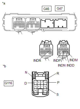
*a | Rear view of wire harness connector
(to Hybrid Vehicle Control ECU) | |
*b | Front view of wire harness connector
(to Shift Position Indicator) | | |
(d) Reconnect the G116 shift position indicator connector. (e) Reconnect the G46 and G47 hybrid vehicle control ECU connectors.
| OK |
| REPLACE SHIFT POSITION INDICATOR |
| NG |
| REPAIR OR REPLACE HARNESS OR CONNECTOR |
| 4. |
CHECK HARNESS AND CONNECTOR (POWER SOURCE CIRCUIT) |
(a) Disconnect the G116 shift position indicator connector. (b) Turn the power switch on (ACC).
| (c) Measure the voltage according to the value(s) in the table below.
Standard Voltage: |
Tester Connection | Condition |
Specified Condition | |
G116-10 (PWR) - Body ground |
Power switch on (ACC) |
11 to 14 V | |
 |
|
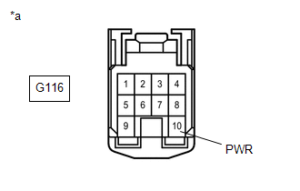
*a | Front view of wire harness connector
(to Shift Position Indicator) | | |
(d) Turn the power switch off. (e) Reconnect the G116 shift position indicator connector.
| NG |
| REPAIR OR REPLACE POWER SOURCE CIRCUIT |
|
OK | |
| |
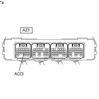
| 5. |
CHECK HARNESS AND CONNECTOR (POWER SOURCE TERMINAL ACCI) |
(a) Turn the power switch on (ACC).
| (b) Measure the voltage according to the value(s) in the table below.
Standard Voltage: |
Tester Connection | Condition |
Specified Condition | |
A23-22 (ACCI) - Body ground |
Power switch on (ACC) |
11 to 14 V | |
 |
|
*a | Component with harness connected
(Hybrid Vehicle Control ECU) | | |
(c) Turn the power switch off.
| NG | |
REPAIR OR REPLACE POWER SOURCE CIRCUIT |
|
OK | |
| |
| 6. |
CHECK HARNESS AND CONNECTOR (CHECK FOR OPEN) |
(a) Disconnect the G46 and G47 hybrid vehicle control ECU connectors. (b) Turn the power switch on (ACC).
| (c) Measure the voltage according to the value(s) in the table below.
Standard Voltage: |
Tester Connection | Condition |
Specified Condition | |
G47-13 (INDP) - Body ground and other terminals |
Power switch on (ACC) |
11 to 14 V | |
G46-8 (INDR) - Body ground and other terminals |
Power switch on (ACC) |
11 to 14 V | |
G47-12 (INDN) - Body ground and other terminals |
Power switch on (ACC) |
11 to 14 V | |
G47-11 (INDD) - Body ground and other terminals |
Power switch on (ACC) |
11 to 14 V | |
G47-10 (INDM) - Body ground and other terminals |
Power switch on (ACC) |
11 to 14 V | | |
|
|
*a | Rear view of wire harness connector
(to Hybrid Vehicle Control ECU) | | |
(d) Turn the power switch off. (e) Reconnect the G46 and G47 hybrid vehicle control ECU connectors.
| OK |
| REPLACE HYBRID VEHICLE CONTROL ECU |
|
NG | |
| |
| 7. |
CHECK HARNESS AND CONNECTOR (HYBRID VEHICLE CONTROL ECU - SHIFT POSITION INDICATOR) |
(a) Disconnect the G46 and G47 hybrid vehicle control ECU connectors. (b) Disconnect the G116 shift position indicator connector.
| (c) Measure the resistance according to the value(s) in the table below.
Standard Resistance: |
Tester Connection | Condition |
Specified Condition | |
G47-13 (INDP) - G116-4 (P) |
Always | Below 1 Ω | |
G46-8 (INDR) - G116-3 (R) |
Always | Below 1 Ω | |
G47-12 (INDN) - G116-2 (N) |
Always | Below 1 Ω | |
G47-11 (INDD) - G116-1 (D) |
Always | Below 1 Ω | |
G47-10 (INDM) - G116-8 (S) |
Always | Below 1 Ω | |
 |
|
*a | Rear view of wire harness connector
(to Hybrid Vehicle Control ECU) | |
*b | Front view of wire harness connector
(to Shift Position Indicator) | | |
(d) Reconnect the G116 shift position indicator connector. (e) Reconnect the G46 and G47 hybrid vehicle control ECU connectors.
| OK |
| REPLACE SHIFT POSITION INDICATOR |
| NG |
| REPAIR OR REPLACE HARNESS OR CONNECTOR | | 

