DESCRIPTION If the battery
voltage sensor detects an internal malfunction, it sends an error signal
to the hybrid vehicle control ECU. When the hybrid vehicle control ECU
receives the error signal from the battery voltage sensor, the ECU warns
the driver and performs fail-safe control. |
DTC No. | Detection Item |
DTC Detection Condition | Trouble Area |
MIL | Warning Indicate | |
P0AFC00 | Hybrid/EV Battery Sensor Module |
The hybrid vehicle control ECU receives an error signal from the battery voltage sensor.
(1 trip detection logic) |
- Battery voltage sensor
- Wire harness or connector
| Comes on |
Master Warning Light: Comes on | |
P0AFC16 | Hybrid/EV Battery Sensor Module Circuit Voltage Below Threshold |
The hybrid vehicle control ECU receives an error signal from the battery voltage sensor.
(1 trip detection logic) |
- Battery voltage sensor
- Wire harness or connector
| Comes on |
Master Warning Light: Comes on | |
P0AFC96 | Hybrid/EV Battery Sensor Module Component Internal Failure |
The hybrid vehicle control ECU receives an error signal from the battery voltage sensor.
(1 trip detection logic) |
- Battery voltage sensor
- Wire harness or connector
| Comes on |
Master Warning Light: Comes on | |
P308A12 | Hybrid/EV Battery Voltage Sensor All Circuit Short to Auxiliary Battery |
The hybrid vehicle control ECU receives an error signal from the battery voltage sensor.
(1 trip detection logic) |
- Battery voltage sensor
- Wire harness or connector
| Comes on |
Master Warning Light: Comes on | Related Data List |
DTC No. | Data List | |
P0AFC00 | Hybrid Battery Sensor Module Power Supply Voltage | |
P0AFC16 | | P0AFC96 | |
P308A12 | MONITOR DESCRIPTION
If
the battery voltage sensor detects an internal malfunction in the unit
itself, the hybrid vehicle control ECU will illuminate the MIL and store
a DTC. MONITOR STRATEGY |
Related DTCs | P0AFC (INF P0AFC00/P0AFC16/P0AFC96), P308D (INF P308A12): Hybrid Battery Pack Sensor Module | |
Required sensors/components | Battery voltage sensor | |
Frequency of operation | Continuous | |
Duration | TMC's intellectual property | |
MIL operation | Immediately | |
Sequence of operation | None | TYPICAL ENABLING CONDITIONS |
The monitor will run whenever the following DTCs are not stored |
TMC's intellectual property | | Other conditions belong to TMC's intellectual property |
- | TYPICAL MALFUNCTION THRESHOLDS |
TMC's intellectual property | - | COMPONENT OPERATING RANGE |
Battery voltage sensor | DTC P0AFC (INF P0AFC00/P0AFC16/P0AFC96) is not detected
DTC P308D (INF P308A12) is not detected | CONFIRMATION DRIVING PATTERN
HINT:
- After repair has been completed, clear the DTC and then check that the
vehicle has returned to normal by performing the following All Readiness
check procedure.
Click here 
- When clearing the permanent DTCs, refer to the "CLEAR PERMANENT DTC" procedure.
Click here
- Connect the Techstream to the DLC3.
- Turn the power switch on (IG) and turn the Techstream on.
- Clear the DTCs (even if no DTCs are stored, perform the clear DTC procedure).
- Turn the power switch off and wait for 2 minutes or more.
- Turn the power switch on (IG) and turn the Techstream on.
- With power switch on (IG) and wait for 10 seconds or more.[*1]
HINT:
[*1]: Normal judgment procedure.
The normal judgment procedure is used to complete DTC judgment and also used when clearing permanent DTCs.
- Enter the following menus: Powertrain / Hybrid Control / Utility / All Readiness.
- Check the DTC judgment result.
HINT:
- If the judgment result shows NORMAL, the system is normal.
- If the judgment result shows ABNORMAL, the system has a malfunction.
- If the judgment result shows INCOMPLETE or N/A, perform the normal judgment procedure again.
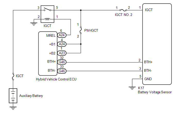
WIRING DIAGRAM
 CAUTION / NOTICE / HINT
CAUTION:
NOTICE: After
turning the power switch off, waiting time may be required before
disconnecting the cable from the negative (-) auxiliary battery
terminal. Therefore, make sure to read the disconnecting the cable from
the negative (-) auxiliary battery terminal notices before proceeding
with work. Click here PROCEDURE
| 1. |
CHECK HARNESS AND CONNECTOR (IGCT VOLTAGE) |
CAUTION: Be sure to wear insulated gloves. (a) Check that the service plug grip is not installed.
NOTICE:
- Check and record any DTCs, INF codes and freeze frame data, then
disconnect the cable from the negative (-) auxiliary battery terminal.
- After removing the service plug grip, do not turn the power switch on
(READY), unless instructed by the repair manual because this may cause a
malfunction.
(b) Remove the No. 1 hybrid battery exhaust duct. Click here
(c) Connect the cable to the negative (-) auxiliary battery terminal.
(d) Turn the power switch on (IG).
| (e) Measure the voltage according to the value(s) in the table below.
Standard Voltage: |
Tester Connection | Condition |
Specified Condition | |
K17-1 (IGCT) - K17-5 (GND) |
Power switch on (IG) |
11 to 14 V | NOTICE: Turning
the power switch on (IG) with the service plug grip removed causes
other DTCs to be stored. Clear the DTCs after performing this
inspection. |
 |
|
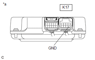
*a | Component with harness connected (Battery Voltage Sensor) | | |
(f) Turn the power switch off. (g) Disconnect the cable from the negative (-) auxiliary battery terminal.
(h) Install the No. 1 hybrid battery exhaust duct.
| OK |
 | REPLACE BATTERY VOLTAGE SENSOR |
|
NG |
 | |
| 2. |
CHECK HARNESS AND CONNECTOR (BATTERY VOLTAGE SENSOR - BODY GROUND) |
CAUTION: Be sure to wear insulated gloves. (a) Check that the service plug grip is not installed.
NOTICE: After
removing the service plug grip, do not turn the power switch on
(READY), unless instructed by the repair manual because this may cause a
malfunction. (b) Remove the No. 1 hybrid battery exhaust duct. Click here
| (c) Measure the resistance according to the value(s) in the table below.
Standard Resistance: |
Tester Connection | Condition |
Specified Condition | |
K17-5 (GND) - Body ground |
Power switch off |
Below 1 Ω | |
 |
|
*a | Component with harness connected (Battery Voltage Sensor) | | |
(d) Install the No. 1 hybrid battery exhaust duct.
| OK |
| REPAIR OR REPLACE HARNESS OR CONNECTOR (IGCT NO. 2 FUSE - BATTERY VOLTAGE SENSOR) |
| NG |
| REPAIR OR REPLACE HARNESS OR CONNECTOR (BATTERY VOLTAGE SENSOR - BODY GROUND) | |