DTC SUMMARY
MALFUNCTION DESCRIPTION
The hybrid vehicle control ECU detects malfunctions which prevent the inverter with converter assembly emergency shutdown circuit (HSDN) from shutting down the hybrid control system. Detection is performed when the power switch is turned on (IG) and during the shutdown sequence when the power switch is turned off.
The cause of this malfunction may be one of the following:
Hybrid vehicle control ECU and inverter with converter assembly shutdown circuit malfunctionDESCRIPTION
The hybrid vehicle control ECU sends a block signal to the motor generator control ECU (MG ECU) to shutdown the power supply to the motor. When the system is not in the on (READY) state, it sends an HSDN (MG shutdown signal) signal from the hybrid vehicle control ECU to the motor generator control ECU (MG ECU) to check the function of the HV gate block. When a malfunction is detected in the HV gate block function, DTCs are stored.
|
DTC No. | Detection Item |
DTC Detection Condition | Trouble Area |
MIL | Warning Indicate |
|---|---|---|---|---|---|
|
P321E9F | Motor/Generator Shutdown Signal Stuck Off |
When the HV gate block function check is performed (when the power switch is turned from on (READY) to off), the inverter voltage (VH) drops and current flows in the inverter. (1 trip detection logic) |
| Does not come on |
Master Warning Light: Comes on |
|
DTC No. | Data List |
|---|---|
|
P321E9F |
|
CONFIRMATION DRIVING PATTERN
HINT:
After repair has been completed, clear the DTC and then check that the vehicle has returned to normal by performing the following All Readiness check procedure.
Click here 
HINT:
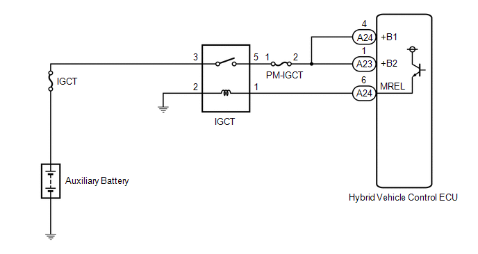
WIRING DIAGRAM
Refer to the wiring diagram for the shut down signal circuit.
Click here
CAUTION / NOTICE / HINT
CAUTION:


Click here
HINT:
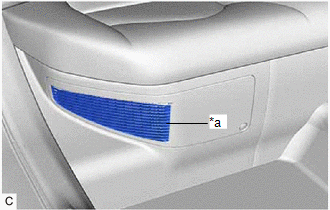
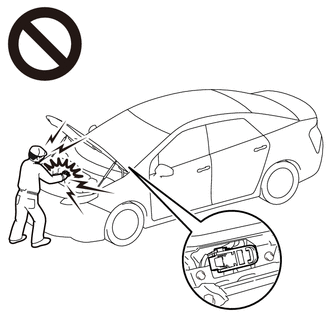
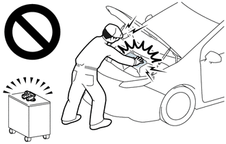
Waiting for at least 10 minutes is required to discharge the high-voltage capacitor inside the inverter with converter assembly.

|
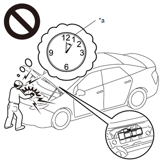
*a |
Without waiting for 10 minutes |
NOTICE:
After turning the power switch off, waiting time may be required before disconnecting the cable from the negative (-) auxiliary battery terminal. Therefore, make sure to read the disconnecting the cable from the negative (-) auxiliary battery terminal notices before proceeding with work.
Click here
PROCEDURE
| 1. |
CHECK DTC OUTPUT (HYBRID CONTROL) |
(a) Connect the Techstream to the DLC3.
(b) Turn the power switch on (IG).
(c) Enter the following menus: Powertrain / Hybrid Control / Trouble Codes.
(d) Check for DTCs.
Powertrain > Hybrid Control > Trouble Codes|
Result | Proceed to |
|---|---|
|
P321E9F only is output, or DTCs except the ones in the table below are also output |
A |
| Any of the following DTCs are also output |
B |
|
Malfunction Content |
Relevant DTC | |
|---|---|---|
| Sensor and actuator circuit malfunction |
P33B99F | Motor/Generator Shutdown Signal (Hybrid/EV Side) Stuck Off |
|
P33BF9F | Motor/Generator Shutdown Signal (MG Side) Stuck Off | |
HINT:
(e) Turn the power switch off.
| B |
 | GO TO DTC CHART (HYBRID CONTROL SYSTEM) |
|
| 2. |
CHECK CONNECTOR CONNECTION CONDITION (HYBRID VEHICLE CONTROL ECU CONNECTOR) |
Click here
| NG | | CONNECT SECURELY |
|
| 3. |
CHECK CONNECTOR CONNECTION CONDITION (INVERTER WITH CONVERTER ASSEMBLY CONNECTOR) |
Click here
|
Result | Proceed to |
|---|---|
|
OK | A |
|
NG (The connector is not connected securely.) |
B |
| NG (The terminals are not making secure contact or are deformed, or water or foreign matter exists in the connector.) |
C |
| B |
| CONNECT SECURELY |
| C |
| REPAIR OR REPLACE HARNESS OR CONNECTOR |
|
| 4. |
CHECK HARNESS AND CONNECTOR (INVERTER WITH CONVERTER ASSEMBLY - HYBRID VEHICLE CONTROL ECU) |
CAUTION:
Be sure to wear insulated gloves.
(a) Check that the service plug grip is not installed.
NOTICE:
After removing the service plug grip, do not turn the power switch on (READY), unless instructed by the repair manual because this may cause a malfunction.
(b) Disconnect the A42 inverter with converter assembly connector.
(c) Disconnect the A24 hybrid vehicle control ECU connector.
| (d) Measure the resistance according to the value(s) in the table below. Standard Resistance:
|
|
(e) Reconnect the A24 hybrid vehicle control ECU connector.
(f) Reconnect the A42 inverter with converter assembly connector.
| NG | | REPAIR OR REPLACE HARNESS OR CONNECTOR |
|
| 5. |
CHECK INVERTER WITH CONVERTER ASSEMBLY |
CAUTION:
Be sure to wear insulated gloves.
(a) Check that the service plug grip is not installed.
NOTICE:
After removing the service plug grip, do not turn the power switch on (READY), unless instructed by the repair manual because this may cause a malfunction.
(b) Disconnect the A42 inverter with converter assembly connector.
| (c) Measure the resistance according to the value(s) in the table below. Standard Resistance:
NOTICE: Be sure not to damage or deform the terminal being inspected. |
|
(d) Reconnect the A42 inverter with converter assembly connector.
| OK | | REPLACE HYBRID VEHICLE CONTROL ECU |
| NG | | REPLACE INVERTER WITH CONVERTER ASSEMBLY |
DESCRIPTION
This DTC indicates that the hybrid vehicle control ECU detected an instantaneous interruption in +B power source voltage.
|
DTC No. | Detection Item |
DTC Detection Condition | Trouble Area |
MIL | Warning Indicate |
|---|---|---|---|---|---|
|
P06881F | ECM/PCM Power Relay Sense Circuit Intermittent |
When the power switch is on (READY), the hybrid vehicle control ECU is reset due to an instantaneous interruption of power source. (1 trip detection logic) |
| Does not come on |
Master Warning Light: Comes on |
CONFIRMATION DRIVING PATTERN
HINT:
After repair has been completed, clear the DTC and then check that the vehicle has returned to normal by performing the following All Readiness check procedure.
Click here 
(If the DTC is not output, drive the vehicle on urban roads according to the freeze frame data item "Vehicle Speed" for approximately 5 minutes.)
HINT:
WIRING DIAGRAM
PROCEDURE
| 1. |
CHECK AUXILIARY BATTERY TERMINAL |
(a) Confirm whether the auxiliary battery terminals have been disconnected recently.
|
Result | Proceed to |
|---|---|
|
Terminals have been disconnected. |
A |
| Terminals have not been disconnected. |
B |
| B |
 | GO TO STEP 5 |
|
| 2. |
CONFIRM MASTER WARNING LIGHT |
(a) Turn the power switch on (READY) from off.
(b) Confirm that the master warning light illuminates.
| Result |
Proceed to |
|---|---|
| Master warning light illuminates. |
A |
| Master warning light does not illuminate. |
B |
NOTICE:
DTC P06881F may be stored after disconnecting and reconnecting the auxiliary battery terminals. If this happens, the DTC will not be output if the power switch is turned off and then on (READY) again. In this case, clear the DTCs to complete the inspection.
(c) Turn the power switch off.
| B |
| END |
|
| 3. |
CLEAR DTC |
(a) Connect the Techstream to the DLC3.
(b) Turn the power switch on (IG).
(c) Enter the following menus: Powertrain / Hybrid Control / Trouble Codes.
(d) Read and record the DTCs and freeze frame data.
Powertrain > Hybrid Control > Trouble Codes(e) Clear the DTCs and freeze frame data.
Powertrain > Hybrid Control > Clear DTCs(f) Turn the power switch off and wait for 2 minutes or more.
|
| 4. |
CHECK DTC OUTPUT (HYBRID CONTROL) |
(a) Connect the Techstream to the DLC3.
(b) Turn the power switch on (IG).
(c) Enter the following menus: Powertrain / Hybrid Control / Trouble Codes.
(d) Check for DTCs.
Powertrain > Hybrid Control > Trouble Codes| Result |
Proceed to |
|---|---|
| DTC P06881F is output again. |
A |
| DTCs other than P06881F are also output. |
B |
(e) Turn the power switch off.
| B |
| GO TO DTC CHART (HYBRID CONTROL SYSTEM) |
|
| 5. |
CHECK AUXILIARY BATTERY TERMINAL (CONTACT PROBLEM) |
(a) Check the connection of the auxiliary battery terminal.
OK:
The terminal is connected securely and there is no contact problem.
| NG | | CONNECT SECURELY |
|
| 6. |
CHECK CONNECTOR CONNECTION CONDITION (HYBRID VEHICLE CONTROL ECU CONNECTOR) |
Click here
| NG | | CONNECT SECURELY |
|
| 7. |
CHECK HARNESS AND CONNECTOR (HYBRID VEHICLE CONTROL ECU - IGCT RELAY) |
(a) Remove the IGCT relay from the No. 3 relay block.
(b) Disconnect the A23 and A24 hybrid vehicle control ECU connectors.
(c) Measure the resistance according to the value(s) in the table below.
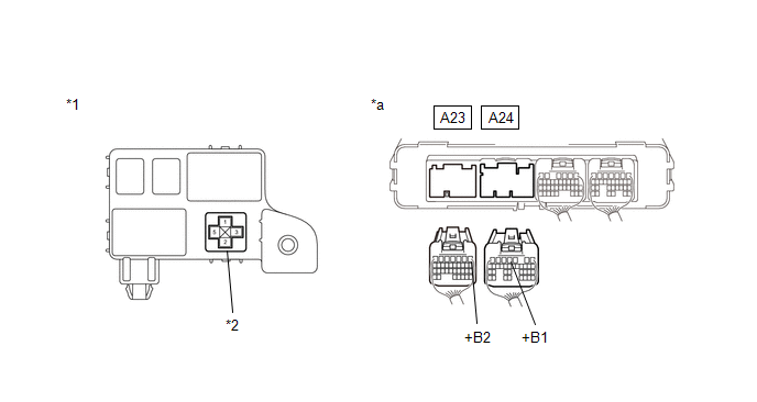
|
*1 | No. 3 Relay Block |
*2 | IGCT Relay Holder |
|
*a | Rear view of wire harness connector (to Hybrid Vehicle Control ECU) |
- | - |
Standard Resistance:
|
Tester Connection | Condition |
Specified Condition |
|---|---|---|
|
A24-4 (+B1) - 5 (IGCT relay holder) |
Power switch off | Below 1 Ω |
|
A23-1 (+B2) - 5 (IGCT relay holder) |
Power switch off | Below 1 Ω |
(d) Reconnect the A23 and A24 hybrid vehicle control ECU connectors.
(e) Reinstall the IGCT relay.
| NG | | REPAIR OR REPLACE HARNESS OR CONNECTOR |
|
| 8. |
CHECK FOR INTERMITTENT PROBLEMS |
(a) Check for intermittent problems.
Click here
(1) Check the connection and terminal contact pressure of the connectors and wire harnesses between the hybrid vehicle control ECU and the No. 3 relay block.
(2) When the power switch is on (READY), jiggle the connectors and wire harnesses between the hybrid vehicle control ECU and the No. 3 relay block.
| Result |
Proceed to |
|---|---|
| Problem symptom does not recur. |
A |
| Problem symptom recurs. |
B |
| A |
| REPLACE HYBRID VEHICLE CONTROL ECU |
| B |
| REPAIR OR REPLACE MALFUNCTIONING PARTS, COMPONENT AND AREA |
DESCRIPTION
The hybrid vehicle control ECU monitors its internal operation and detects the following malfunction.
|
DTC No. | Detection Item |
DTC Detection Condition | Trouble Area |
MIL | Warning Indicate |
|---|---|---|---|---|---|
|
P30004B | Hybrid/EV Battery Control System Over Temperature |
The HV battery temperature becomes too high due to a malfunction in the HV system. (1 trip detection logic) |
| Does not come on |
Master Warning Light: Comes on |
|
DTC No. | Data List |
|---|---|
|
P30004B |
|
CONFIRMATION DRIVING PATTERN
HINT:
After repair has been completed, clear the DTC and then check that the vehicle has returned to normal by performing the following All Readiness check procedure.
Click here 
HINT:
CAUTION / NOTICE / HINT
CAUTION:
|
*a |
Without waiting for 10 minutes |
Click here
HINT:
Waiting for at least 10 minutes is required to discharge the high-voltage capacitor inside the inverter with converter assembly.
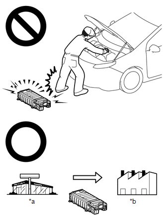
If the HV battery stored without insulating the connectors and terminals, electric shock or fire may result.
|
*a |
Dealer |
|
*b |
Battery Collection Agent |
NOTICE:
After turning the power switch off, waiting time may be required before disconnecting the cable from the negative (-) auxiliary battery terminal. Therefore, make sure to read the disconnecting the cable from the negative (-) auxiliary battery terminal notices before proceeding with work.
Click here
PROCEDURE
| 1. |
CHECK DTC OUTPUT (HYBRID CONTROL) |
(a) Connect the Techstream to the DLC3.
(b) Turn the power switch on (IG).
(c) Enter the following menus: Powertrain / Hybrid Control / Trouble Codes.
(d) Check for DTCs.
Powertrain > Hybrid Control > Trouble Codes|
Result | Proceed to |
|---|---|
|
P30004B only is output. |
A |
| DTCs other than P30004B are also output. |
B |
(e) Turn the power switch off.
| B |
 | GO TO DTC CHART (HYBRID CONTROL SYSTEM) |
|
| 2. |
CLEAN NO. 1 HV BATTERY INTAKE FILTER |
| (a) Check the HV battery cooling system intake port for blockage. HINT: If anything is blocking the HV battery cooling system intake port, remove it. |
|
(b) Clean the No. 1 HV battery intake filter.
Click here
|
| 3. |
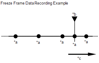
CHECK FREEZE FRAME DATA (HYBRID CONTROL) |
(a) Connect the Techstream to the DLC3.
(b) Turn the power switch on (IG).
(c) Enter the following menus: Powertrain / Hybrid Control / Trouble Codes.
(d) Read the freeze frame data of DTC P30004B.
Powertrain > Hybrid Control > Trouble CodesNOTICE:
Although freeze frame data is recorded before and after a DTC is stored, for this step it is only necessary to read the freeze frame data recorded before "0s" (when the DTC was stored).
|
*a | Freeze Frame Data Recorded |
|
*b | DTC Stored |
|
*c | Time |
|
Result | Proceed to |
|---|---|
|
Other than below | A |
|
The difference between the value of "VL-Voltage before Boosting" and the total of "Hybrid Battery Block 1 to 11 Voltage" is 10 V or more. |
B |
(e) Turn the power switch off.
| B |
| GO TO STEP 7 |
|
| 4. |
CHECK FREEZE FRAME DATA (HYBRID CONTROL) |
(a) Connect the Techstream to the DLC3.
(b) Turn the power switch on (IG).
(c) Enter the following menus: Powertrain / Hybrid Control / Trouble Codes.
(d) Read the freeze frame data of DTC P30004B.
Powertrain > Hybrid Control > Trouble CodesNOTICE:
Although freeze frame data is recorded before and after a DTC is stored, for this step it is only necessary to read the freeze frame data recorded at "0s" (when the DTC was stored).
|
Result | Proceed to |
|---|---|
|
Other than below | A |
|
The value of any of "Hybrid Battery Temperature 1 to 3" is 80°C (176°F) or more. |
B |
(e) Turn the power switch off.
| B |
| GO TO STEP 8 |
|
| 5. |
READ VALUE USING TECHSTREAM (DATA LIST) |
(a) Apply the parking brake and secure the wheels using chocks.
(b) Connect the Techstream to the DLC3.
(c) Turn the power switch on (READY).
(d) Enter the following menus: Powertrain / Hybrid Control / Data List / Hybrid Battery Temperature 1 to 3.
Powertrain > Hybrid Control > Data List|
Tester Display |
|---|
| Hybrid Battery Temperature 1 |
|
Hybrid Battery Temperature 2 |
|
Hybrid Battery Temperature 3 |
(e) According to the display on the Techstream, read the Data List and check that the value of each "Hybrid Battery Temperature 1 to 3" is 40°C (104°F) or less.
HINT:
If the value of any of "Hybrid Battery Temperature 1 to 3" is more than 40°C (104°F), turn the power switch off and wait until the values to decrease to 40°C (104°F) or less before continuing this procedure.
(f) Enter the following menus: Powertrain / Hybrid Control / Data List / Hybrid Battery Block 1, 2, 9, 10, 11 Voltage.
Powertrain > Hybrid Control > Data List|
Tester Display |
|---|
| Hybrid Battery Block 1 Voltage |
|
Hybrid Battery Block 2 Voltage |
|
Hybrid Battery Block 9 Voltage |
|
Hybrid Battery Block 10 Voltage |
|
Hybrid Battery Block 11 Voltage |
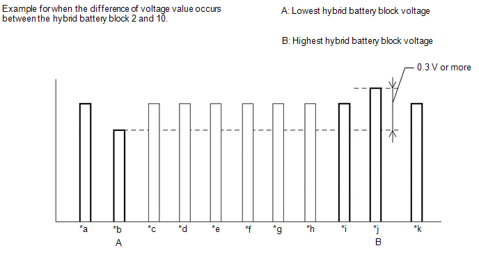
(g) According to the display on the Techstream, read the Data List and check the value of each "Hybrid Battery Block 1, 2, 9, 10 and 11 Voltage" with the power switch on (IG).
|
*a | Hybrid Battery Block 1 Voltage |
*b | Hybrid Battery Block 2 Voltage |
|
*c | Hybrid Battery Block 3 Voltage |
*d | Hybrid Battery Block 4 Voltage |
|
*e | Hybrid Battery Block 5 Voltage |
*f | Hybrid Battery Block 6 Voltage |
|
*g | Hybrid Battery Block 7 Voltage |
*h | Hybrid Battery Block 8 Voltage |
|
*i | Hybrid Battery Block 9 Voltage |
*j | Hybrid Battery Block 10 Voltage |
|
*k | Hybrid Battery Block 11 Voltage |
- | - |
|
Result | Proceed to |
|---|---|
|
Other than below | A |
|
The difference between the lowest and highest HV Battery Block Voltage is 0.3 V or more. |
B |
(h) Turn the power switch off.
| B |
| GO TO STEP 8 |
|
| 6. |
READ VALUE USING TECHSTREAM (DATA LIST) |
(a) Apply the parking brake and secure the wheels using chocks.
(b) Connect the Techstream to the DLC3.
(c) Turn the power switch on (READY).
(d) Enter the following menus: Powertrain / Hybrid Control / Data List / Hybrid Battery Temperature 1 to 3.
Powertrain > Hybrid Control > Data List|
Tester Display |
|---|
| Hybrid Battery Temperature 1 |
|
Hybrid Battery Temperature 2 |
|
Hybrid Battery Temperature 3 |
(e) According to the display on the Techstream, read the Data List and check that the value of each "Hybrid Battery Temperature 1 to 3" is 40°C (104°F) or less.
HINT:
If the value of any of "Hybrid Battery Temperature 1 to 3" is more than 40°C (104°F), turn the power switch off and wait until the values to decrease to 40°C (104°F) or less before continuing this procedure.
(f) Enter the following menus: Powertrain / Hybrid Control / Data List / Hybrid Battery Block 3 to 8 Voltage.
Powertrain > Hybrid Control > Data List|
Tester Display |
|---|
| Hybrid Battery Block 3 Voltage |
|
Hybrid Battery Block 4 Voltage |
|
Hybrid Battery Block 5 Voltage |
|
Hybrid Battery Block 6 Voltage |
|
Hybrid Battery Block 7 Voltage |
|
Hybrid Battery Block 8 Voltage |
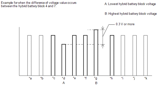
(g) According to the display on the Techstream, read the Data List and check the value of each "Hybrid Battery Block 3 to 8 Voltage" with the power switch on (IG).
|
*a | Hybrid Battery Block 1 Voltage |
*b | Hybrid Battery Block 2 Voltage |
|
*c | Hybrid Battery Block 3 Voltage |
*d | Hybrid Battery Block 4 Voltage |
|
*e | Hybrid Battery Block 5 Voltage |
*f | Hybrid Battery Block 6 Voltage |
|
*g | Hybrid Battery Block 7 Voltage |
*h | Hybrid Battery Block 8 Voltage |
|
*i | Hybrid Battery Block 9 Voltage |
*j | Hybrid Battery Block 10 Voltage |
|
*k | Hybrid Battery Block 11 Voltage |
- | - |
|
Result | Proceed to |
|---|---|
|
Other than below | A |
|
The difference between the lowest and highest HV Battery Block Voltage is 0.3 V or more. |
B |
(h) Turn the power switch off.
| A |
| END |
| B |
| GO TO STEP 8 |
| 7. |
REPLACE BATTERY VOLTAGE SENSOR |
Click here
| NEXT | |
REPLACE HV BATTERY |
| 8. |
REPLACE HYBRID VEHICLE CONTROL ECU |
Click here
| NEXT | |
REPLACE HV BATTERY |
Toyota Avalon (XX50) 2019-2022 Service & Repair Manual > Airbag System(for Gasoline Model): Short in Curtain Shield Airbag (LH) Squib Circuit (B1835-B1838). Short in Rear Side Squib RH Circuit (B1850-B1853). Short in Rear Side Squib LH Circuit (B1855-B1858)
Short in Curtain Shield Airbag (LH) Squib Circuit (B1835-B1838) DESCRIPTION The curtain shield squib LH circuit consists of the airbag ECU assembly and curtain shield airbag assembly LH. The airbag ECU assembly uses this circuit to deploy the airbag when deployment conditions are met. These DTCs are ...