DESCRIPTION For a description of the inverter.
Click here  The
MG ECU, which is built into in the inverter with converter assembly,
controls motor (MG2) based on commands from the hybrid vehicle control
ECU. The MG ECU monitors communication data and detects malfunctions. The hybrid vehicle control ECU monitors communication data and detects malfunctions.
A communication error between the MG ECU and the hybrid vehicle control ECU. |
DTC No. | Detection Item |
DTC Detection Condition | Trouble Area |
MIL | Warning Indicate | |
P312387 | Lost Communication with Drive Motor Control Module "A" from Hybrid/EV Control Module Missing Message |
Error in reception from inverter with converter assembly (MG ECU) via serial communication (out of communication standard)
(1 trip detection logic) |
- Wire harness or connector
- Inverter with converter assembly
- Hybrid vehicle transaxle assembly
- Hybrid vehicle control ECU
- PCU fuse
| Comes on |
Master Warning Light: Comes on | MONITOR DESCRIPTION
The hybrid vehicle control ECU monitors communication data and detects malfunctions, it will illuminate the MIL and store a DTC. MONITOR STRATEGY |
Related DTCs | P3123 (INF P312387): Lost Communication With Drive Motor "A" Control Module Verify communication | |
Required sensors / components | Main: Hybrid vehicle control ECU
Sub: Inverter with converter assembly | | Frequency of operation |
Continuous | | Duration | TMC's intellectual property | |
MIL operation | Immediately | | Sequence of operation |
None | TYPICAL ENABLING CONDITIONS |
The monitor will run whenever the following DTCs are not present |
TMC's intellectual property | | Other conditions belong to TMC's intellectual property |
- | TYPICAL MALFUNCTION THRESHOLDS |
TMC's intellectual property |
- | COMPONENT OPERATING RANGE |
Hybrid vehicle control ECU | DTC P3123 (INF P312387) is not detected | CONFIRMATION DRIVING PATTERN
HINT:
- After repair has been completed, clear the DTCs and then check that the
vehicle has returned to normal by performing the following All Readiness
check procedure.
Click here
- When clearing the permanent DTCs, refer to the "CLEAR PERMANENT DTC" procedure.
Click here
- Connect the Techstream to the DLC3.
- Turn the power switch on (IG) and turn the Techstream on.
- Clear the DTCs (even if no DTCs are stored, perform the clear DTC procedure).
- Turn the power switch off and wait for 2 minutes or more.
- Turn the power switch on (IG) and turn the Techstream on.
- With power switch on (IG) and wait for 2 minutes or more.[*1]
HINT:
[*1] : Normal judgment procedure.
The normal judgment procedure is used to complete DTC judgment and also used when clearing permanent DTCs.
- Enter the following menus: Powertrain / Hybrid Control / Utility / All Readiness.
- Check the DTC judgment result.
HINT:
- If the judgment result shows NORMAL, the system is normal.
- If the judgment result shows ABNORMAL, the system has a malfunction.
- If the judgment result shows INCOMPLETE or N/A, perform the normal judgment procedure again.
WIRING DIAGRAM Refer to the wiring diagram for the inverter low-voltage circuit.
Click here CAUTION / NOTICE / HINT
CAUTION:
NOTICE: After
turning the power switch off, waiting time may be required before
disconnecting the cable from the negative (-) auxiliary battery
terminal. Therefore, make sure to read the disconnecting the cable from
the negative (-) auxiliary battery terminal notices before proceeding
with work. Click here PROCEDURE
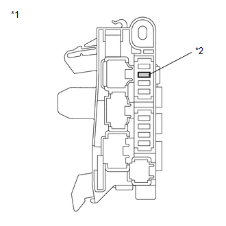
(a) Remove the PCU fuse from the No. 4 relay block.
| (b) Measure the resistance according to the value(s) in the table below.
Standard Resistance: |
Tester Connection | Condition |
Specified Condition | |
PCU fuse | Always |
Below 1 Ω | |
 |
|
*1 | No. 4 Relay Block | |
*2 | PCU Fuse | | |
(c) Install the PCU fuse.
| NG |  |
GO TO STEP 9 |
|
OK |
 | |
Click here
|
NEXT | |
| |
| 3. |
CHECK DIAGNOSIS RELATED INFORMATION AND DTC OUTPUT (HYBRID CONTROL) |
(a) Connect the Techstream to the DLC3. (b) Turn the power switch on (IG) and wait for 2 minutes or more.
(c) Enter the following menus: Powertrain / Hybrid Control / Utility / Diagnosis Related Information. Powertrain > Hybrid Control > Utility
|
Tester Display | | Diagnosis Related Information |
(d) Enter the following menus: Powertrain / Hybrid Control / Trouble Codes. Powertrain > Hybrid Control > Trouble Codes
(e) Check for DTCs. | Result |
Proceed to | | P312387 is listed in Diagnosis Related Information or DTC P312387 is output |
A | | P312387 is not listed in Diagnosis Information and DTC P312387 is not output |
B | (f) Turn the power switch off.
| B |
| CHECK FOR INTERMITTENT PROBLEMS |
|
A | |
| |
| 4. |
CHECK CONNECTOR CONNECTION CONDITION (HYBRID VEHICLE CONTROL ECU CONNECTOR) |
Click here
| NG |
| CONNECT SECURELY |
|
OK | |
| |
| 5. |
CHECK CONNECTOR CONNECTION CONDITION (INVERTER WITH CONVERTER ASSEMBLY CONNECTOR) |
Click here
|
Result | Proceed to | |
OK | A | |
NG (The connector is not connected securely.) |
B | | NG (The terminals are not making secure contact or are deformed, or water or foreign matter exists in the connector.) |
C |
| B |
| CONNECT SECURELY |
| C |
| REPAIR OR REPLACE HARNESS OR CONNECTOR |
|
A | |
| |
| 6. |
CHECK HARNESS AND CONNECTOR (INVERTER WITH CONVERTER ASSEMBLY POWER SOURCE CIRCUIT) |
CAUTION: Be sure to wear insulated gloves. (a) Check that the service plug grip is not installed.
NOTICE: After
removing the service plug grip, do not turn the power switch on
(READY), unless instructed by the repair manual because this may cause a
malfunction. (b) Disconnect the A42 inverter with converter assembly connector.
| (c) Measure the resistance according to the value(s) in the table below.
Standard Resistance: |
Tester Connection | Condition |
Specified Condition | |
A42-24 (GND1) - Body ground |
Power switch off |
Below 1 Ω | |
A42-23 (GND2) - Body ground |
Power switch off |
Below 1 Ω | |
 |
|
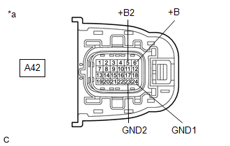
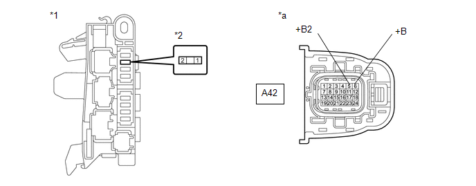
*a | Front view of wire harness connector
(to Inverter with Converter Assembly) | | |
(d) Connect the cable to the negative (-) auxiliary battery terminal. (e) Turn the power switch on (IG).
(f) Measure the voltage according to the value(s) in the table below. Standard Voltage: |
Tester Connection | Condition |
Specified Condition | |
A42-6 (+B) - Body ground |
Power switch on (IG) |
11 to 14 V | |
A42-5 (+B2) - Body ground |
Power switch on (IG) |
11 to 14 V | NOTICE: Turning
the power switch on (IG) with the inverter with converter assembly
disconnected causes other DTCs to be stored. Clear the DTCs after
performing this inspection. (g) Turn the power switch off. (h) Disconnect the cable from the negative (-) auxiliary battery terminal and wait for 2 minutes or more.
(i) Reconnect the A42 inverter with converter assembly connector.
| NG |
| REPAIR OR REPLACE HARNESS OR CONNECTOR |
|
OK | |
| |
| 7. |
CHECK HARNESS AND CONNECTOR (INVERTER WITH CONVERTER ASSEMBLY - HYBRID VEHICLE CONTROL ECU) |
CAUTION: Be sure to wear insulated gloves. (a) Check that the service plug grip is not installed.
NOTICE: After
removing the service plug grip, do not turn the power switch on
(READY), unless instructed by the repair manual because this may cause a
malfunction. (b) Disconnect the A42 inverter with converter assembly connector.
(c) Disconnect the A24 hybrid vehicle control ECU connector. (d) Connect the cable to the negative (-) auxiliary battery terminal.
(e) Turn the power switch on (IG).
| (f) Measure the voltage according to the value(s) in the table below.
Standard Voltage: |
Tester Connection | Condition |
Specified Condition | |
A24-30 (HMCL) - Body ground |
Power switch on (IG) |
Below 1 V | |
A24-31 (HMCH) - Body ground |
Power switch on (IG) |
Below 1 V | NOTICE: Turning
the power switch on (IG) with the hybrid vehicle control ECU connector
and the inverter with converter assembly disconnected causes other DTCs
to be stored. Clear the DTCs after performing this inspection. |
 |
|
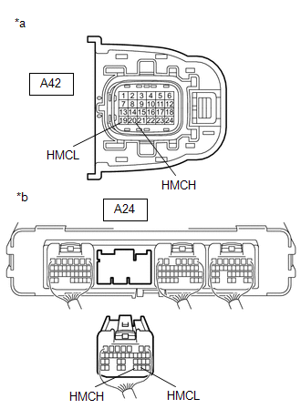
*a | Front view of wire harness connector
(to Inverter with Converter Assembly) | |
*b | Rear view of wire harness connector
(to Hybrid Vehicle Control ECU) | | |
(g) Turn the power switch off. (h) Disconnect the cable from the negative (-) auxiliary battery terminal and wait for 2 minutes or more.
(i) Measure the resistance according to the value(s) in the table below.
Standard Resistance (Check for Open): |
Tester Connection | Condition |
Specified Condition | |
A42-19 (HMCL) - A24-30 (HMCL) |
Power switch off | Below 1 Ω | |
A42-20 (HMCH) - A24-31 (HMCH) |
Power switch off | Below 1 Ω |
Standard Resistance (Check for Short): |
Tester Connection | Condition |
Specified Condition | |
A42-19 (HMCL) or A24-30 (HMCL) - Body ground and other terminals |
Power switch off | 10 kΩ or higher | |
A42-20 (HMCH) or A24-31 (HMCH) - Body ground and other terminals |
Power switch off | 10 kΩ or higher |
(j) Reconnect the A24 hybrid vehicle control ECU connector. (k) Reconnect the A42 inverter with converter assembly connector.
| NG |
| REPAIR OR REPLACE HARNESS OR CONNECTOR |
|
OK | |
| |
| 8. |
CHECK HYBRID VEHICLE CONTROL ECU | CAUTION:
Be sure to wear insulated gloves. (a) Check that the service plug grip is not installed.
NOTICE: After
removing the service plug grip, do not turn the power switch on
(READY), unless instructed by the repair manual because this may cause a
malfunction. (b) Disconnect the A42 inverter with converter assembly connector.
| (c) Measure the resistance according to the value(s) in the table below.
Standard Resistance: |
Tester Connection | Condition |
Specified Condition | |
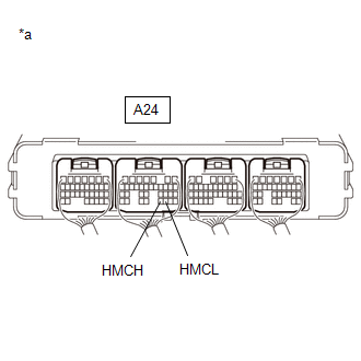
A24-30 (HMCL) -A24-31 (HMCH) |
Power switch off |
110 to 130 Ω | |
 |
|
*a | Component with harness connected
(Hybrid Vehicle Control ECU) | | |
(d) Reconnect the A42 inverter with converter assembly connector.
| OK |
| REPLACE INVERTER WITH CONVERTER ASSEMBLY |
| NG |
| REPLACE HYBRID VEHICLE CONTROL ECU |
| (a) Replace the PCU fuse. |
 |
|
*1 | No. 4 Relay Block | |
*2 | PCU Fuse | | |
(b) Turn the power switch on (READY). (c) Check if there is an open circuit in the PCU fuse in the No. 4 relay block.
OK: There is no open circuit in the PCU fuse. HINT: If
the fuse does not become open again after turning the power switch on
(READY), it can be assumed that the previous fuse failed due to age. (d) Turn the power switch off.
| OK |
| END |
|
NG | |
| |
| 10. |
CHECK HARNESS AND CONNECTOR (INVERTER WITH CONVERTER ASSEMBLY - PCU FUSE) |
CAUTION: Be sure to wear insulated gloves. (a) Check that the service plug grip is not installed.
NOTICE: After
removing the service plug grip, do not turn the power switch on
(READY), unless instructed by the repair manual because this may cause a
malfunction. (b) Remove the PCU fuse from the No. 4 relay block. (c) Disconnect the A42 inverter with converter assembly connector.
(d) Measure the resistance according to the value(s) in the table below.
|
*1 | No. 4 Relay Block |
*2 | PCU Fuse Holder | |
*a | Front view of wire harness connector
(to Inverter with Converter Assembly) |
- | - |
Standard Resistance (Check for Short): |
Tester Connection | Condition |
Specified Condition | |
A42-6 (+B), A42-5 (+B2) or 2 (PCU fuse holder) - Body ground and other terminals |
Power switch off | 10 kΩ or higher |
(e) Reconnect the A42 inverter with converter assembly connector. (f) Install the PCU fuse.
| NG |
| GO TO STEP 12 |
|
OK | |
| |
| 11. |
REPLACE INVERTER WITH CONVERTER ASSEMBLY |
Click here
| NEXT |
| REPLACE FUSE (PCU) |
| 12. |
REPAIR OR REPLACE HARNESS OR CONNECTOR |
| NEXT |
| REPLACE FUSE (PCU) | |