DTC SUMMARY
Refer to the DTC summary for DTC P1C7779.
Click here 
DESCRIPTION
Refer to the description for DTC P1C7779.
Click here
|
DTC No. | Detection Item |
DTC Detection Condition | Trouble Area |
MIL | Warning Indicate |
|---|---|---|---|---|---|
|
P314779 | Transmission (Shaft) Mechanical Linkage Failure |
Drive force from motor (MG2) or the engine cannot be transmitted to the wheels. The engine, generator (MG1), motor (MG2) or hybrid vehicle transaxle assembly does not run smoothly due to a mechanical malfunction. (1 trip detection logic) |
| Does not come on |
Master Warning Light: Comes on |
|
DTC No. | Data List |
|---|---|
|
P314779 |
|
CONFIRMATION DRIVING PATTERN
HINT:
After repair has been completed, clear the DTCs and then check that the vehicle has returned to normal by performing the following All Readiness check procedure.
Click here
HINT:
CAUTION / NOTICE / HINT
HINT:
PROCEDURE
|
1. | CHECK DTC OUTPUT (ENGINE) |
(a) Connect the Techstream to the DLC3.
(b) Turn the power switch on (IG).
(c) Enter the following menus: Powertrain / Engine / Trouble Codes.
Powertrain > Engine > Trouble Codes(d) Check for DTCs.
|
Result | Proceed to |
|---|---|
|
No DTCs are output, or DTCs except the ones in the table below are also output |
A |
| Any of the following DTCs are also output |
B |
|
Relevant DTC | |
|---|---|
| P033511 |
Crankshaft Position Sensor "A" Circuit Short to Ground |
|
P033515 | Crankshaft Position Sensor "A" Circuit Short to Battery or Open |
|
P03352A | Crankshaft Position Sensor "A" Signal Stuck in Range |
|
P033531 | Crankshaft Position Sensor "A" No Signal |
(e) Turn the power switch off.
| B |  |
GO TO DTC CHART (SFI SYSTEM) |
|
| 2. |
CHECK CRANKSHAFT PULLEY REVOLUTION (P POSITION) |
Click here
| NG | | GO TO STEP 7 |
|
| 3. |
CLEAR DTC |
Click here
|
| 4. |
CHECK ENGINE RACING |
Click here
| NG | |
REPLACE HYBRID VEHICLE TRANSAXLE ASSEMBLY |
|
| 5. |
CHECK CREEP MOVEMENT |
Click here
| NG | |
REPLACE HYBRID VEHICLE TRANSAXLE ASSEMBLY |
|
| 6. |
INSPECT ENGINE SPEED |
Click here
|
Result | Proceed to |
|---|---|
|
The absolute value of the difference is less than 500 rpm |
A |
| The absolute value of the difference is 500 rpm or more continuously for 1 second |
B |
| A |
| REPLACE HYBRID VEHICLE TRANSAXLE ASSEMBLY |
| B |
| REPLACE TRANSMISSION INPUT DAMPER ASSEMBLY |
| 7. |
CHECK CRANKSHAFT PULLEY REVOLUTION (N POSITION) |
Click here
| OK | | REPLACE HYBRID VEHICLE TRANSAXLE ASSEMBLY |
| NG | | REPAIR OR REPLACE ENGINE |
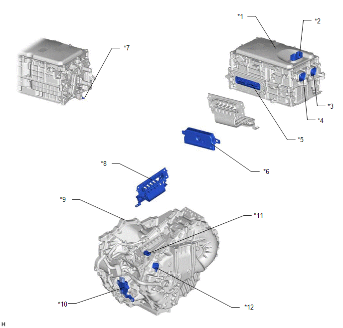
PARTS LOCATION
ILLUSTRATION
|
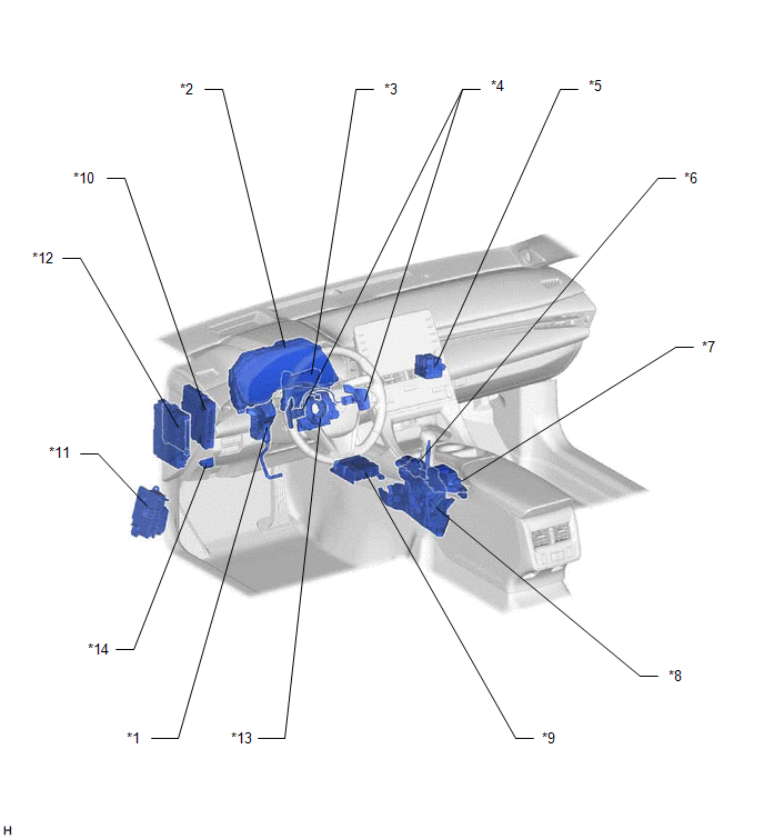
*1 | ACCELERATOR PEDAL SENSOR ASSEMBLY |
*2 | COMBINATION METER ASSEMBLY |
|
*3 | AIR CONDITIONING AMPLIFIER ASSEMBLY |
*4 | SHIFT PADDLE SWITCH (TRANSMISSION SHIFT SWITCH ASSEMBLY) |
|
*5 | NO. 3 RELAY BLOCK - IGCT RELAY |
*6 | SHIFT POSITION INDICATOR |
|
*7 | ELECTRIC PARKING BRAKE SWITCH ASSEMBLY - EV DRIVE MODE SWITCH - ECO MODE SWITCH - NORMAL MODE SWITCH - SPORT MODE SWITCH | *8 |
SHIFT LOCK CONTROL UNIT ASSEMBLY |
|
*9 | AIRBAG ECU ASSEMBLY |
*10 | HYBRID VEHICLE CONTROL ECU |
|
*11 | NO. 4 RELAY BLOCK - PCU FUSE - IGCT NO. 2 FUSE - PM-IGCT FUSE - BATT FAN FUSE - INV W/PMP FUSE | *12 |
INSTRUMENT PANEL JUNCTION BLOCK ASSEMBLY - ECU-B NO. 2 FUSE - BKUP LP FUSE - ECU-IG1 NO. 1 FUSE - ECU-ACC FUSE - ECU-IG1 NO. 3 FUSE |
|
*13 | SPIRAL CABLE WITH SENSOR SUB-ASSEMBLY |
*14 | DLC3 |
ILLUSTRATION
|
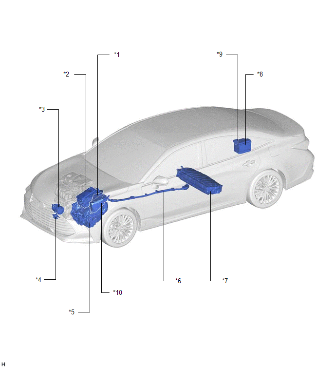
*1 | ECM |
*2 | INVERTER WITH CONVERTER ASSEMBLY |
|
*3 | COMPRESSOR WITH MOTOR ASSEMBLY |
*4 | INVERTER WATER PUMP ASSEMBLY |
|
*5 | HYBRID VEHICLE TRANSAXLE ASSEMBLY |
*6 | HV FLOOR UNDER WIRE |
|
*7 | HV BATTERY |
*8 | AUXILIARY BATTERY |
|
*9 | FUSIBLE LINK BLOCK ASSEMBLY - IGCT FUSE - ECU-B NO. 4 FUSE |
*10 | NO. 1 ENGINE ROOM RELAY BLOCK AND NO. 1 JUNCTION BLOCK ASSEMBLY - ECU-IG2 NO. 1 FUSE - IG2 NO. 1 RELAY - DC/DC FUSE - IG2-MAIN FUSE |
ILLUSTRATION
|
*1 | INVERTER WITH CONVERTER ASSEMBLY |
*2 | LOW VOLTAGE CONNECTOR |
|
*3 | AIR CONDITIONING WIRE CONNECTION |
*4 | HV FLOOR UNDER WIRE CONNECTION |
|
*5 | MOTOR CABLE CONNECTION |
*6 | INVERTER COVER - INTERLOCK |
|
*7 | AMD TERMINAL |
*8 | MOTOR CABLE |
|
*9 | HYBRID VEHICLE TRANSAXLE ASSEMBLY |
*10 | SHIFT LEVER POSITION SENSOR |
|
*11 | MOTOR TEMPERATURE SENSOR - GENERATOR TEMPERATURE SENSOR |
*12 | MOTOR RESOLVER - GENERATOR RESOLVER - TRANSMISSION FLUID TEMPERATURE SENSOR |
ILLUSTRATION
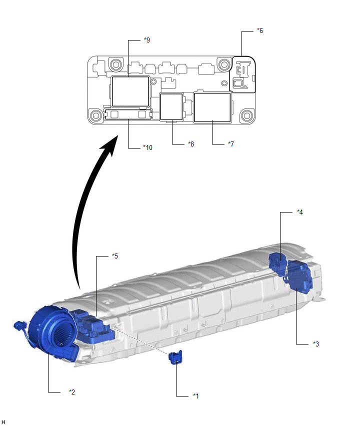
|
*1 | SERVICE PLUG GRIP |
*2 | BATTERY COOLING BLOWER ASSEMBLY |
|
*3 | BATTERY VOLTAGE SENSOR |
*4 | HYBRID BATTERY TERMINAL BLOCK |
|
*5 | HV BATTERY JUNCTION BLOCK ASSEMBLY |
*6 | BATTERY CURRENT SENSOR |
|
*7 | SMRB |
*8 | SMRP |
|
*9 | SMRG |
*10 | SYSTEM MAIN RESISTOR |
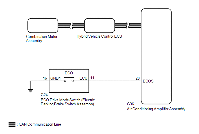
DESCRIPTION
When selecting ECO drive mode, the ECO drive mode switch (electric parking brake switch assembly) operation signal is sent to the air conditioning amplifier assembly. Following this, ECO drive mode control is activated for the heater and air conditioning system and the hybrid vehicle control system.
WIRING DIAGRAM
PROCEDURE
| 1. |
READ VALUE USING TECHSTREAM (CAN BUS CHECK) |
Click here 
|
Result | Proceed to |
|---|---|
|
All of the ECUs and sensors that are currently connected to the CAN communication system are displayed |
A |
| None of the ECUs and sensors that are currently connected to the CAN communication system are displayed, or some of them are not displayed |
B |
| B |
 | GO TO CAN COMMUNICATION SYSTEM |
|
| 2. |
CHECK DTC OUTPUT (HEALTH CHECK) |
Click here
|
Result | Proceed to |
|---|---|
|
No DTCs are output | A |
|
DTCs are output | B |
| B |
| GO TO DTC CHART |
|
| 3. |
READ VALUE USING TECHSTREAM (ECO SWITCH) |
(a) Connect the Techstream to the DLC3.
(b) Turn the power switch on (IG).
(c) Enter the following menus: Body Electrical / Air Conditioner / Data List / ECO Switch.
Body Electrical > Air Conditioner > Data List|
Tester Display |
|---|
| ECO Switch |
(d) Read the value displayed on the Techstream.
Body Electrical > Air Conditioner > Data List|
Tester Display | Measurement Item |
Range | Normal Condition |
|---|---|---|---|
|
ECO Switch | ECO drive mode switch condition |
ON or OFF | ECO drive mode switch being pushed and held: ON ECO drive mode switch not operated: OFF |
|
Result | Proceed to |
|---|---|
|
The Techstream display changes according to the ECO drive mode switch operation |
A |
| The Techstream display does not change according to the ECO drive mode switch operation |
B |
| A |
| REPLACE AIR CONDITIONING AMPLIFIER ASSEMBLY |
|
| 4. |
INSPECT ECO DRIVE MODE SWITCH (ELECTRIC PARKING BRAKE SWITCH ASSEMBLY) |
Click here
| NG | | REPLACE ELECTRIC PARKING BRAKE SWITCH ASSEMBLY |
|
| 5. |
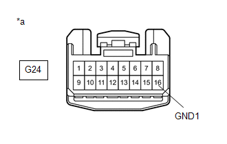
CHECK HARNESS AND CONNECTOR (ECO DRIVE MODE SWITCH (ELECTRIC PARKING BRAKE SWITCH ASSEMBLY) - BODY GROUND) |
(a) Disconnect the G24 ECO drive mode switch (electric parking brake switch assembly) connector.
| (b) Measure the resistance according to the value(s) in the table below. Standard Resistance:
|
|
(c) Reconnect the G24 ECO drive mode switch (electric parking brake switch assembly) connector.
| NG | | REPAIR OR REPLACE HARNESS OR CONNECTOR |
|
| 6. |
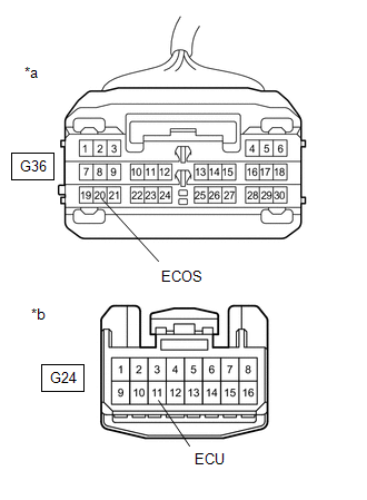
CHECK HARNESS AND CONNECTOR (AIR CONDITIONING AMPLIFIER ASSEMBLY - ECO DRIVE MODE SWITCH (ELECTRIC PARKING BRAKE SWITCH ASSEMBLY)) |
(a) Disconnect the G36 air conditioning amplifier assembly connector.
(b) Disconnect the G24 ECO drive mode switch (electric parking brake switch assembly) connector.
| (c) Measure the resistance according to the value(s) in the table below. Standard Resistance:
|
|
(d) Reconnect the G24 ECO drive mode switch (electric parking brake switch assembly) connector.
(e) Reconnect the G36 air conditioning amplifier assembly connector.
| OK | | REPLACE AIR CONDITIONING AMPLIFIER ASSEMBLY |
| NG | | REPAIR OR REPLACE HARNESS OR CONNECTOR |
Toyota Avalon (XX50) 2019-2022 Service & Repair Manual > Can Communication System(for Hv Model): Air Conditioning Amplifier Communication Stop Mode. ECU Malfunction (B1003). Blind Spot Monitor Sensor Communication Stop Mode
Air Conditioning Amplifier Communication Stop Mode DESCRIPTION Detection Item Symptom Trouble Area Air Conditioning Amplifier Communication Stop Mode Any of the following conditions are met: Communication stop for "Air Conditioning Amplifier" is indicated on the "Communication Bus Check" screen of t ...