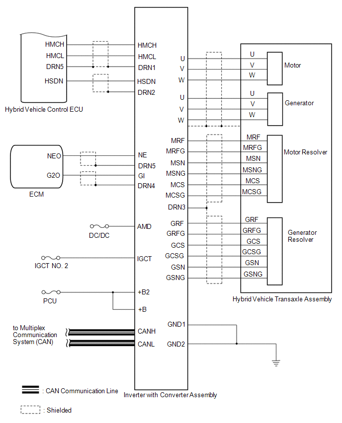
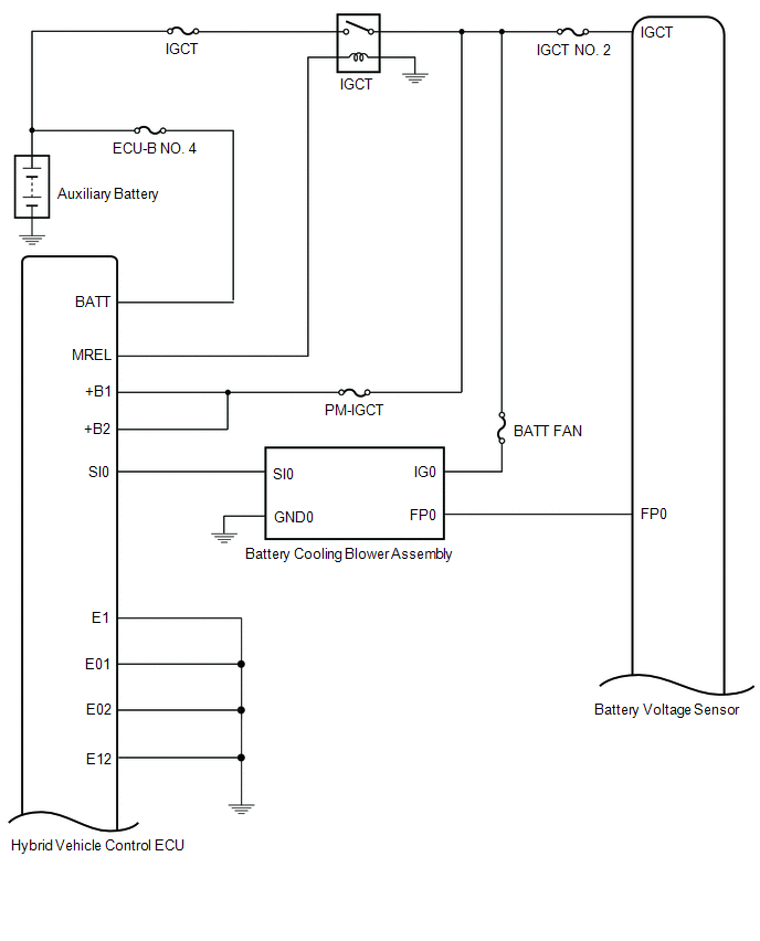
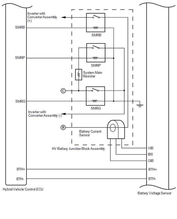
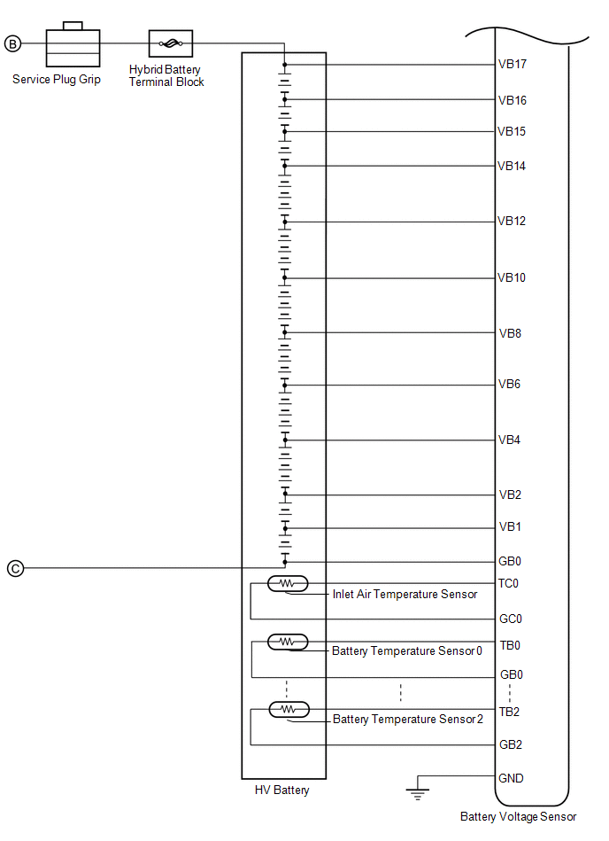
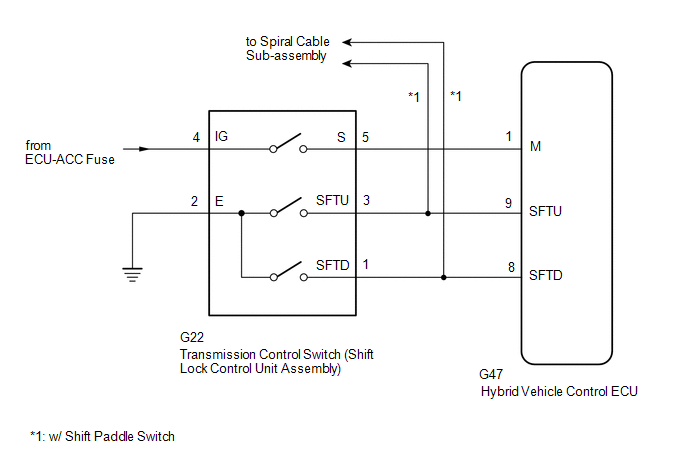
SYSTEM DIAGRAM
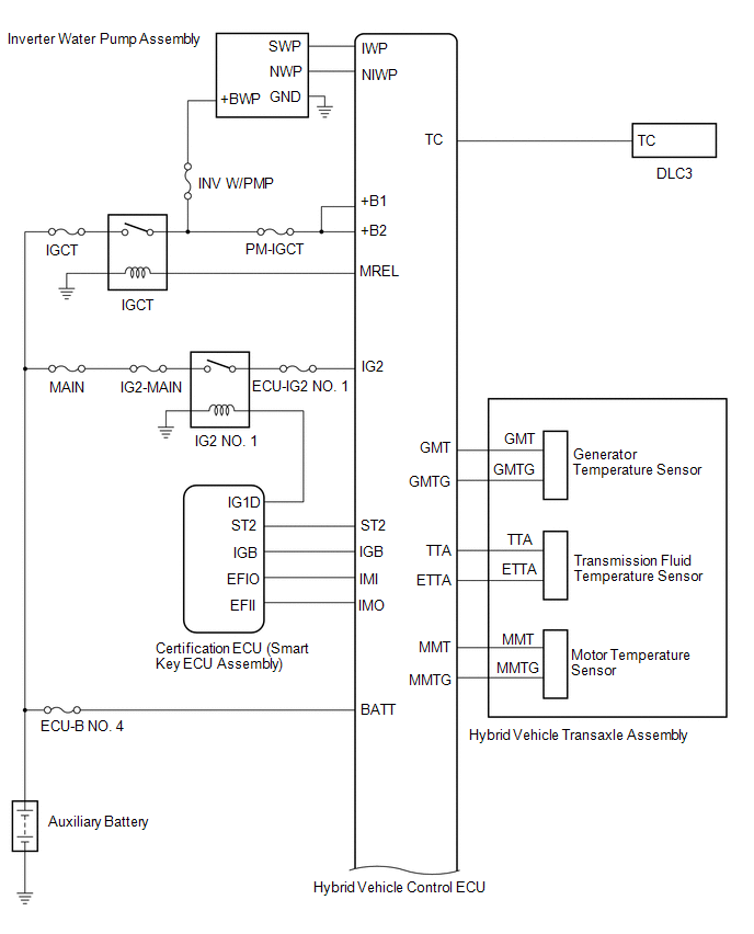
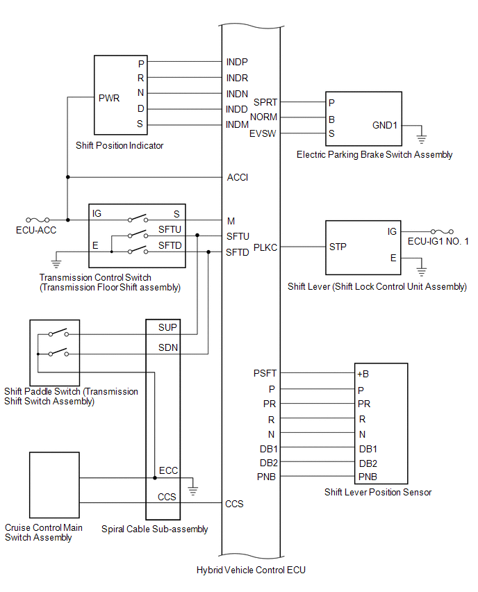
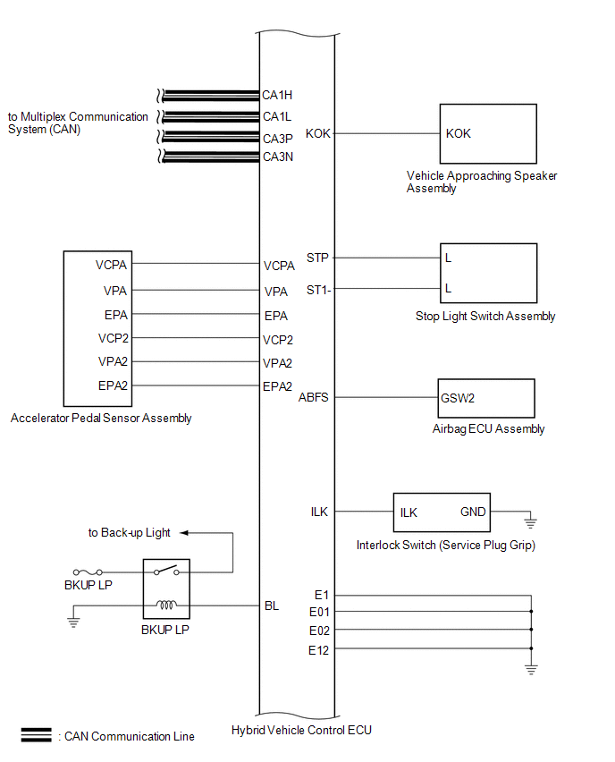
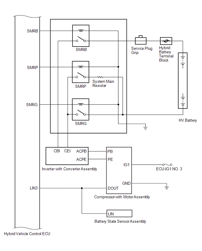
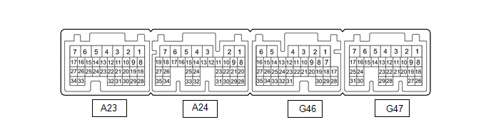
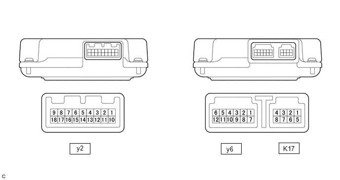
TERMINALS OF ECU
HYBRID VEHICLE CONTROL ECU
|
Terminal No. (Symbol) |
Wiring Color | Terminal Description |
Input/Output | Condition |
Specified Condition |
|---|---|---|---|---|---|
|
A23-1 (+B2) - G46-6 (E1) |
W - W-B | Power source |
Input | Power switch on (IG) |
11 to 14 V |
|
A23-3 (IG2) - G46-6 (E1) |
B - W-B | Power source |
Input | Power switch on (IG) |
11 to 14 V |
|
A23-8 (VCP2) - A23-18 (EPA2) |
SB - P | Accelerator pedal sensor assembly power source (for VPA2) |
Output | Power switch on (IG) |
4.5 to 5.5 V |
|
A23-9 (VCPA) - A23-20 (EPA) |
BE - L | Accelerator pedal sensor assembly power source (for VPA) |
Output | Power switch on (IG) |
4.5 to 5.5 V |
|
A23-13 (IWP) - G46-6 (E1) |
L - W-B | Inverter water pump with motor assembly signal |
Output | Power switch on (READY) |
Pulse generation (Waveform 1) |
|
A23-14 (NIWP) - G46-6 (E1) |
W - W-B | Inverter water pump with motor assembly signal |
Input | Power switch on (READY) |
Pulse generation (Waveform 1) |
|
A23-15 (STP) - G46-6 (E1) |
LA-G - W-B |
Stop light switch |
Input | Brake pedal depressed |
11 to 14 V |
| Brake pedal released |
0 to 1.5 V | ||||
|
A23-17 (LIN3) - G46-6 (E1) |
L - W-B | LIN communication signal (A/C inverter, auxiliary battery state sensor) |
Input/Output | Power switch on (READY) |
Pulse generation |
|
A23-21 (TTA) - A23-31 (ETTA) |
GR - SB | Transmission fluid temperature sensor |
Input | Power switch on (IG), temperature 25°C (77°F) |
3.6 to 4.6 V |
|
Power switch on (IG), temperature 60°C (140°F) |
2.2 to 3.2 V | ||||
|
A23-22 (ACCI) - G46-6 (E1) |
P - W-B | ACC relay |
Input | Power switch on (ACC) |
11 to 14 V |
|
A23-24 (MMT) - A23-23 (MMTG) |
G - R | Motor temperature sensor |
Input | Power switch on (IG), temperature 25°C (77°F) |
3.6 to 4.6 V |
|
Power switch on (IG), temperature 60°C (140°F) |
2.2 to 3.2 V | ||||
|
A23-26 (GMT) - A23-27 (GMTG) |
P - V | Generator temperature sensor |
Input | Power switch on (IG), temperature 25°C (77°F) |
3.6 to 4.6 V |
|
Power switch on (IG), temperature 60°C (140°F) |
2.2 to 3.2 V | ||||
|
A23-28 (VPA2) - A23-18 (EPA2) |
GR - P | Accelerator pedal sensor assembly (for accelerator pedal position detection) |
Input | Power switch on (IG), accelerator pedal released |
1.0 to 2.2 V |
|
Power switch on (IG), engine stopped, shift lever in P, accelerator pedal fully depressed |
3.4 to 5.3 V | ||||
|
A23-30 (VPA) - A23-20 (EPA) |
G - L | Accelerator pedal sensor assembly (for accelerator pedal position detection) |
Input | Power switch on (IG), accelerator pedal released |
0.4 to 1.4 V |
|
Power switch on (IG), engine stopped, shift lever in P, accelerator pedal fully depressed |
2.6 to 4.5 V | ||||
|
A24-1 (PSFT) - G46-6 (E1) |
L - W-B | Shift lever position sensor power source |
Output | Power switch on (ACC) |
7.5 to 14 V |
|
A24-2 (BL) - G46-6 (E1) |
BE - W-B | Back-up light |
Output | Power switch on (IG), shift lever in R |
11 to 14 V |
|
A24-4 (+B1) - G46-6 (E1) |
R - W-B | Power source |
Input | Power switch on (IG) |
11 to 14 V |
|
A24-6 (MREL) - G46-6 (E1) |
G - W-B | Main relay |
Output | Power switch on (IG) |
11 to 14 V |
|
A24-7 (IGB) - G46-6 (E1) |
B - W-B | Power source |
Input | Power switch on (IG) |
8.5 to 14 V |
|
A24-12 (HSDN) - G46-6 (E1) |
W - W-B | MG ECU shutdown signal |
Output | Power switch on (READY) |
0 to 1.5 V |
|
A24-13 (ILK) - G46-6 (E1) |
GR - W-B | Interlock switch |
Input | Power switch on (IG), service plug grip installed correctly |
0 to 1.5 V |
| Power switch on (IG), service plug grip not installed |
11 to 14 V | ||||
|
A24-14 (DB2) - G46-6 (E1) |
V - W-B | Shift lever position signal |
Input | Power switch on (IG), shift lever in D or S |
7.5 to 14 V |
|
Power switch on (IG), shift lever not in D or S |
0 to 1.5 V | ||||
|
A24-15 (R) - G46-6 (E1) |
LG - W-B | Shift lever position signal |
Input | Power switch on (IG), shift lever in R |
7.5 to 14 V |
|
Power switch on (IG), shift lever not in R |
0 to 1.5 V | ||||
|
A24-17 (PR) - G46-6 (E1) |
R - W-B | Shift lever position signal |
Input | Power switch on (IG), shift lever in P or R |
7.5 to 14 V |
|
Power switch on (IG), shift lever not in P or R |
0 to 1.5 V | ||||
|
A24-20 (N) - G46-6 (E1) |
G - W-B | Shift lever position signal |
Input | Power switch on (IG), shift lever in N |
7.5 to 14 V |
|
Power switch on (IG), shift lever not in N |
0 to 1.5 V | ||||
|
A24-21 (P) - G46-6 (E1) |
BE - W-B | Shift lever position signal |
Input | Power switch on (IG), shift lever in P |
7.5 to 14 V |
|
Power switch on (IG), shift lever not in P |
0 to 1.5 V | ||||
|
A24-26 (DB1) - G46-6 (E1) |
W - W-B | Shift lever position signal |
Input | Power switch on (IG), shift lever in D or S |
7.5 to 14 V |
|
Power switch on (IG), shift lever not in D or S |
0 to 1.5 V | ||||
|
A24-28 (ST1-) - G46-6 (E1) |
LG - W-B | Stop light switch signal |
Input | Power switch on (IG), brake pedal depressed |
0 to 1.5 V |
| Power switch on (IG), brake pedal released |
11 to 14 V | ||||
|
A24-30 (HMCL) - G46-6 (E1) |
W - W-B | MG ECU communication request signal |
Input/Output | Power switch on (IG) |
Pulse generation (Waveform 2) |
|
A24-31 (HMCH) - G46-6 (E1) |
B - W-B | MG ECU communication request signal |
Input/Output | Power switch on (IG) |
Pulse generation (Waveform 2) |
|
A24-34 (PNB) - G46-6 (E1) |
B - W-B | Shift lever position signal |
Input | Power switch on (IG), shift lever in P or N |
7.5 to 14 V |
|
G46-1 (SMRG) - G46-5 (E01) |
G - W-B | System main relay operation signal |
Output | Power switch on (IG) → Power switch on (READY) |
Pulse generation (Waveform 3) |
|
G46-3 (SMRP) - G46-5 (E01) |
W - W-B | System main relay operation signal |
Output | Power switch on (IG) → Power switch on (READY) |
Pulse generation (Waveform 3) |
|
G46-4 (SMRB) - G46-5 (E01) |
GR - W-B | System main relay operation signal |
Output | Power switch on (IG) → Power switch on (READY) |
Pulse generation (Waveform 3) |
|
G46-7 (KOK) - G46-6 (E1) |
BE - W-B | Vehicle proximity notification system permission signal |
Output | Power switch on (IG) |
0 to 2.0 V |
|
G46-8 (INDR) - G46-6 (E1) |
LG - W-B | Shift position indicator signal |
Input | Power switch on (IG), shift lever in R |
0 to 3.2 V |
| Power switch on (IG), shift lever not in R |
11 to 14 V | ||||
|
G46-9 (ST2) - G46-6 (E1) |
L - W-B | Starter signal |
Input | Power switch on (IG) |
0 to 1.5 V |
|
G46-10 (NORM) ←→ G46-6(E1) |
LG - W-B | Normal mode switch (electric parking brake switch assembly) signal |
Input | Power switch on (IG), normal mode switch (electric parking brake switch assembly) not operated |
11 to 14 V |
| Power switch on (IG), normal mode switch (electric parking brake switch assembly) operated |
0 to 1.5 V | ||||
|
G46-32 (BTH+) - G46-6 (E1) |
LG - W-B | Communication signal from battery voltage sensor to hybrid vehicle control ECU |
Input | Power switch on (IG) |
Pulse generation (Waveform 4) |
|
G46-33 (BTH-) - G46-6 (E1) |
W - W-B | Communication signal from battery voltage sensor to hybrid vehicle control ECU |
Input | Power switch on (IG) |
Pulse generation (Waveform 4) |
|
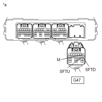
G47-1 (M) - G46-6 (E1) |
B - W-B | Transmission control |
Input | Power switch on (IG), shift lever in S |
11 to 14 V |
| Power switch on (IG), shift lever not in S |
0 to 1.5 V | ||||
|
G47-3 (BATT) - G46-6 (E1) |
B - W-B | Constant power source |
Input | Power switch on (IG) |
11 to 14 V |
| Power switch on (READY) |
11 to 15.5 V | ||||
|
G47-6 (SPRT) - G46-6 (E1) |
R - W-B | Sport mode switch (electric parking brake switch assembly) signal |
Input | Power switch on (IG), sport mode switch (electric parking brake switch assembly) not operated |
11 to 14 V |
| Power switch on (IG), sport mode switch (electric parking brake switch assembly) operated |
0 to 1.5 V | ||||
|
G47-7 (PLKC) - G46-6 (E1) |
L - W-B | Shift lock release request signal |
Output | Power switch on (READY), brake pedal depressed |
11 to 14 V |
| Power switch on (READY), brake pedal released |
0 to 1.5 V | ||||
|
G47-8 (SFTD) - G46-6 (E1) |
W - W-B | Transmission control |
Input | Power switch on (IG), shift lever in S |
11 to 14 V |
| Power switch on (IG), shift lever in (-) or shift paddle switch LH (-) operated |
0 to 1.5 V | ||||
|
G47-9 (SFTU) - G46-6 (E1) |
LG - W-B | Transmission control |
Input | Power switch on (IG), shift lever in S |
11 to 14 V |
| Power switch on (IG), shift lever in (+) or shift paddle switch RH (+) operated |
0 to 1.5 V | ||||
|
G47-10 (INDM) - G46-6 (E1) |
GR - W-B | Shift position indicator signal |
Input | Power switch on (IG), shift lever in S |
0 to 3.2 V |
| Power switch on (IG), shift lever not in S |
11 to 14 V | ||||
|
G47-11 (INDD) - G46-6 (E1) |
W - W-B | Shift position indicator signal |
Input | Power switch on (IG), shift lever in D |
0 to 3.2 V |
| Power switch on (IG), shift lever not in D |
11 to 14 V | ||||
|
G47-12 (INDN) - G46-6 (E1) |
R - W-B | Shift position indicator signal |
Input | Power switch on (IG), shift lever in N |
0 to 3.2 V |
| Power switch on (IG), shift lever not in N |
11 to 14 V | ||||
|
G47-13 (INDP) - G46-6 (E1) |
L - W-B | Shift position indicator signal |
Input | Power switch on (IG), shift lever in P |
0 to 3.2 V |
| Power switch on (IG), shift lever not in P |
11 to 14 V | ||||
|
G47-14 (ABFS) - G46-6 (E1) |
B - W-B | Airbag activation signal |
Input | Power switch on (READY) |
Pulse generation (Waveform 5) |
|
G47-15 (EVSW) - G46-6 (E1) |
G - W-B | EV drive mode switch (electric parking brake switch assembly) signal |
Input | Power switch on (IG), EV drive mode switch (electric parking brake switch assembly) not operated |
11 to 14 V |
| Power switch on (IG), EV drive mode switch (electric parking brake switch assembly) operated |
0 to 1.5 V | ||||
|
G47-24 (CA1L) - G46-6 (E1) |
W - W-B | CAN communication signal |
Input/Output | Power switch on (IG) |
Pulse generation (Waveform 6) |
|
G47-25 (CA1H) - G46-6 (E1) |
L - W-B | CAN communication signal |
Input/Output | Power switch on (IG) |
Pulse generation (Waveform 6) |
|
G47-28 (TC) - G46-6 (E1) |
GR - W-B | Diagnosis terminal |
Input | Power switch on (IG) |
11 to 14 V |
|
G47-29 (SI0) - G46-6 (E1) |
L - W-B | HV battery cooling blower assembly operation signal |
Output | Cooling fans operating |
Pulse generation (Waveform 7) |
|
Cooling fans not operating |
4.5 to 5.5 V | ||||
|
G47-30 (CA3N) - G46-6 (E1) |
W - W-B | CAN communication signal |
Input/Output | Power switch on (IG) |
Pulse generation (Waveform 8) |
|
G47-31 (CA3P) - G46-6 (E1) |
G - W-B | CAN communication signal |
Input/Output | Power switch on (IG) |
Pulse generation (Waveform 8) |
(a) Oscilloscope waveforms
HINT:
Oscilloscope waveform samples are provided here for informational purposes. Noise and fluttering waveforms have been omitted.
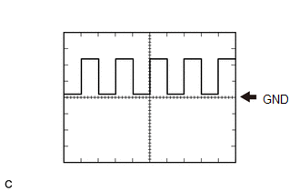
(1) Waveform 1 (Inverter water pump assembly signal)
|
Item | Content |
|---|---|
|
Terminal | CH1: A23-13 (IWP) - G46-6 (E1) CH2: A23-14 (NIWP) - G46-6 (E1) |
|
Equipment Setting | 5 V/DIV., 20 ms./DIV. |
|
Condition | Power switch on (READY) |
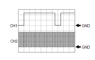
HINT:
The duty of the IWP signal and the frequency of the NIWP signal change according to the coolant (for inverter) temperature.
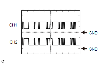
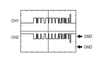
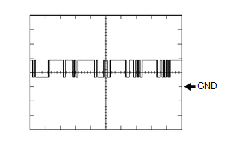
(2) Waveform 2 (MG ECU communication signal)
|
Item | Content |
|---|---|
|
Terminal | CH1: A24-31 (HMCH) - G46-6 (E1) CH2: A24-30 (HMCL) - G46-6 (E1) |
|
Equipment Setting | 1 V/DIV., 50 μs./DIV. |
|
Condition | Power switch on (IG) |
HINT:
The waveform will vary depending on the content of the digital communication (digital signal).

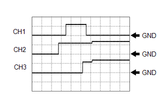
(3) Waveform 3 (System main relay operation signal)
|
Item | Content |
|---|---|
|
Terminal | CH1: G46-3 (SMRP) - G46-5 (E01) CH2: G46-4 (SMRB) - G46-5 (E01) CH3: G46-1 (SMRG) - G46-5 (E01) |
|
Equipment Setting | 10 V/DIV., 200 ms./DIV. |
|
Condition | Power switch on (IG) → Power switch on (READY) |
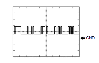
(4) Waveform 4 (Communication signal from battery voltage sensor to hybrid vehicle control ECU)
|
Item | Content |
|---|---|
|
Terminal | CH1: G46-32 (BTH+) - G46-6 (E1) CH2: G46-33 (BTH-) - G46-6 (E1) |
|
Equipment Setting | 2 V/DIV., 500 μs./DIV. |
|
Condition | Power switch on (IG) |
HINT:
The waveform will vary depending on the content of the digital communication (digital signal).
(5) Waveform 5 (Airbag activation signal)
|
Item | Content |
|---|---|
|
Terminal | G47-14 (ABFS) - G46-6 (E1) |
|
Equipment Setting | 5 V/DIV., 150 ms./DIV. |
|
Condition | Power switch on (READY) |
(6) Waveform 6 (CAN communication signal)
|
Item | Content |
|---|---|
|
Terminal | CH1: G47-25 (CA1H) - G46-6 (E1) CH2: G47-24 (CA1L) - G46-6 (E1) |
|
Equipment Setting | 1 V/DIV., 50 μs./DIV. |
|
Condition | Power switch on (IG) |
HINT:
The waveform will vary depending on the content of the digital communication (digital signal).
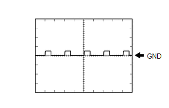
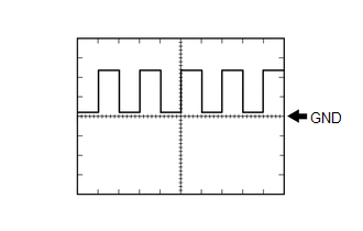
(7) Waveform 7 (HV battery blower fan operation signal)
|
Item | Content |
|---|---|
|
Terminal | G47-29 (SI0) - G46-6 (E1) |
|
Equipment Setting | 10 V/DIV., 1 ms./DIV. |
|
Condition | Cooling fans operating |
HINT:
The waveform will vary with the operating speed of the battery cooling blower assembly.
(8) Waveform 8 (CAN communication signal)
|
Item | Content |
|---|---|
|
Terminal | CH1: G47-31 (CA3P) - G46-6 (E1) CH2: G47-30 (CA3N) - G46-6 (E1) |
|
Equipment Setting | 1 V/DIV., 50 μs./DIV. |
|
Condition | Power switch on (IG) |
HINT:
The waveform will vary depending on the content of the digital communication (digital signal).

BATTERY VOLTAGE SENSOR
|
Terminal No. (Symbol) |
Wiring Color | Input/Output |
Terminal Description | Condition |
Specified Condition |
|---|---|---|---|---|---|
|
y6-1 (TC0) - y6-7 (GC0) |
G - G | IN |
Intake air temperature sensor |
Power switch on (IG), HV battery intake air temperature: -40 to 90°C (-40 to 194°F) |
4.8 (-40°C (-40°F)) to 1.0 V (90°C (194°F)) |
|
y6-2 (TB2) - y6-8 (GB2) |
R - R | IN |
Battery temperature sensor 2 | Power switch on (IG), HV battery temperature: -40 to 90°C (-40 to 194°F) |
4.8 (-40°C (-40°F)) to 1.0 V (90°C (194°F)) |
|
y6-3 (TB1) - y6-9 (GB1) |
W - W | IN |
Battery temperature sensor 1 | Power switch on (IG), HV battery temperature: -40 to 90°C (-40 to 194°F) |
4.8 (-40°C (-40°F)) to 1.0 V (90°C (194°F)) |
|
y6-4 (TB0) - y6-10 (GB0) |
L - L | IN |
Battery temperature sensor 0 | Power switch on (IG),, HV battery temperature: -40 to 90°C (-40 to 194°F) |
4.8 (-40°C (-40°F)) to 1.0 V (90°C (194°F)) |
|
y6-5 (IB0) - y6-12 (GIB) |
Y - B | IN |
Battery current sensor | Power switch on (IG) |
0.5 to 4.5 V |
|
y6-6 (VIB) - y6-12 (GIB) |
BR - B | OUT |
Power source for battery current sensor |
Power switch on (IG) |
4.5 to 5.5 V |
|
K17-1 (IGCT) - K17-5 (GND) |
BE - W-B | IN |
Control signal | Power switch on (IG) |
11 to 14 V |
|
K17-2 (BTH+) - K17-5 (GND) |
GR - W-B | OUT |
Serial communication | Power switch on (IG) |
Pulse generation (waveform 1) |
|
K17-3 (BTH-) - K17-5 (GND) |
W - W-B | OUT |
Serial communication | Power switch on (IG) |
Pulse generation (waveform 2) |
|
K17-5 (GND) - Body ground |
W-B | - |
Ground | Always (continuity check) |
Below 1 Ω |
|
K17-8 (FP0) - K17-5 (GND) |
B - W-B | IN |
Battery cooling blower monitor signal |
Battery cooling blower assembly stopped |
0 Hz |
| Battery cooling blower assembly operating (Active Test of cooling fan being performed) |
Pulse generation (waveform 3) |
(a) Oscilloscope waveforms
HINT:
Oscilloscope waveform samples are provided here for informational purposes. Noise and fluttering waveforms have been omitted.
(1) Waveform 1 (Serial communication)
|
Item | Content |
|---|---|
|
Terminal | K17-2 (BTH+) - K17-5 (GND) |
|
Equipment Setting | 2 V/DIV., 500 μs/DIV. |
|
Condition | Power switch on (IG) |
HINT:
The waveform will vary depending on the content of the digital communication (digital signal).
(2) Waveform 2 (Serial communication)
|
Item | Content |
|---|---|
|
Terminal | K17-3 (BTH-) - K17-5 (GND) |
|
Equipment Setting | 2 V/DIV., 500 μs/DIV. |
|
Condition | Power switch on (IG) |
HINT:
The waveform will vary depending on the content of the digital communication (digital signal).
(3) Waveform 3 (Battery cooling blower monitor signal)
|
Item | Content |
|---|---|
|
Terminal | K17-8 (FP0) - K17-5 (GND) |
|
Equipment Setting | 2 V/DIV., 2 ms/DIV. |
|
Condition | Battery cooling blower assembly operating (Active Test of cooling fan being performed) |
HINT:
The frequency of the waveform will vary with the operating speed of the battery cooling blower assembly.
DESCRIPTION
When the shift lever is in S, different ranges can be chosen using the floor shift sequential gate.
WIRING DIAGRAM
Refer to the wiring diagram for the shift paddle switch circuit. (w/ Shift paddle switch)
Click here 
PROCEDURE
| 1. |
READ VALUE USING TECHSTREAM (SPORTS SHIFT POSITION) |
(a) Connect the Techstream to the DLC3.
(b) Turn the power switch on (IG).
(c) Enter the following menus: Powertrain / Hybrid Control / Data List / Sports Shift Position.
Powertrain > Hybrid Control > Data List|
Tester Display |
|---|
| Sports Shift Position |
(d) Read the value displayed on the Techstream.
Powertrain > Hybrid Control > Data List|
Tester Display | Measurement Item |
Range | Normal Condition |
|---|---|---|---|
|
Sports Shift Position | Sports shift position |
Min.: 0, Max.: 255 | Shift lever in S (1): 0 Shift lever in S (2): 1 Shift lever in S (3): 2 Shift lever in S (4): 3 Shift lever in S (5): 4 Shift lever in S (6): 5 Shift lever in any position other than S: 255 |
|
Result | Proceed to |
|---|---|
|
The Techstream display changes according to the shift lever operation. |
A |
| The Techstream display does not change according to the shift lever operation. |
B |
(e) Turn the power switch off.
| B |
 | GO TO STEP 4 |
|
| 2. |
READ VALUE USING TECHSTREAM (SPORTS SHIFT UP SIGNAL, SPORTS SHIFT DOWN SIGNAL) |
(a) Connect the Techstream to the DLC3.
(b) Turn the power switch on (IG).
(c) Enter the following menus: Powertrain / Hybrid Control / Data List / Sports Shift UP Signal, Sports Shift DOWN Signal.
Powertrain > Hybrid Control > Data List|
Tester Display |
|---|
| Sports Shift UP Signal |
|
Sports Shift DOWN Signal |
(d) Read the value displayed on the Techstream.
Powertrain > Hybrid Control > Data List|
Tester Display | Measurement Item |
Range | Normal Condition |
|---|---|---|---|
|
Sports Shift UP Signal |
Operation of "+" transmission control switch. |
ON or OFF | Shift lever held in "+" operated: ON Shift lever not operated: OFF |
|
Sports Shift DOWN Signal |
Operation of "-" transmission control switch. |
ON or OFF | Shift lever held in "-" operated: ON Shift lever not operated: OFF |
|
Result | Proceed to |
|---|---|
|
The Techstream display changes according to the transmission control switch (shift lock control unit assembly) operation |
A |
| The Techstream display does not change according to the transmission control switch (shift lock control unit assembly) operation |
B |
(e) Turn the power switch off.
| B |
| GO TO STEP 7 |
|
| 3. |
CHECK FOR INTERMITTENT PROBLEMS |
Click here
| OK | |
REPLACE HYBRID VEHICLE CONTROL ECU |
| NG | | REPAIR OR REPLACE MALFUNCTIONING PARTS, COMPONENT AND AREA |
| 4. |
CHECK HARNESS AND CONNECTOR (POWER SOURCE CIRCUIT) |
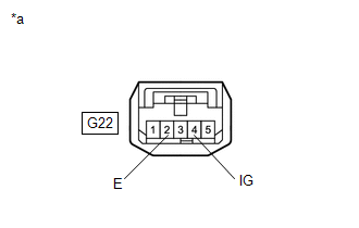
(a) Disconnect the G22 transmission control switch (shift lock control unit assembly) connector.
(b) Turn the power switch on (IG).
| (c) Measure the voltage according to the value(s) in the table below. Standard Voltage:
|
|
(d) Turn the power switch off.
(e) Measure the voltage according to the value(s) in the table below.
Standard Voltage:
|
Tester Connection | Condition |
Specified Condition |
|---|---|---|
| G22-4 (IG) - Body ground |
Power switch off | Below 1 V |
(f) Measure the resistance according to the value(s) in the table below.
Standard Resistance:
|
Tester Connection | Condition |
Specified Condition |
|---|---|---|
|
G22-2 (E) - Body ground |
Power switch off | Below 1 Ω |
(g) Reconnect the G22 transmission control switch (shift lock control unit assembly) connector.
| NG | | CHECK POWER SOURCE CIRCUIT |
|
| 5. |
INSPECT TRANSMISSION CONTROL SWITCH (SHIFT LOCK CONTROL UNIT ASSEMBLY) |
(a) Inspect the transmission control switch (shift lock control unit assembly).
Click here
| NG | | REPLACE SHIFT LOCK CONTROL UNIT ASSEMBLY |
|
| 6. |
CHECK HARNESS AND CONNECTOR (HYBRID VEHICLE CONTROL ECU - TRANSMISSION CONTROL SWITCH (SHIFT LOCK CONTROL UNIT ASSEMBLY)) |
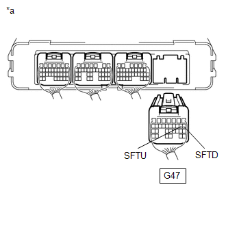
| (a) Disconnect the G47 hybrid vehicle control ECU connector. |
|
(b) Disconnect the G17 spiral cable sub-assembly connector. (w/ Shift paddle switch)
(c) Turn the power switch on (IG).
(d) Measure the voltage according to the value(s) in the table below when the shift lever is moved to each position.
Standard Voltage:
|
Tester Connection | Condition |
Specified Condition |
|---|---|---|
|
G47-1 (M) - Body ground |
Power switch on (IG) Shift lever in S, "+" or "-" |
11 to 14 V |
|
Power switch on (IG) Except shift lever in S, "+" and "-" |
Below 1 V |
NOTICE:
If the power switch is turned on (IG) with the hybrid vehicle control ECU connector disconnected, other DTCs will be stored. After performing the inspection, clear the DTCs.
(e) Turn the power switch off.
(f) Measure the resistance according to the value(s) in the table below when the shift lever is moved to each position.
Standard Resistance:
|
Tester Connection | Condition |
Specified Condition |
|---|---|---|
|
G47-9 (SFTU) - Body ground |
Shift lever held in "+" |
Below 13 Ω |
| G47-9 (SFTU) - Body ground |
Shift lever not operated |
10 kΩ or higher |
|
G47-8 (SFTD) - Body ground |
Shift lever held in "-" |
Below 13 Ω |
| G47-8 (SFTD) - Body ground |
Shift lever not operated |
10 kΩ or higher |
(g) Reconnect the G17 spiral cable sub-assembly connector. (w/ Shift paddle switch)
(h) Reconnect the G47 hybrid vehicle control ECU connector.
| OK | | REPLACE HYBRID VEHICLE CONTROL ECU |
| NG | | REPAIR OR REPLACE HARNESS OR CONNECTOR |
| 7. |
INSPECT TRANSMISSION CONTROL SWITCH (SHIFT LOCK CONTROL UNIT ASSEMBLY) |
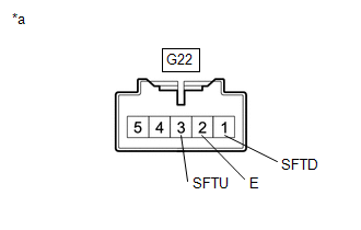
(a) Disconnect the G22 transmission control switch (shift lock control unit assembly) connector.
| (b) Measure the resistance according to the value(s) in the table below when the shift lever is moved to each position. Standard Resistance:
|
|
(c) Reconnect the G22 transmission control switch (shift lock control unit assembly) connector.
| NG | | REPLACE SHIFT LOCK CONTROL UNIT ASSEMBLY |
|
| 8. |
CHECK HARNESS AND CONNECTOR (TRANSMISSION CONTROL SWITCH (SHIFT LOCK CONTROL UNIT ASSEMBLY) - HYBRID VEHICLE CONTROL ECU) |
(a) Disconnect the G47 hybrid vehicle control ECU connector.
(b) Disconnect the G17 spiral cable sub-assembly connector. (w/ Shift paddle switch)
| (c) Measure the resistance according to the value(s) in the table below when the shift lever is moved to each position. Standard Resistance:
|
|
(d) Reconnect the G17 spiral cable sub-assembly connector. (w/ Shift paddle switch)
(e) Reconnect the G47 hybrid vehicle control ECU connector.
| OK | | REPLACE HYBRID VEHICLE CONTROL ECU |
| NG | | REPAIR OR REPLACE HARNESS OR CONNECTOR |
Toyota Avalon (XX50) 2019-2022 Service & Repair Manual > Lighting (int): Door Courtesy Light
ComponentsCOMPONENTS ILLUSTRATION *1 COURTESY LIGHT ASSEMBLY *2 COURTESY LIGHT BULB *3 COURTESY LIGHT LENS *4 COURTESY LIGHT COVER *5 COURTESY LIGHT HOUSING - - InspectionINSPECTION PROCEDURE 1. INSPECT COURTESY LIGHT ASSEMBLY *a Component without harness connected (Courtesy Light Assembly) (a) App ...