|
DTC No. | Detection Item |
Order of Priority |
Inspection Pattern |
|
1 | 2 |
3 | 4 |
5 |
| Microcomputer Malfunction |
Power Source Circuit Malfunction |
Communication System Malfunction |
Sensor and Actuator Circuit Malfunction |
System Malfunction |
|
P033500 | Crankshaft Position Sensor "A" |
- | - |
- | ○ |
- | - |
|
P033531 | Crankshaft Position Sensor "A" No Signal |
- | - |
- | ○ |
- | - |
|
P034000 | Camshaft Position Sensor "A" Circuit Bank 1 or Single Sensor |
- | - |
- | ○ |
- | - |
|
P034031 | Camshaft Position Sensor "A" Circuit Bank 1 or Single Sensor No Signal |
- | - |
- | ○ |
- | - |
|
P062F44 | Internal Control Module EEPROM Data Memory Failure |
○ | - |
- | - |
- | - |
|
P062F46 | Generator Control Module (EEPROM Learning Value) Calibration / Parameter Memory Failure |
○ | - |
- | - |
- | - |
|
P06B01C | Generator Control Module Position Sensor REF Power Source Circuit Voltage Out of Range |
- | ○ |
- | - |
- | - |
|
P06D61C | Generator Control Module Offset Power Circuit Voltage Out of Range |
- | ○ |
- | - |
- | - |
|
P0A0011 | Motor Electronics Coolant Temperature Sensor Circuit Short to Ground |
- | - |
- | ○ |
- | - |
|
P0A0015 | Motor Electronics Coolant Temperature Sensor Circuit Short to Battery or Open |
- | - |
- | ○ |
- | - |
|
P0A001C | Motor Electronics Coolant Temperature Sensor Circuit Voltage Out of Range |
- | - |
- | ○ |
- | B |
|
P0A0812 | DC/DC Converter Status Circuit Short to Battery |
- | - |
- | ○ |
- | A |
|
P0A0814 | DC/DC Converter Status Circuit Short to Ground or Open |
- | - |
- | ○ |
- | A |
|
P0A1112 | DC/DC Converter Enable Circuit Short to Battery |
- | - |
- | ○ |
- | A |
|
P0A1114 | DC/DC Converter Enable Circuit Short to Ground or Open |
- | - |
- | ○ |
- | A |
|
P0A1A47 | Generator Control Module Watchdog / Safety μC Failure |
○ | - |
- | - |
- | - |
|
P0A1A49 | Generator Control Module Internal Electronic Failure |
○ | - |
- | - |
- | - |
|
P0A1B1F | Generator Control Module Circuit Intermittent |
○ | - |
- | - |
- | - |
|
P0A3F16 | Drive Motor "A" Position Sensor Circuit Voltage Below Threshold |
- | - |
- | ○ |
- | G |
|
P0A3F1F | Drive Motor "A" Position Sensor Circuit Intermittent |
- | - |
- | ○ |
- | G |
|
P0A3F21 | Drive Motor "A" Position Sensor Signal Amplitude < Minimum |
- | - |
- | ○ |
- | G |
|
P0A3F22 | Drive Motor "A" Position Sensor Signal Amplitude > Maximum |
- | - |
- | ○ |
- | G |
|
P0A4B16 | Generator Position Sensor Circuit Voltage Below Threshold |
- | - |
- | ○ |
- | I |
|
P0A4B1F | Generator Position Sensor Circuit Intermittent |
- | - |
- | ○ |
- | I |
|
P0A4B21 | Generator Position Sensor Signal Amplitude < Minimum |
- | - |
- | ○ |
- | I |
|
P0A4B22 | Generator Position Sensor Signal Amplitude > Maximum |
- | - |
- | ○ |
- | I |
|
P0A6012 | Drive Motor "A" Phase V Current (High Resolution) Circuit Short to Battery |
- | - |
- | ○ |
- | A |
|
P0A6014 | Drive Motor "A" Phase V Current (High Resolution) Circuit Short to Ground or Open |
- | - |
- | ○ |
- | A |
|
P0A601C | Drive Motor "A" Phase V Current (High Resolution) Circuit Voltage Out of Range |
- | - |
- | ○ |
- | A |
|
P0A601F | Drive Motor "A" Phase V Current (High Resolution) Circuit Intermittent |
- | - |
- | ○ |
- | A |
|
P0A6312 | Drive Motor "A" Phase W Current (High Resolution) Circuit Short to Battery |
- | - |
- | ○ |
- | A |
|
P0A6314 | Drive Motor "A" Phase W Current (High Resolution) Circuit Short to Ground or Open |
- | - |
- | ○ |
- | A |
|
P0A631C | Drive Motor "A" Phase W Current (High Resolution) Circuit Voltage Out of Range |
- | - |
- | ○ |
- | A |
|
P0A631F | Drive Motor "A" Phase W Current (High Resolution) Circuit Intermittent |
- | - |
- | ○ |
- | A |
|
P0A7872 | Drive Motor "A" Inverter Actuator Stuck Open |
- | - |
- | - |
○ | A |
|
P0A7873 | Drive Motor "A" Inverter Actuator Stuck Closed |
- | - |
- | - |
○ | - |
|
P0A789E | Drive Motor "A" Inverter Stuck On |
- | - |
- | - |
○ | E |
|
P0A7A72 | Generator Inverter Actuator Stuck Open |
- | - |
- | - |
○ | A |
|
P0A7A73 | Generator Inverter Actuator Stuck Closed |
- | - |
- | - |
○ | - |
|
P0A7A9E | Generator Inverter Stuck On |
- | - |
- | - |
○ | E |
|
P0A9000 | Drive Motor "A" Performance |
- | - |
- | - |
○ | H |
|
P0A9200 | Hybrid Generator Performance |
- | - |
- | - |
○ | J |
|
P0A949E | DC/DC Converter Stuck On |
- | - |
- | - |
○ | E |
|
P0AED11 | Drive Motor Inverter Temperature Sensor "A" Circuit Short to Ground |
- | - |
- | ○ |
- | - |
|
P0AED15 | Drive Motor Inverter Temperature Sensor "A" Circuit Short to Battery or Open |
- | - |
- | ○ |
- | - |
|
P0AED1C | Drive Motor Inverter Temperature Sensor "A" Circuit Voltage Out of Range |
- | - |
- | ○ |
- | B |
|
P0BE512 | Drive Motor "A" Phase U Current Sensor Circuit Short to Battery |
- | - |
- | ○ |
- | A |
|
P0BE514 | Drive Motor "A" Phase U Current Sensor Circuit Short to Ground or Open |
- | - |
- | ○ |
- | A |
|
P0BE51F | Drive Motor "A" Phase U Current Sensor Circuit Intermittent |
- | - |
- | ○ |
- | A |
|
P0BE528 | Drive Motor "A" Phase U Current Sensor Signal Bias Level Out of Range / Zero Adjustment Failure |
- | - |
- | ○ |
- | A |
|
P0BE912 | Drive Motor "A" Phase V Current Sensor Circuit Short to Battery |
- | - |
- | ○ |
- | A |
|
P0BE914 | Drive Motor "A" Phase V Current Sensor Circuit Short to Ground or Open |
- | - |
- | ○ |
- | A |
|
P0BE91F | Drive Motor "A" Phase V Current Sensor Circuit Intermittent |
- | - |
- | ○ |
- | A |
|
P0BE928 | Drive Motor "A" Phase V Current Sensor Signal Bias Level Out of Range / Zero Adjustment Failure |
- | - |
- | ○ |
- | A |
|
P0BED12 | Drive Motor "A" Phase W Current Sensor Circuit Short to Battery |
- | - |
- | ○ |
- | A |
|
P0BED14 | Drive Motor "A" Phase W Current Sensor Circuit Short to Ground or Open |
- | - |
- | ○ |
- | A |
|
P0BED1F | Drive Motor "A" Phase W Current Sensor Circuit Intermittent |
- | - |
- | ○ |
- | A |
|
P0BED28 | Drive Motor "A" Phase W Current Sensor Signal Bias Level Out of Range / Zero Adjustment Failure |
- | - |
- | ○ |
- | A |
|
P0BFD62 | Drive Motor "A" Phase U-V-W Current Sensor Signal Compare Failure |
- | - |
- | ○ |
- | K |
|
P0BFF1D | Drive Motor "A" Circuit Current Out of Range |
- | - |
- | - |
○ | M |
|
P0C1900 | Drive Motor "A" Execution Torque Performance |
- | - |
- | - |
○ | M |
|
P0C3811 | DC/DC Converter Temperature Sensor "A" Circuit Short to Ground |
- | - |
- | ○ |
- | - |
|
P0C3815 | DC/DC Converter Temperature Sensor "A" Circuit Short to Battery or Open |
- | - |
- | ○ |
- | - |
|
P0C381C | DC/DC Converter Temperature Sensor "A" Circuit Voltage Out of Range |
- | - |
- | ○ |
- | B |
|
P0C3D11 | DC/DC Converter Temperature Sensor "B" Circuit Short to Ground |
- | - |
- | ○ |
- | - |
|
P0C3D15 | DC/DC Converter Temperature Sensor "B" Circuit Short to Battery or Open |
- | - |
- | ○ |
- | - |
|
P0C3D1C | DC/DC Converter Temperature Sensor "B" Circuit Voltage Out of Range |
- | - |
- | ○ |
- | B |
|
P0C5013 | Drive Motor "A" Position Sensor Circuit "A" Circuit Open |
- | - |
- | ○ |
- | G |
|
P0C5016 | Drive Motor "A" Position Sensor Circuit "A" Circuit Voltage Below Threshold |
- | - |
- | ○ |
- | A |
|
P0C5017 | Drive Motor "A" Position Sensor Circuit "A" Circuit Voltage Above Threshold |
- | - |
- | ○ |
- | A |
|
P0C501F | Drive Motor "A" Position Sensor Circuit "A" Circuit Intermittent |
- | - |
- | ○ |
- | G |
|
P0C5A13 | Drive Motor "A" Position Sensor Circuit "B" Circuit Open |
- | - |
- | ○ |
- | G |
|
P0C5A16 | Drive Motor "A" Position Sensor Circuit "B" Circuit Voltage Below Threshold |
- | - |
- | ○ |
- | A |
|
P0C5A17 | Drive Motor "A" Position Sensor Circuit "B" Circuit Voltage Above Threshold |
- | - |
- | ○ |
- | A |
|
P0C5A1F | Drive Motor "A" Position Sensor Circuit "B" Circuit Intermittent |
- | - |
- | ○ |
- | G |
|
P0C6413 | Generator Position Sensor Circuit "A" Circuit Open |
- | - |
- | ○ |
- | I |
|
P0C6416 | Generator Position Sensor Circuit "A" Circuit Voltage Below Threshold |
- | - |
- | ○ |
- | A |
|
P0C6417 | Generator Position Sensor Circuit "A" Circuit Voltage Above Threshold |
- | - |
- | ○ |
- | A |
|
P0C641F | Generator Position Sensor Circuit "A" Circuit Intermittent |
- | - |
- | ○ |
- | I |
|
P0C6913 | Generator Position Sensor Circuit "B" Circuit Open |
- | - |
- | ○ |
- | I |
|
P0C6916 | Generator Position Sensor Circuit "B" Circuit Voltage Below Threshold |
- | - |
- | ○ |
- | A |
|
P0C6917 | Generator Position Sensor Circuit "B" Circuit Voltage Above Threshold |
- | - |
- | ○ |
- | A |
|
P0C691F | Generator Position Sensor Circuit "B" Circuit Intermittent |
- | - |
- | ○ |
- | I |
|
P0C7917 | Drive Motor "A" Inverter Voltage Sensor (VH) Circuit Voltage Above Threshold |
- | - |
- | - |
○ | F |
|
P0CA300 | DC/DC Converter Step Up Voltage Performance |
- | - |
- | - |
○ | A |
|
P0D2D16 | Drive Motor "A" Inverter Voltage Sensor (VH) Circuit Voltage Below Threshold |
- | - |
- | ○ |
- | - |
|
P0D2D17 | Drive Motor "A" Inverter Voltage Sensor (VH) Circuit Voltage Above Threshold |
- | - |
- | ○ |
- | - |
|
P0D2D1F | Drive Motor "A" Inverter Voltage Sensor (VH) Circuit Intermittent |
- | - |
- | ○ |
- | - |
|
P0D3319 | DC/DC Converter Circuit Current Above Threshold |
- | - |
- | - |
○ | E |
|
P0DFA62 | Generator Phase U-V-W Current Sensor Signal Compare Failure |
- | - |
- | ○ |
- | J |
|
P0E0012 | Generator Phase U Current Sensor Circuit Short to Battery |
- | - |
- | ○ |
- | A |
|
P0E0014 | Generator Phase U Current Sensor Circuit Short to Ground or Open |
- | - |
- | ○ |
- | A |
|
P0E001F | Generator Phase U Current Sensor Circuit Intermittent |
- | - |
- | ○ |
- | A |
|
P0E0028 | Generator Phase U Current Sensor Signal Bias Level Out of Range / Zero Adjustment Failure |
- | - |
- | ○ |
- | A |
|
P0E0412 | Generator Phase V Current Sensor Circuit Short to Battery |
- | - |
- | ○ |
- | A |
|
P0E0414 | Generator Phase V Current Sensor Circuit Short to Ground or Open |
- | - |
- | ○ |
- | A |
|
P0E041F | Generator Phase V Current Sensor Circuit Intermittent |
- | - |
- | ○ |
- | A |
|
P0E0428 | Generator Phase V Current Sensor Signal Bias Level Out of Range / Zero Adjustment Failure |
- | - |
- | ○ |
- | A |
|
P0E0812 | Generator Phase W Current Sensor Circuit Short to Battery |
- | - |
- | ○ |
- | A |
|
P0E0814 | Generator Phase W Current Sensor Circuit Short to Ground or Open |
- | - |
- | ○ |
- | A |
|
P0E081F | Generator Phase W Current Sensor Circuit Intermittent |
- | - |
- | ○ |
- | A |
|
P0E0828 | Generator Phase W Current Sensor Signal Bias Level Out of Range / Zero Adjustment Failure |
- | - |
- | ○ |
- | A |
|
P0E3116 | DC/DC Converter Voltage Sensor "A" (VL) Circuit Voltage Below Threshold |
- | - |
- | ○ |
- | - |
|
P0E3117 | DC/DC Converter Voltage Sensor "A" (VL) Circuit Voltage Above Threshold |
- | - |
- | ○ |
- | - |
|
P0E311F | DC/DC Converter Voltage Sensor "A" (VL) Circuit Intermittent |
- | - |
- | ○ |
- | - |
|
P0E5111 | DC/DC Converter Current Sensor Circuit Short to Ground |
- | - |
- | ○ |
- | - |
|
P0E5115 | DC/DC Converter Current Sensor Circuit Short to Battery or Open |
- | - |
- | ○ |
- | - |
|
P0E511F | DC/DC Converter Current Sensor Circuit Intermittent |
- | - |
- | ○ |
- | - |
|
P0E5128 | DC/DC Converter Current Sensor Signal Bias Level Out of Range / Zero Adjustment Failure |
- | - |
- | - |
○ | A |
|
P0E512A | DC/DC Converter Current Sensor Signal Stuck In Range |
- | - |
- | ○ |
- | L |
|
P0E5717 | DC/DC Converter Voltage Sensor "A" (VL) Circuit Voltage Above Threshold |
- | - |
- | - |
○ | F |
|
P0E5811 | DC/DC Converter Temperature Sensor 2 Circuit Short to Ground |
- | - |
- | ○ |
- | - |
|
P0E5815 | DC/DC Converter Temperature Sensor 2 Circuit Short to Battery or Open |
- | - |
- | ○ |
- | - |
|
P0E581C | DC/DC Converter Temperature Sensor 2 Circuit Voltage Out of Range |
- | - |
- | ○ |
- | B |
|
P0E7100 | Generator Execution Torque Performance |
- | - |
- | - |
○ | M |
|
P1C2A1C | Generator A/D Converter Circuit Circuit Voltage Out of Range |
○ | - |
- | - |
- | - |
|
P1C2A49 | Generator A/D Converter Circuit Internal Electronic Failure |
○ | - |
- | - |
- | - |
|
P1C2B1C | Drive Motor "A" Control Module A/D Converter Circuit Voltage Out of Range |
○ | - |
- | - |
- | - |
|
P1C2B49 | Drive Motor "A" Control Module A/D Converter Circuit Internal Electronic Failure |
○ | - |
- | - |
- | - |
|
P1C2E46 | Motor Generator ECU (EEPROM) Calibration / Parameter Memory Failure |
○ | - |
- | - |
- | - |
|
P1C5D19 | Drive Motor "A" Inverter Circuit Current Above Threshold |
- | - |
- | - |
○ | E |
|
P1C5F19 | Generator Inverter Circuit Current Above Threshold |
- | - |
- | - |
○ | E |
|
P1C601F | Generator Control Module Position Sensor REF Power Source Circuit Intermittent |
- | ○ |
- | - |
- | - |
|
P1C621F | Generator Control Module Offset Power Circuit Intermittent |
- | ○ |
- | - |
- | - |
|
P1C641F | Generator Control Module Circuit Intermittent |
○ | - |
- | - |
- | C |
|
P1C651F | Generator Control Module Circuit Intermittent |
○ | - |
- | - |
- | C |
|
P1C671F | Drive Motor "A" Phase U-V-W Current Sensor Circuit Intermittent |
- | - |
- | ○ |
- | K |
|
P1C691F | Generator Phase U-V-W Current Sensor Circuit Intermittent |
- | - |
- | ○ |
- | J |
|
P1CA51D | Hybrid Generator Circuit Current Out of Range |
- | - |
- | - |
○ | M |
|
P1CAC49 | Generator Position Sensor Internal Electronic Failure |
- | - |
- | ○ |
- | C |
|
P1CAD49 | Drive Motor "A" Position Sensor Internal Electronic Failure |
- | - |
- | ○ |
- | C |
|
P1CAF38 | Generator Position Sensor REF Signal Cycle Malfunction Signal Frequency Incorrect |
- | - |
- | ○ |
- | C |
|
P1CB038 | Drive Motor "A" Position Sensor REF Signal Frequency Incorrect |
- | - |
- | ○ |
- | C |
|
P1CB59E | DC/DC Converter Voltage Sensor "A" (VL) Stuck On |
- | - |
- | - |
○ | A |
|
P1CB69E | Drive Motor "A" Inverter Voltage Sensor (VH) Stuck On |
- | - |
- | - |
○ | A |
|
P1CCC96 | DC/DC Converter Enable Component Internal Failure |
- | - |
- | - |
○ | - |
|
P1CFF62 | Hybrid/EV Battery Current/DC/DC Converter Current Signal Compare Failure |
- | - |
- | - |
○ | A |
|
P31241F | Lost Communication between Drive Motor "A" and HV ECU Circuit Intermittent |
- | - |
○ | - |
- | - |
|
P312487 | Lost Communication between Drive Motor "A" and HV ECU Missing Message |
- | - |
○ | - |
- | - |
|
P313383 | Communication Error from Generator to Drive Motor "A" Value of Signal Protection Calculation Incorrect |
○ | - |
- | - |
- | - |
|
P313386 | Communication Error from Generator to Drive Motor "A" Signal Invalid |
○ | - |
- | - |
- | - |
|
P313387 | Communication Error from Generator to Drive Motor "A" Missing Message |
○ | - |
- | - |
- | - |
|
P313483 | Communication Error from Drive Motor "A" to Generator Value of Signal Protection Calculation Incorrect |
○ | - |
- | - |
- | - |
|
P313486 | Communication Error from Drive Motor "A" to Generator Signal Invalid |
○ | - |
- | - |
- | - |
|
P313487 | Communication Error from Drive Motor "A" to Generator Missing Message |
○ | - |
- | - |
- | - |
|
P314F1F | DC/DC Converter Voltage Sensor "A" (VL) Circuit Intermittent |
- | - |
- | - |
○ | F |
|
P31531D | DC/DC Converter Current Sensor Circuit Current Out of Range |
- | - |
- | - |
○ | F |
|
U010087 | Lost Communication With ECM/PCM "A" Missing Message |
- | - |
○ | - |
- | - |
|
U029387 | Lost Communication With Hybrid Powertrain Control Module Missing Message |
- | - |
○ | - |
- | - |
|
U117087 | Lost Communication With Brake System Control Module (ch2) Missing Message |
- | - |
○ | - |
- | - |
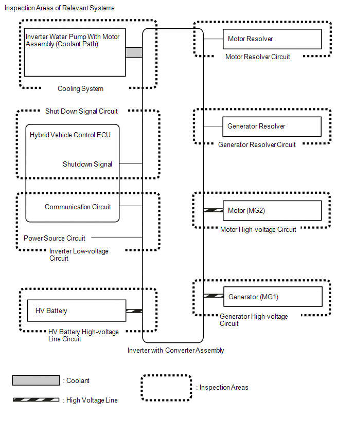 Inspection Details of Relevant Systems
  Inspection Details of Relevant Systems