Toyota Avalon (XX50) 2019-2022 Service & Repair Manual: DC/DC Converter Status Circuit Short to Battery (P0A0812,P0A0814)

Toyota Avalon (XX50) 2019-2022 Service & Repair Manual / Engine / Hybrid / Battery Control / Motor Generator Control System / DC/DC Converter Status Circuit Short to Battery (P0A0812,P0A0814)

DESCRIPTION

The DC/DC converter varies output voltage based on voltage change signals (VLO signal line) received from the motor generator control ECU.

If the vehicle is being driven with an inoperative DC/DC converter, the voltage of the auxiliary battery will drop, which will prevent the continued operation of the vehicle. Therefore, the motor generator control ECU monitors the operation of the DC/DC converter and alerts the driver if it detects a malfunction.

DTC No.

Detection Item

DTC Detection Condition

Trouble Area

MIL

Warning Indicate

P0A0812

DC/DC Converter Status Circuit Short to Battery

Short to +B detected in DC/DC converter VLO signal line

(1 trip detection logic)

  • Wire harness or connector
  • Inverter with converter assembly

Does not come on

Master Warning Light:

Comes on

P0A0814

DC/DC Converter Status Circuit Short to Ground or Open

Open or short to ground detected in DC/DC converter VLO signal line

(1 trip detection logic)

  • Wire harness or connector
  • Inverter with converter assembly

Does not come on

Master Warning Light:

Comes on

CONFIRMATION DRIVING PATTERN

HINT:

After repair has been completed, clear the DTC and then check that the vehicle has returned to normal by performing the following All Readiness check procedure.

Click here

  1. Connect the Techstream to the DLC3.
  2. Turn the power switch on (IG) and turn the Techstream on.
  3. Clear the DTCs (even if no DTCs are stored, perform the clear DTC procedure).
  4. Turn the power switch off and wait for 2 minutes or more.
  5. Turn the power switch on (IG) and turn the Techstream on.
  6. With power switch on (IG) and wait for 10 seconds or more.
  7. Enter the following menus: Powertrain / Motor Generator / Utility / All Readiness.
  8. Check the DTC judgment result.

    HINT:

    • If the judgment result shows NORMAL, the system is normal.
    • If the judgment result shows ABNORMAL, the system has a malfunction.
    • If the judgment result shows INCOMPLETE or N/A, perform driving pattern again.

WIRING DIAGRAM

Refer to the wiring diagram for the DTC P0A1112.

Click here

CAUTION / NOTICE / HINT

CAUTION:

  • Before the following operations are conducted, take precautions to prevent electric shock by turning the power switch off, wearing insulated gloves, and removing the service plug grip from HV battery.
    • Inspecting the high-voltage system
    • Disconnecting the low voltage connector of the inverter with converter assembly
    • Disconnecting the low voltage connector of the HV battery
  • To prevent electric shock, make sure to remove the service plug grip to cut off the high voltage circuit before servicing the vehicle.
  • After removing the service plug grip from the HV battery, put it in your pocket to prevent other technicians from accidentally reconnecting it while you are working on the high-voltage system.
  • After removing the service plug grip, wait for at least 10 minutes before touching any of the high-voltage connectors or terminals. After waiting for 10 minutes, check the voltage at the terminals in the inspection point in the inverter with converter assembly. The voltage should be 0 V before beginning work.

    Click here

    HINT:

    Waiting for at least 10 minutes is required to discharge the high-voltage capacitor inside the inverter with converter assembly.

    *a

    Without waiting for 10 minutes

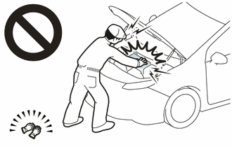
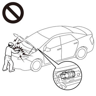
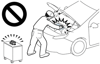
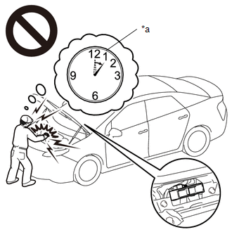
NOTICE:

After turning the power switch off, waiting time may be required before disconnecting the cable from the negative (-) auxiliary battery terminal. Therefore, make sure to read the disconnecting the cable from the negative (-) auxiliary battery terminal notices before proceeding with work.

Click here

PROCEDURE

1.

CHECK CONNECTOR CONNECTION CONDITION (INVERTER WITH CONVERTER ASSEMBLY CONNECTOR)

Click here

Result

Proceed to

OK

A

NG (The connector is not connected securely.)

B

NG (The terminals are not making secure contact or are deformed, or water or foreign matter exists in the connector.)

C

B

CONNECT SECURELY

C

REPAIR OR REPLACE HARNESS OR CONNECTOR

A

2.

CHECK HARNESS AND CONNECTOR (INVERTER WITH CONVERTER ASSEMBLY - IGCT RELAY)

CAUTION:

Be sure to wear insulated gloves.

(a) Check that the service plug grip is not installed.

NOTICE:

After removing the service plug grip, do not turn the power switch on (READY), unless instructed by the repair manual because this may cause a malfunction.

(b) Disconnect the A42 inverter with converter assembly connector.

(c) Remove the IGCT relay from the instrument panel relay block.

(d) Measure the resistance according to the value(s) in the table below.

*1

Instrument Panel Relay Block

*2

IGCT Relay

*a

Front view of wire harness connector

(to Inverter with Converter Assembly)

-

-

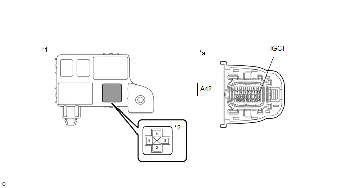
Standard Resistance:

Tester Connection

Condition

Specified Condition

A42-12 (IGCT) - 5 (IGCT relay)

Power switch off

Below 1 Ω

(e) Install the IGCT relay.

(f) Reconnect the A42 inverter with converter assembly connector.

OK

REPLACE INVERTER WITH CONVERTER ASSEMBLY

NG

REPAIR OR REPLACE HARNESS OR CONNECTOR

    Drive Motor "A" Inverter Stuck On (P0A789E,P1C5D19)

    DC/DC Converter Stuck On (P0A949E,P0D3319)

    See More:

    Toyota Avalon (XX50) 2019-2022 Service & Repair Manual > Seat Belt: Child Restraint Seat Anchor Bracket
    ComponentsCOMPONENTS ILLUSTRATION *A for Gasoline Model *B for HV Model *1 CHILD RESTRAINT SEAT ANCHOR BRACKET SUB-ASSEMBLY LH *2 CHILD RESTRAINT SEAT ANCHOR BRACKET SUB-ASSEMBLY RH *3 REAR CENTER SEAT OUTER BELT ASSEMBLY *4 REAR SEAT CUSHION ASSEMBLY *5 REAR SEAT CUSHION LOCK HOOK - - Tightening t ...

    Toyota Avalon (XX50) 2019-2022 Owners Manual

    Toyota Avalon (XX50) 2019-2022 Service & Repair Manual

    © 2024 Copyright www.tavalon.net
    0.0161