PROCEDURE
|
1. | CHECK GENERATOR PULLEY WITH CLUTCH (ON-VEHICLE INSPECTION) |
(a) Start the engine and visually check that the generator rotor assembly (fan) in the generator assembly is operating.
OK:
The generator rotor assembly (fan) is operating.
| NG |  | REPLACE GENERATOR PULLEY WITH CLUTCH |
|
| 2. |
CHECK GENERATOR PULLEY WITH CLUTCH (UNIT INSPECTION) |
(a) Remove the generator assembly.
Click here

(b) Check the installation condition of the generator pulley cap.
OK:
The generator pulley cap is not loose or missing.
(c) Check for forming of particles due to friction (for dry type pulley) or grease leaks (for wet type pulley).
OK:
There are no large amounts of particles (for dry type pulley) or grease leaks (for wet type pulley).
(d) Check the generator pulley with clutch for misalignment (interference with the generator assembly).
OK:
The generator pulley with clutch is not misaligned (no interference with the generator assembly).
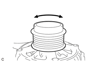
| (e) Turn the generator pulley with clutch clockwise and counterclockwise by hand and check for noise. OK: Noise does not occur when turned in either direction. |
|
(f) Turn the generator pulley with clutch clockwise and counterclockwise by hand and visually check for runout.
OK:
The generator pulley with clutch does not have runout.
(g) Inspect generator pulley with clutch.
Click here
| OK | | REPAIR OR REPLACE GENERATOR ASSEMBLY |
| NG | | REPLACE GENERATOR PULLEY WITH CLUTCH |
DATA LIST / ACTIVE TEST
DATA LIST
HINT:
Using the Techstream to read the Data List allows the values or states of switches, sensors, actuators and other items to be read without removing any parts. This non-intrusive inspection can be very useful because intermittent conditions or signals may be discovered before parts or wiring is disturbed. Reading the Data List information early in troubleshooting is one way to save diagnostic time.
NOTICE:
In the table below, the values listed under Normal Condition are reference values. Do not depend solely on these reference values when deciding whether a part is faulty or not.
(a) Warm up the engine.
(b) Turn the A/C switch off.
(c) Turn the engine switch off.
(d) Connect the Techstream to the DLC3.
(e) Turn the engine switch on (IG).
(f) Turn the Techstream on.
(g) Enter the following menus: Powertrain / Engine / Data List.
(h) According to the display on the Techstream, read the Data List.
HINT:
Normal Condition: If no idling conditions are specified, the shift lever should be in N or P, and the A/C switch and all accessory switches should be off.
Powertrain > Engine > Data List|
Tester Display | Measurement Item |
Range | Normal Condition |
Diagnostic Note |
|---|---|---|---|---|
|
Battery Voltage | Battery voltage |
Min.: 0.0 V Max.: 65.5 V |
11 to 14 V: Idling | If the result is not as specified, abnormal battery voltage is suspected. |
|
Alternator Output Duty Ratio |
Generator output duty | Min.: 0.0% Max.: 399.9% | Changes according to alternator output. |
If the result is not as specified, a malfunction of the charging system is suspected. |
|
Alternator Voltage - Non Active Test |
Requested voltage when regulator forced drive is not executed |
Min.: 0.000 V Max.: 79.998 V |
After engine start: 13.5 to 14.4 V (varies with generator temperature) |
If the result is not as specified, a malfunction of the charging system is suspected. |
|
Voltage of Alternator | Requested voltage when regulator under forced activation |
Min.: 0.0 V Max.: 79.9 V |
After engine start: Approximately same as requested output voltage when Active Test "Control the Voltage of Alternator" is performed |
If the result is not as specified, a malfunction of the charging system is suspected. |
ACTIVE TEST
HINT:
Using the Techstream to perform Active Tests allows relays, VSVs, actuators and other items to be operated without removing any parts. This non-intrusive functional inspection can be very useful because intermittent operation may be discovered before parts or wiring is disturbed. Performing Active Tests early in troubleshooting is one way to save diagnostic time. Data List information can be displayed while performing Active Tests.
(a) Connect the Techstream to the DLC3.
(b) Turn the engine switch on (IG).
(c) Turn the Techstream on.
(d) Enter the following menus: Powertrain / Engine / Active Test.
(e) According to the display on the Techstream, perform the Active Test.
Powertrain > Engine > Active Test|
Tester Display | Measurement Item |
Control Range | Diagnostic Note |
|---|---|---|---|
|
Control the Voltage of Alternator |
Requested output voltage of generator regulator during forced activation |
Between 12.5 and 14.7 V |
Test is possible after engine start |
DIAGNOSIS SYSTEM
DLC3 (Data Link Connector 3)
(a) Check the DLC3.
Click here 
BATTERY VOLTAGE
Standard Voltage:
11 to 14 V
If the voltage is below 11 V, replace or recharge the battery.
DIAGNOSTIC TROUBLE CODE CHART
Charging System|
DTC No. | Detection Item |
Warning Indicate | Memory |
Note | Link |
|---|---|---|---|---|---|
|
P161A87 | Lost Communication with Alternator Missing Message |
Charge warning is not displayed |
DTC stored | SAE Code: P161A |
|
DTC CHECK / CLEAR
CHECK DTC
(a) Connect the Techstream to the DLC3.
(b) Turn the engine switch on (IG).
(c) Turn the Techstream on.
(d) Enter the following menus: Powertrain / Engine / Trouble Codes.
Powertrain > Engine > Trouble Codes(e) Check the details of the DTCs.
Click here

CLEAR DTC
(a) Connect the Techstream to the DLC3.
(b) Turn the engine switch on (IG).
(c) Turn the Techstream on.
(d) Enter the following menus: Powertrain / Engine / Trouble Codes.
(e) Clear the DTCs.
Powertrain > Engine > Clear DTCsFAIL-SAFE CHART
If the following DTC is stored, the ECM enters fail-safe mode to allow the vehicle to be driven temporarily.
|
DTC No. | Fail-safe Operation |
Fail-safe Deactivation Condition |
|---|---|---|
|
P161A87 | Generator command is fixed. |
Engine switch is turned on (IG) after condition returns to normal. |
FREEZE FRAME DATA
DESCRIPTION
The ECM records vehicle and driving condition information as freeze frame data the moment a DTC is stored. When troubleshooting, freeze frame data can be helpful in determining whether the vehicle was moving or stationary, whether the engine was warmed up or not, whether the air fuel ratio was lean or rich, as well as other data recorded at the time of a malfunction.
HINT:
LIST OF FREEZE FRAME DATA
Powertrain > Engine|
Tester Display |
|---|
| Battery Voltage |
|
Alternator Output Duty Ratio |
|
Alternator Voltage - Non Active Test |
|
Voltage of Alternator |
CAUTION / NOTICE / HINT
HINT:
*: Use the Techstream.
PROCEDURE
| 1. |
VEHICLE BROUGHT TO WORKSHOP |
|
| 2. |
CUSTOMER PROBLEM ANALYSIS |
HINT:
|
What |
Vehicle model, system name |
|
When |
Date, time, occurrence frequency |
|
Where |
Road conditions |
|
Under what conditions? |
Running conditions, driving conditions, weather conditions |
|
How did it happen? |
Problem symptoms |
|
| 3. |
INSPECT BATTERY VOLTAGE |
(a) Measure the battery voltage.
Standard Voltage:
11 to 14 V
If the voltage is below 11 V, recharge or replace the battery before proceeding to the next step.
|
| 4. |
INSPECT COMMUNICATION FUNCTION OF CAN COMMUNICATION SYSTEM* |
(a) Check if CAN communication DTCs are output.
Click here

|
Result | Proceed to |
|---|---|
|
CAN communication DTCs are not output. |
A |
| CAN communication DTCs are output. |
B |
| B |
 | GO TO CAN COMMUNICATION SYSTEM |
|
| 5. |
CHECK FOR DTC* |
HINT:
Refer to DTC Check / Clear.
Click here
| Result |
Proceed to |
|---|---|
| DTCs are not output. |
A |
| DTCs are output. |
B |
| B |
| GO TO DTC CHART |
|
| 6. |
REFER TO PROBLEM SYMPTOMS TABLE |
HINT:
Refer to Problem Symptoms Table.
Click here
|
Result | Proceed to |
|---|---|
|
Malfunctioning parts are not confirmed. |
A |
| Malfunctioning parts are confirmed. |
B |
| B |
| GO TO STEP 12 |
|
| 7. |
OVERALL ANALYSIS AND TROUBLESHOOTING* |
HINT:
Refer to Data List / Active Test.
Click here
|
Result | Proceed to |
|---|---|
|
Malfunctioning parts are not confirmed. |
A |
| Malfunctioning parts are confirmed. |
B |
| B |
| GO TO STEP 12 |
|
| 8. |
CHECK ECM CIRCUIT |
HINT:
Refer to Terminals of ECM.
Click here
| NG | | GO TO STEP 12 |
|
| 9. |
CHECK FOR INTERMITTENT PROBLEMS |
HINT:
Refer to Symptom Simulation.
Click here
|
| 10. |
CONDUCT PARTS INSPECTION |
|
| 11. |
IDENTIFY PROBLEM |
|
| 12. |
ADJUST AND/OR REPAIR |
|
| 13. |
CONDUCT CONFIRMATION TEST |
| NEXT | | END |
PROCEDURE
|
1. | CONFIRM PROBLEM SYMPTOM |
(a) Confirm the problem symptom.
|
Symptom | Proceed to |
|---|---|
|
Noise occurs from V-ribbed belt. |
A |
| Noise occurs from generator assembly. |
B |
| B |
 | GO TO STEP 6 |
|
| 2. |
CHECK V-RIBBED BELT FOR WEAR |
(a) Check the V-ribbed belt for wear or damage.
OK:
The V-ribbed belt is not worn or damaged.
| NG | | REPLACE V-RIBBED BELT |
|
| 3. |
CHECK GENERATOR PULLEY WITH CLUTCH FOR WEAR |
(a) Check the grooves of the generator pulley with clutch for wear or damage.
OK:
The grooves of the generator pulley with clutch are not worn or damaged.
| NG | | REPLACE GENERATOR PULLEY WITH CLUTCH |
|
| 4. |
CHECK FOR NOISE WHILE CLUTCH PULLEY IS OPERATING |
(a) Start the engine and check the generator pulley with clutch for looseness.
OK:
The generator pulley with clutch is not loose.
| NG | | TIGHTEN GENERATOR PULLEY WITH CLUTCH TO SPECIFIED TORQUE |
|
| 5. |
INSPECT GENERATOR PULLEY WITH CLUTCH (UNIT INSPECTION) |
(a) Remove the generator assembly.
Click here

(b) Check the installation condition of the generator pulley cap.
OK:
The generator pulley cap is not loose or missing.
(c) Check for forming of particles due to friction (for dry type pulley) or grease leaks (for wet type pulley).
OK:
There are no large amounts of particles (for dry type pulley) or grease leaks (for wet type pulley).
(d) Check the generator pulley with clutch for misalignment (interference with the generator assembly).
OK:
The generator pulley with clutch is not misaligned (no interference with the generator assembly).
| (e) Turn the generator pulley with clutch clockwise and counterclockwise by hand and check for noise. OK: Noise does not occur when turned in either direction. |
|
(f) Turn the generator pulley with clutch clockwise and counterclockwise by hand and visually check for runout.
OK:
The generator pulley with clutch does not have runout.
(g) Inspect generator pulley with clutch.
Click here
| OK | | INSPECT PULLEY OTHER THAN GENERATOR ASSEMBLY PULLEY |
| NG | | REPLACE GENERATOR PULLEY WITH CLUTCH |
| 6. |
CHECK FOR NOISE WHEN ROTOR IS TURNING FREELY |
(a) Perform a road test and check that noise does not occur when decelerating.
OK:
Noise does not occur.
(b) Stop the engine and check that generator pulley with clutch noise does not occur as the engine stops.
OK:
Noise does not occur.
| NG | |
REPLACE GENERATOR PULLEY WITH CLUTCH |
|
| 7. |
CHECK GENERATOR W/CLUTCH PULLEY |
(a) Inspect generator pulley with clutch.
Click here
| OK | | REPAIR OR REPLACE GENERATOR ASSEMBLY |
| NG | | REPLACE GENERATOR PULLEY WITH CLUTCH |
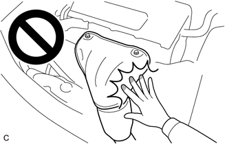
ON-VEHICLE INSPECTION
CAUTION / NOTICE / HINT
CAUTION:
PROCEDURE
1. CHECK BATTERY CONDITION
NOTICE:
If the battery is weak or if the engine is difficult to start, recharge the battery and perform inspections again before returning the vehicle to the customer.
(a) Check the battery for damage or deformation. If severe damage, deformation or leakage is found, replace the battery.
(b) Check the electrolyte level in each cell.
(1) For maintenance-free batteries:
HINT:
Before checking the battery voltage, turn off all the electrical systems (headlights, blower motor, rear window defogger, etc.).
| (2) For non-maintenance-free batteries:
|
|
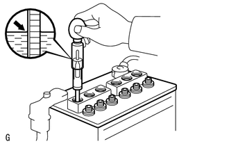
(c) Check the voltage.
(1) Turn the engine switch off and turn on the headlights for 20 to 30 seconds. This will remove the surface charge from the battery.
(2) Measure the battery voltage according to the value(s) in the table below.
Standard Voltage:
|
Tester Connection | Condition |
Specified Condition |
|---|---|---|
|
Positive (+) terminal - Negative (-) terminal |
20°C (68°F) | 12.3 V or higher |
If the voltage is not as specified, recharge or replace the battery.
2. INSPECT BATTERY TERMINAL AND FUSE
(a) Check that the battery terminals are not loose or corroded.
If the terminal is corroded, clean the terminal.
Torque:
Positive (+) Battery Terminal :
5.4 N·m {55 kgf·cm, 48 in·lbf}
Negative (-) Battery Terminal :
5.4 N·m {55 kgf·cm, 48 in·lbf}
(b) Measure the resistance of the fuses.
Standard Resistance:
Below 1 Ω
If the result is not as specified, replace the fuse.
3. INSPECT V-RIBBED BELT
Click here 
4. INSPECT GENERATOR WIRING
(a) Visually check the generator wiring.
(1) Check that the wiring is in good condition.
5. CHECK FOR ABNORMAL NOISE
(a) Check for abnormal noises from the generator assembly.
(1) Check that no abnormal noises are heard from the generator assembly while the engine is running.
If noise occurs, refer to Problem Symptoms Table.
Click here
6. INSPECT CHARGING CIRCUIT WITHOUT LOAD
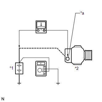
CAUTION:
| (a) Connect a voltmeter and an ammeter to the charging circuit as follows. HINT: If a battery/generator assembly tester is available, connect the tester to the charging circuit in accordance with the manufacturer's instructions. (1) Disconnect the wire from terminal B of the generator assembly and connect it to the negative (-) lead of the ammeter. (2) Connect the ammeter positive (+) lead to terminal B of the generator assembly. (3) Connect the voltmeter positive (+) lead to the positive (+) terminal of the battery. (4) Ground the voltmeter negative (-) lead. |
|
(b) Check the charging circuit.
(1) Maintain the engine speed at 2000 rpm and check the readings on the ammeter and voltmeter.
Standard Current:
10 A or more
Standard Voltage:
13.5 to 14.4 V
If the result is not as specified, repair or replace the generator assembly.
7. INSPECT CHARGING CIRCUIT WITH LOAD
CAUTION:
(a) With the engine running at 2000 rpm, turn the high beam headlights on and turn the heater blower switch to the "HI" position.
(b) Check the reading on the ammeter.
Standard Current:
30 A or more
If the result is not as specified, repair or replace the generator assembly.
HINT:
If the battery is fully charged, the reading will sometimes be less than the standard. If this is the case, add more electrical load (operate the wipers, rear window defogger, etc.) and check the reading on the ammeter again.
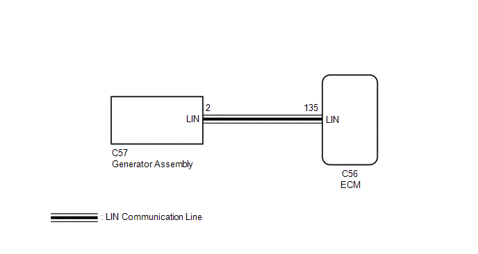
DESCRIPTION
The ECM communicates with the generator assembly via LIN communication. If a LIN communication error is detected, the ECM stores this DTC.
|
DTC No. | Detection Item |
DTC Detection Condition | Trouble Area |
Warning Indicate | Memory |
Note |
|---|---|---|---|---|---|---|
| P161A87 |
Lost Communication with Alternator Missing Message |
Generator assembly or ECM communication stops for approximately 17 minutes or more with the engine switch on (IG). (1 trip detection logic) |
| Charge warning is not displayed |
DTC stored | SAE Code: P161A |
WIRING DIAGRAM
PROCEDURE
| 1. |
CHECK CHARGING SYSTEM |
(a) Check the charging system.
Click here 
| NG |  | REPAIR OR REPLACE CHARGING SYSTEM |
|
| 2. |
CHECK HARNESS AND CONNECTOR (ECM - GENERATOR ASSEMBLY) |
(a) Disconnect the C56 ECM connector.
(b) Disconnect the C57 generator assembly connector.
(c) Measure the resistance according to the value(s) in the table below.
Standard Resistance:
|
Tester Connection | Condition |
Specified Condition |
|---|---|---|
|
C56-135 (LIN) - C57-2 (LIN) |
Always | Below 1 Ω |
|
C56-135 (LIN) or C57-2 (LIN) - Body ground |
Always | 10 kΩ or higher |
| OK | | REPLACE GENERATOR ASSEMBLY |
| NG | | REPAIR OR REPLACE HARNESS OR CONNECTOR |
PARTS LOCATION
ILLUSTRATION
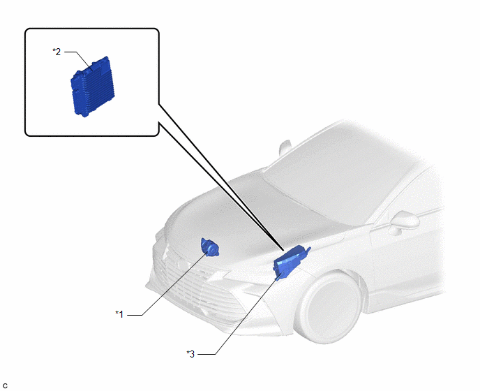
|
*1 | GENERATOR ASSEMBLY |
*2 | ECM |
|
*3 | ENGINE ROOM RELAY BLOCK AND JUNCTION BLOCK ASSEMBLY |
- | - |
ILLUSTRATION
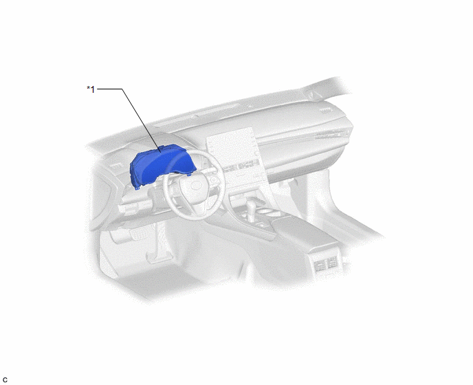
|
*1 | COMBINATION METER ASSEMBLY |
- | - |
PRECAUTION
INITIALIZATION
NOTICE:
Click here 
CHARGING SYSTEM PRECAUTION
NOTICE:
PROBLEM SYMPTOMS TABLE
HINT:
|
Symptom | Suspected Area |
Link |
|---|---|---|
|
Charge warning is displayed |
Battery |
|
|
Generator assembly |
| |
|
Charging system |
| |
|
Charging failure | Generator pulley with clutch |
|
|
Generator assembly | ||
|
Noise occurs from V-ribbed belt or generator assembly |
V-ribbed belt |
|
|
Generator pulley with clutch | ||
|
Generator assembly |
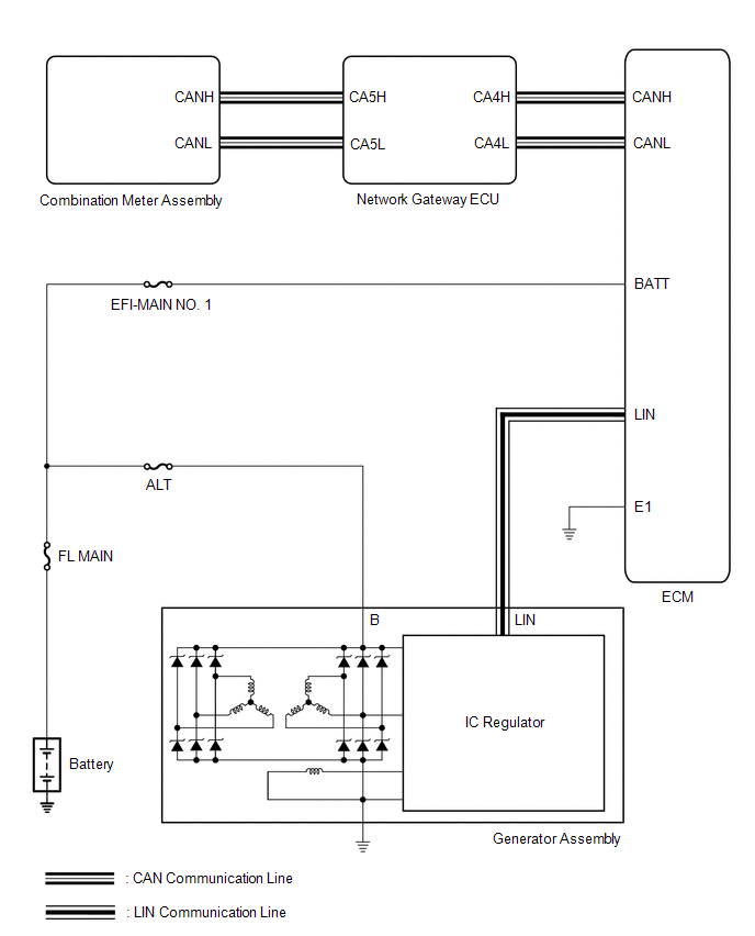
SYSTEM DIAGRAM
TERMINALS OF ECM

HINT:
The standard normal voltage and resistance between each pair of ECM terminals is shown in the table below. The appropriate conditions for checking each pair of terminals are also indicated. The result of checks should be compared with the standard normal voltage and resistance for that pair of terminals, displayed in the Specified Condition column. The illustration above can be used as a reference to identify the ECM terminal locations.
|
Terminal No. (Symbol) | Wiring Color |
Terminal Description | Condition |
Specified Condition |
|---|---|---|---|---|
|
C56-53 (E1) - Body ground |
W-B - Body ground | Ground |
Always | Below 1 Ω |
|
A18-1 (BATT) - C56-53 (E1) |
R - W-B | Battery (for measuring battery voltage and for ECM memory) |
Always | 11 to 14 V |
|
C56-135 (LIN) - Body ground |
B - Body ground | LIN communication line |
Engine switch off (while LIN communication stopped) |
10 kΩ or higher |
Toyota Avalon (XX50) 2019-2022 Service & Repair Manual > Navigation System(for Gasoline Model): Panel Switches do not Function. Parking Brake Switch Circuit. Parts Location
Panel Switches do not Function CAUTION / NOTICE / HINT NOTICE: Depending on the parts that are replaced during vehicle inspection or maintenance, performing initialization, registration or calibration may be needed. Refer to Precaution for Navigation System. Click here When replacing the radio and d ...