DESCRIPTION
|
Detection Item | Symptom |
Trouble Area |
|---|---|---|
| Blind Spot Monitor Sensor Communication Stop Mode |
Any of the following conditions are met:
|
|
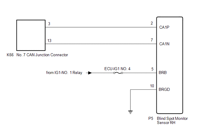
WIRING DIAGRAM
CAUTION / NOTICE / HINT
CAUTION:
When performing the confirmation driving pattern, obey all speed limits and traffic laws.
NOTICE:
Click here 
Click here
DTC check procedure: Turn the engine switch on (IG) and wait for 1 minute or more. Then operate the suspected malfunctioning system and drive the vehicle at 60 km/h (37 mph) or more for 5 minutes or more.
Click here
HINT:
PROCEDURE
|
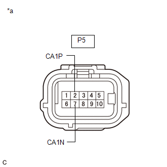
1. | CHECK FOR OPEN IN CAN BUS LINES (BLIND SPOT MONITOR SENSOR RH BRANCH LINE) |
(a) Disconnect the cable from the negative (-) battery terminal.
(b) Disconnect the P5 blind spot monitor sensor RH connector.
| (c) Measure the resistance according to the value(s) in the table below. Standard Resistance:
|
|
| NG |  | REPAIR OR REPLACE CAN BRANCH LINES OR CONNECTOR (BLIND SPOT MONITOR SENSOR RH) |
|
| 2. |
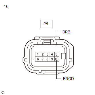
CHECK HARNESS AND CONNECTOR (POWER SOURCE CIRCUIT) |
| (a) Measure the resistance according to the value(s) in the table below. Standard Resistance:
|
|
(b) Reconnect the cable to the negative (-) battery terminal.
(c) Measure the voltage according to the value(s) in the table below.
Standard Voltage:
|
Tester Connection | Condition |
Specified Condition |
|---|---|---|
|
P5-5 (BRB) - Body ground |
Engine switch on (IG) |
11 to 14 V |
| OK | | REPLACE BLIND SPOT MONITOR SENSOR RH |
| NG | | REPAIR OR REPLACE HARNESS OR CONNECTOR (POWER SOURCE CIRCUIT) |
DESCRIPTION
|
Detection Item | Symptom |
Trouble Area |
|---|---|---|
| Center Airbag Sensor Communication Stop Mode |
Any of the following conditions are met:
|
|
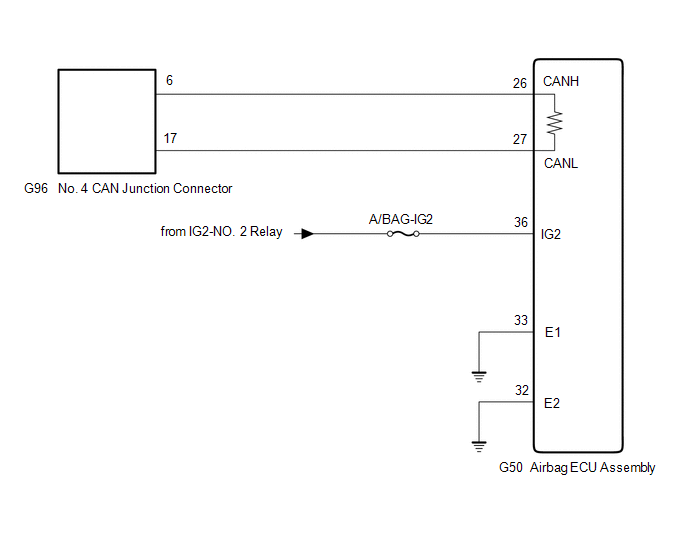
WIRING DIAGRAM
CAUTION / NOTICE / HINT
CAUTION:
When performing the confirmation driving pattern, obey all speed limits and traffic laws.
NOTICE:
Click here 
Click here
DTC check procedure: Turn the engine switch on (IG) and wait for 1 minute or more. Then operate the suspected malfunctioning system and drive the vehicle at 60 km/h (37 mph) or more for 5 minutes or more.
Click here
HINT:
PROCEDURE
|
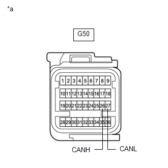
1. | CHECK FOR OPEN IN CAN BUS LINES (AIRBAG ECU ASSEMBLY MAIN LINE) |
(a) Disconnect the cable from the negative (-) battery terminal.
(b) Disconnect the G50 airbag ECU assembly connector.
| (c) Measure the resistance according to the value(s) in the table below. Standard Resistance:
|
|
| NG |  | REPAIR OR REPLACE CAN MAIN BUS LINES OR CONNECTOR (AIRBAG ECU ASSEMBLY) |
|
| 2. |
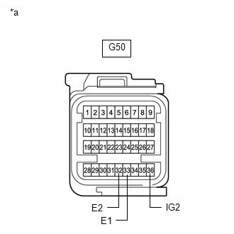
CHECK HARNESS AND CONNECTOR (POWER SOURCE CIRCUIT) |
| (a) Measure the resistance according to the value(s) in the table below. Standard Resistance:
|
|
(b) Reconnect the cable to the negative (-) battery terminal.
(c) Measure the voltage according to the value(s) in the table below.
Standard Voltage:
|
Tester Connection | Condition |
Specified Condition |
|---|---|---|
|
G50-36 (IG2) - Body ground |
Engine switch on (IG) |
11 to 14 V |
| OK | | REPLACE AIRBAG ECU ASSEMBLY |
| NG | | REPAIR OR REPLACE HARNESS OR CONNECTOR (POWER SOURCE CIRCUIT) |
DESCRIPTION
|
Detection Item | Symptom |
Trouble Area |
|---|---|---|
| Certification ECU Communication Stop Mode |
Any of the following conditions are met:
|
|
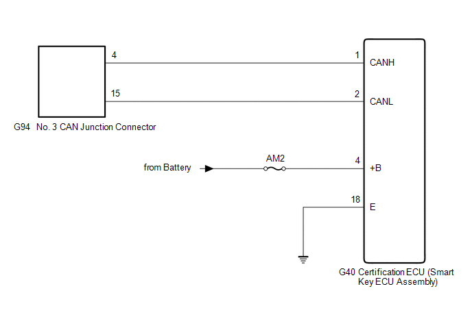
WIRING DIAGRAM
CAUTION / NOTICE / HINT
CAUTION:
When performing the confirmation driving pattern, obey all speed limits and traffic laws.
NOTICE:
Click here 
Click here
DTC check procedure: Turn the engine switch on (IG) and wait for 1 minute or more. Then operate the suspected malfunctioning system and drive the vehicle at 60 km/h (37 mph) or more for 5 minutes or more.
Click here
Click here
HINT:
PROCEDURE
|
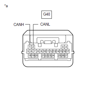
1. | CHECK FOR OPEN IN CAN BUS LINES (CERTIFICATION ECU (SMART KEY ECU ASSEMBLY) BRANCH LINE) |
(a) Disconnect the cable from the negative (-) battery terminal.
(b) Disconnect the G40 certification ECU (smart key ECU assembly) connector.
| (c) Measure the resistance according to the value(s) in the table below. Standard Resistance:
|
|
| NG |  | REPAIR OR REPLACE CAN BRANCH LINES OR CONNECTOR (CERTIFICATION ECU (SMART KEY ECU ASSEMBLY)) |
|
| 2. |
CHECK HARNESS AND CONNECTOR (POWER SOURCE CIRCUIT) |
| (a) Measure the resistance according to the value(s) in the table below. Standard Resistance:
|
|
(b) Reconnect the cable to the negative (-) battery terminal.
(c) Measure the voltage according to the value(s) in the table below.
Standard Voltage:
|
Tester Connection | Condition |
Specified Condition |
|---|---|---|
|
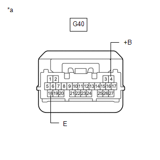
G40-4 (+B) - Body ground |
Always | 11 to 14 V |
| OK | | REPLACE CERTIFICATION ECU (SMART KEY ECU ASSEMBLY) |
| NG | | REPAIR OR REPLACE HARNESS OR CONNECTOR (POWER SOURCE CIRCUIT) |
Toyota Avalon (XX50) 2019-2022 Service & Repair Manual > Sfi System: Fuel Rail / System Pressure - Too High (P008800). Mass or Volume Air Flow Sensor "A" Circuit Short to Battery (P010012,P010014). Mass or Volume Air Flow Sensor "A" Signal Plausibility Failure (P010064
Fuel Rail / System Pressure - Too High (P008800) DESCRIPTION Refer to DTC P008700. Click here DTC No. Detection Item DTC Detection Condition Trouble Area MIL Memory Note P008800 Fuel Rail / System Pressure - Too High Although the ECM is requesting the fuel pump assembly (for high pressure side) to o ...